GRINDING MILLS
Most of the tonnage milled today is ground in one of the following types of equipment or a combination of two or more: ball mills, tube mills, rod mills, and stamps. Chilean mills and Huntington mills are used only in a few isolated cases today.
BALL AND TUBE MILLS
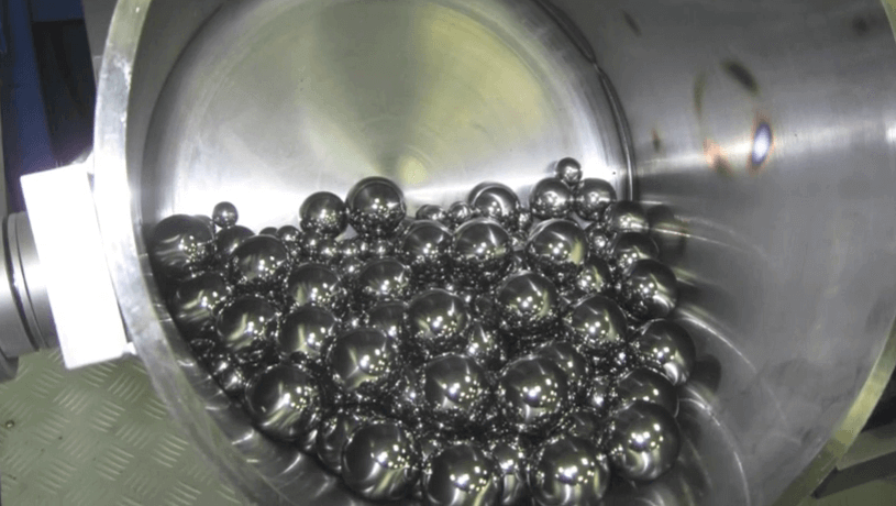
All types of Ore Grinding Mills that consist essentially of rotating cylinders with flat or conical ends with balls, pebbles, or rods used as grinding media are included here.
BALL MILLS
The term “ball mill’ is generally used to refer to a cylindrical mill whose length is less than, equal to, but not much greater than its diameter. It was initially developed for relatively coarse grinding, but by using it in closed circuit with a classifier its use has been extended for fine grinding.
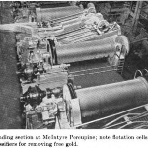
Ball mills have shells of cast iron or steel plates and are carried on hollow trunnions. Ore is fed through a scoop, drum-type, or combination feeder at one end and is discharged from the opposite trunnion.
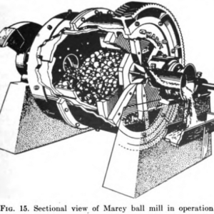
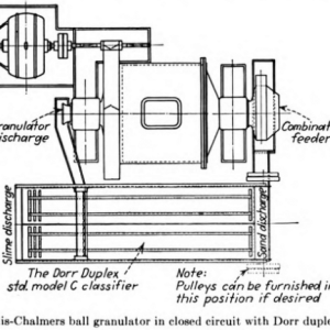
Ball mills may be arbitrarily classified into two types, according to the method of pulp discharge. In high-level or overflow mills the pulp level builds up until it overflows and discharges through the trunnion. High- level discharge mills are made by a large number of manufacturers throughout the world. Low-level mills are typified by the Allis-Chalmers and Marcy (see Figs. 14 and 15) grate-discharge mills. The discharge end is fitted with grates; between the grates and the end of the mill are radial lifters which act as a pump to lift the discharge to the hollow trunnion. Drive is by spur or herringbone gear, direct connected or belt driven.
Ball mills are built in sizes ranging from small laboratory mills to a present maximum of 12 ft. diameter by 12 ft. long, the latter requiring close to 1000 hp. Liners are usually of manganese steel, of chrome steel, or white iron, 3 to 6 in. thick. Corrugated and shiplap construction is commonly used to increase the grinding action.
CONICAL MILLS
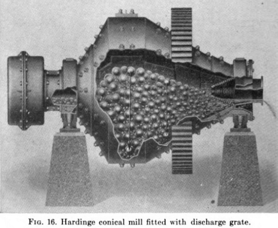
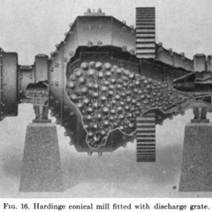
The Hardinge mill (see Fig. 16) differs from most ball mills in that conical ends are added to the cylindrical portion of the mill. The cone at the feed end has a larger open angle than that at the opposite end. Its makers state that the large balls concentrate near the feed end of the mill where the coarsest ore collects and the smaller balls act on the finer ore.
ROD MILLS
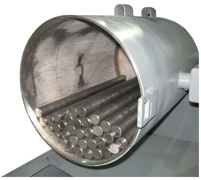
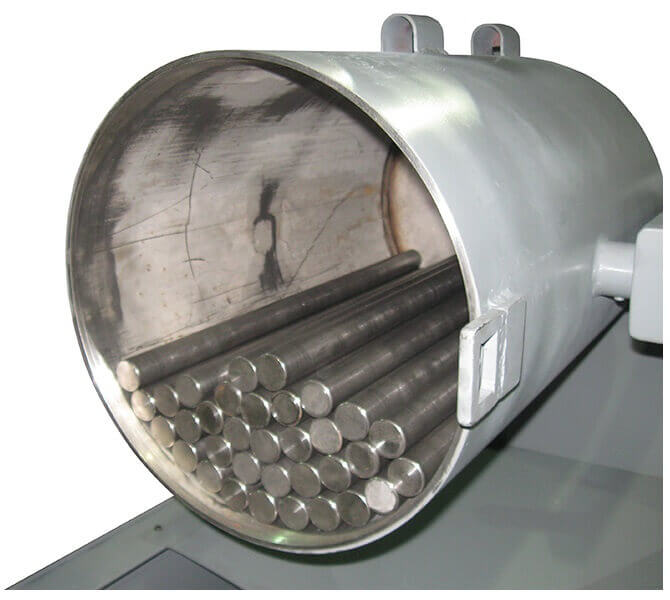
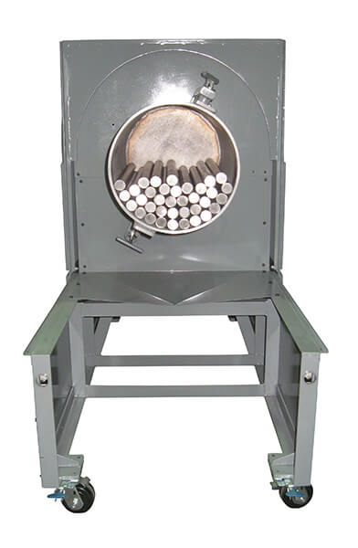
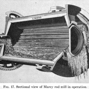
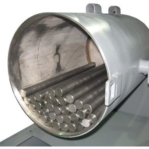
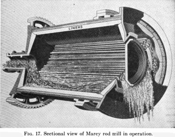
Rod mills (see Fig. 17) follow the general dimensions of tube mills with diameters from 3 to 6 ft. and lengths from two to three times their diameter. They differ from ball mills in that steel rods 3 or 4 in. shorter than the mill length inside the liners are used as grinding media. Rod mills are often run on tires and rollers instead of trunnions or on one trunnion and one tire and set of rollers.
Low-level discharge is obtained on Marcy rod mills by having a beveled annular ring at the discharge end. A stationary steel door fits close to this beveled ring and serves to hold the rods in the mill while pulp discharges between the mill and the door.
TUBE MILLS
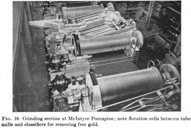
The distinction between tube mills and ball mills is not so marked as their names indicate. Mills from 4 to 6 ft. in diameter and from 16 to 22 ft. long are usually termed tube mills. This was the first type of rotary mill for metallurgical purposes. Because of the necessity of completing the grind during one passage (open circuit) of the ore through the mill, it was built with a large length-diameter ratio. The tube mill is still largely used in South Africa and to some extent in North America for fine grinding generally following some other primary mills.
Tube mills are usually supported on hollow trunnions, the feed entering through a feed scoop at one end and discharging through the other. Drive is by a large gear fitted over the mill shell. Various types of liners are used, as in ball mills.
Flint pebbles and hard waste rock were first used as grinding media, but present practice is to use small steel balls (less than 2 in.) or, as in South Africa, a mixed steel ball and rock load.
GRINDING MILL LINERS
All rotary mills must be fitted with some kind of replaceable liners. Chrome steel, manganese steel, and white iron are generally used. Shapes designed to give a corrugated or shiplap surface to the interior of the mill are often used to prevent slippage of the ball load. Pocket liners are also common. These liners have pockets in which the balls become lodged to form the wearing surface.
Rubber liners have been tried experimentally but have not been adopted by the industry. According to Taggart, no fully satisfactory method of holding the liners in place was worked out, utility was limited to fine feeds and small balls, mill capacity was reduced, and while a slightly higher grinding efficiency was shown in comparative tests with steel liners, there was no indication that possible increased wear for rubber would offset its far greater cost. Silex liners with flint pebbles for grinding media are sometimes used where iron contamination must be avoided.
ORE GRINDING MILL THEORY
BALL AND TUBE MILLS
Grinding Action INSIDE Mill
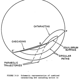
The grinding that takes place in mills of this type is usually ascribed to two actions, impact and attrition, although some authors do not believe that a sharp line of demarcation can be drawn between the two actions.
In rod mills there is line contact between the rods, there is less grinding by impact, and the action resembles that of crushing rolls. As a result, a rod-mill product usually contains a greater percentage near the limiting size with less extreme fines than ball or tube mills.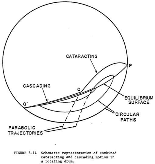
GRINDING MILL CAPACITIES
It is generally accepted that in the case of a given ore the amount of grinding which can be accomplished through a particular mesh by a ball or rod mill is dependent upon two factors:
- The size of the grinding media.
- The net power input to the mill.
In selecting the correct grinding media it is important that the rods or balls supplied be large enough to break the largest particles of ore in the feed, and as already discussed, a seasoned load composed of balls of all sizes, which is the condition found in a mill that has been operating for some time, gives better grinding efficiency than a new charge.
Assuming that the correct grinding media has been established, the net power input can be varied by varying
- The total weight of the grinding media.
- The speed of the mill.
- The size of the discharge opening.
- The percentage solids in the pulp.
The volume of the charge is limited to a maximum of about 50 per cent of the mill volume. If the charge is too large, its center of gravity shifts too near the axis of the mill and the power input falls.
The speed of the mill is limited by what is known as the “critical speed.” This is the speed at which (assuming no slippage) the charge starts to cling to the liners, or to “centrifuge.” It is given by the formula.
N = 76.50/√d
where N = revolutions per minute
d = diameter in feet inside the liners
In practice, the speeds used vary from 60 to 80 per cent of critical, depending upon the individual preference of manufacturers and operators.
The size of the discharge opening governs the amount of pulp held in the mill, and too large a pulp volume reduces the power input for the reason discussed above.
The percentage of solids in the pulp is usually maintained at 60 to 75 per cent, the principle being to keep the volume percentage of solids as high as possible without loss of mobility of the charge. The correct proportion of water present will depend on the kind of ore being handled, slimy ores in general requiring a higher dilution than ores that have a low slime content.
The size of mill required for a specific grinding problem will depend on the character and size of the feed and the product desired and whether open- or closed-circuit grinding is desired. An accurate estimate of capacity can be made only by an engineer familiar with the proper evaluation of the factors involved.
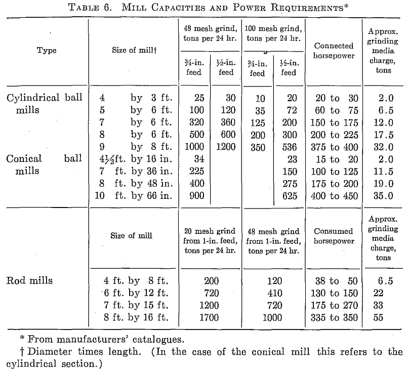
For rough estimating purposes Table 6 gives approximate capacities grinding to 48 and 100 mesh for several size mills. Connected horsepower is also shown. These figures are for what would normally be considered average siliceous ore and for nominal circulating loads of 2 or 3 to 1.
These capacities may be reduced by as much as 50 per cent in the case of a hard, tough ore which is highly resistant to grinding, and for this reason considerable thought has in recent years been given to methods for determining the relative grindability of different ores and to correlating laboratory figures with plant performance. F. C. Bond has published comprehensive grindability data based on work carried out by the Allis-Chalmers Manufacturing Co. and grindability tests are a regular part of the testing procedure of the Dorr Company at the Westport, Conn., laboratories.
OPEN AND CLOSED-CIRCUIT GRINDING
When the tube mill was first introduced, grinding was done in open circuit; i.e., the ore was ground to pass the limiting screen size by one passage through the mill. It was found, however, that if sufficient time of contact between the ore and grinding media were provided to ensure that no unground particles (or oversize) discharged from the mill, an excessive amount of fines were produced. This meant that the ore was ground much finer than necessary and mill capacity was correspondingly reduced.
The difficulty was overcome by placing a classifier in the circuit to separate out oversize from the mill discharge and return it to the mill feed. In closed-circuit grinding no attempt is made to finish the grind in one passage through the mill, but every effort is made to remove finished material as soon as it is released, thus reducing over-grinding and preventing the fines from hindering the grinding action on yet unreduced particles. In this way the tonnage that a given mill will grind is much greater than it is possible to grind in open circuit.
By using wide classifiers with high raking capacity, circulating-load ratios are now being carried to 4:1 or higher. The direct result of the increased capacity is reduced power, liner, and grinding media consumption per ton of finished ore.
There is, of course, a limit as to how large a circulating load can be carried in practice. While capacity continues apparently to improve, though at a decreased rate, it becomes increasingly difficult to move the growing volume of material through the system.
There is some controversy in the literature as to the definition of ratio of circulating load. The term used by most millmen is the ratio of sand tonnage returned to the mill to the tons of original feed.
If the mill-classifier circuit is fed into the classifier instead of into the mill, the sand contains oversize from the original feed as well as oversize from mill discharge, and thus the definition is not entirely accurate.
The ratio of circulating load can be calculated from screen analyses by using the following formulas:
1. When the raw feed enters the mill directly:
Circulating-load ratio = d – o/s – d
where d = cumulative percentage 0n any mesh in the mill discharge
o = cumulative percentage on same mesh in the classifier overflow
s = cumulative percentage on same mesh in the classifier sand
2. When the raw feed enters the classifier:
Circulating-load ratio = f – o/s – d
where f = cumulative percentage on any mesh in the raw feed d, s, o, are the same as in 1
The usual procedure in using these formulas is to calculate the circulating-load ratio for several size screens and discard any that appear out of line, averaging the remainder.
GRINDING FLOWSHEETS
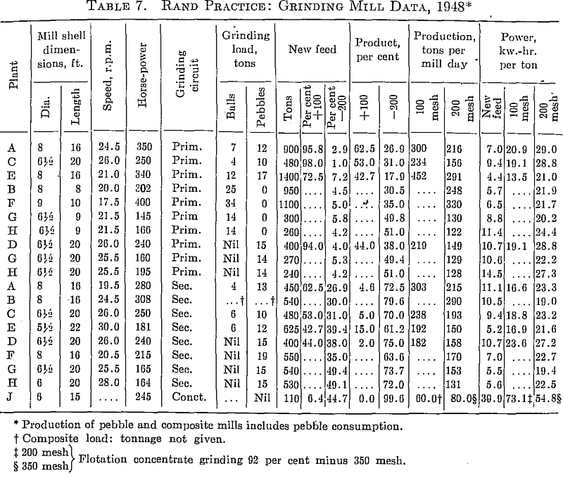
There are many types of flow sheets in use today. The tendency in new mills is to crush relatively fine (¾ to ½ in.). Single-stage ball mills in closed circuit with classifiers are used for grinds coarser than 48 mesh, but when a finer product is desired, two stages of ball mills in closed circuit with classifiers is usual. Efficiency must necessarily be sacrificed to some extent in small mills by capital requirements, and even greater reduction ratios are justified in a single-stage grinding unit.
With the large classifiers used for high circulating loads it is quite often necessary to use some kind of auxiliary device to complete the closed circuit. A large motor-driven scoop lifting the mill discharge to the classifier has been successful.
Rod mills are used to some extent for relatively coarse grinding, and the trend today is to use them in open circuit for the primary grinding stage.
In North America stage grinding is often carried out with ball mills as primary grinders and tube mills for fine grinding in the second stage.
OLD ORE GRINDING MILLS
STAMP MILLS
Although the stamp mill could be classified as a fine crusher, it is included in this chapter, as its usual duty corresponds approximately to that of a primary ball mill.
Stamp mills were built to parallel the operation of a mortar and pestle, working continuously and on a large scale. Ore is fed into a mortar and is crushed by the dropping of the stamp on a die at the bottom of the mortar. The crushed ore discharges through a screen in the side of the mortar.
The shoe that forms the wearing surface on the dropping stamp is attached to a steel stem and is replaceable. The stem is lifted by a cam operating against a tappet which is bolted to the stem. A common camshaft activates usually five stamps in a battery.
The most highly developed mill of this class is called the “California stamp mill,” a complete description of which can be found in Richard and Locke’s Text Book of Ore Dressing ” p. 38, 1940.
Milling was done in unique, crude wooden stamp mills developed by the ingenious Antioquenan miner. Made entirely of hand-hewn hardwrnod (except for cast-iron shoes, several bolts, and a few nails) these molinos Antioquenos have a stamp duty of approximately 0.4 tons per 24 hr. They are powered by overshot water wheels, 18 to 24 ft. in diameter, mounted directly on the 18- to 24-in. wooden camshaft of the mill. Up to 56 drops per minute can be obtained with a water-wheel speed of 14 r.p.m. The stamps, 6½ by 7½ in. by 14 ft. in dimensions, weigh 450 to 500 lb. including the cast-iron shoe. The mills are usually built with three stamps to the mortar box and as many as three sets (nine stamps) per mill. Battery-box screens are usually made of tin from 5-gal. gasoline cans perforated with a small nail. Stamp guides, cams, and the hardwood camshaft bearings are lubricated with beef tallow.
Modern stamp mills employ stamps weighing from 850 to 1500 lb. in the United States and 1500 to 2200 lb. (the Nissen stamp) in South Africa.
Stamps drop at a rate of about 100 per minute and grind about 3 to 5 tons of rock per stamp per 24 hr. Water consumption averages around 6.5 tons per ton of ore.
The stamp mill was originally devised as a combination grinding and amalgamating device before the days of cyanidation. Its use continued with the introduction of the cyanide process, where it was well suited to the comparatively coarse crushing used, the distribution of the ground pulp over amalgamation plates, and the steps of separate cyanidation of sand and slimes that followed. As the “all-sliming” method became more generally adopted, however, with the need for fine grinding in ball mills and preferably in cyanide solution, the stamp mill tended either to be used as a secondary crusher or to be replaced altogether by dry-crushing equipment.
Small stamp-mill installations are still to be found, and a number of large stamp mills are still in operation on the Rand, but no large new mill has installed stamps in the last 20 years.
CHILEAN AND HUNTINGTON MILLS
These two types of mill are practically obsolete. In these mills rollers driven from a central gear-driven spindle revolve around a pan. In the former the rolls crush against a ring in the bottom of the pan, and in the latter centrifugal force holds the rollers against the ring at the side of the pan. Chilean mills were used at the Golden Cycle up to a few years ago for grinding roasted ore.
Cyanidation and concentration of gold and silver ores
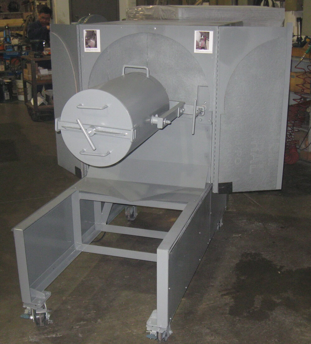
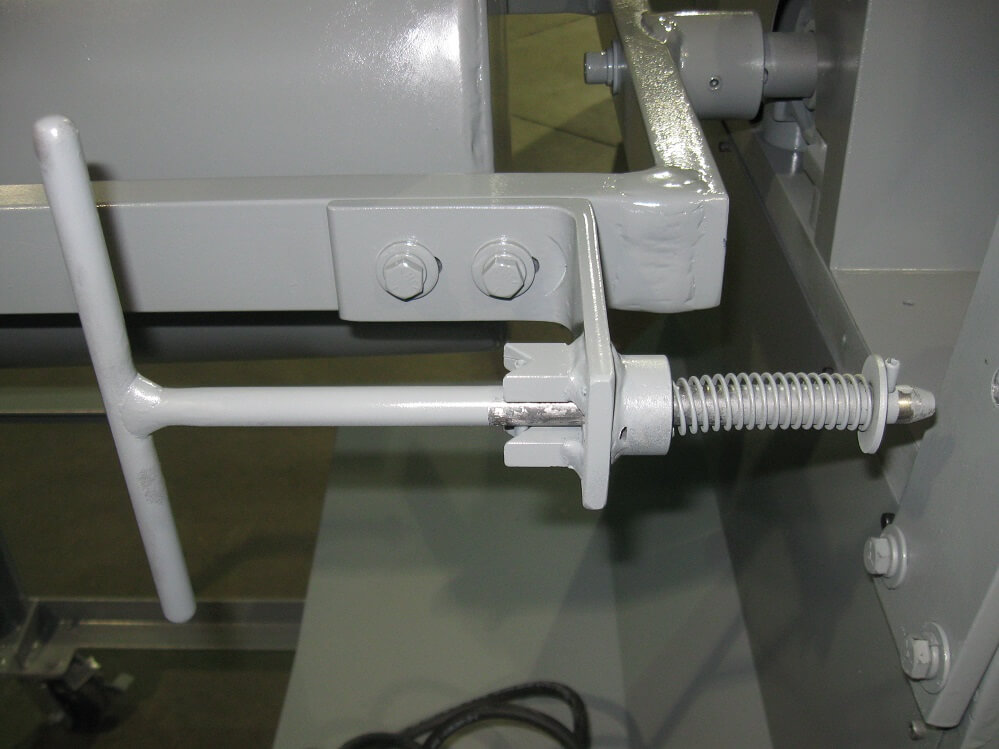
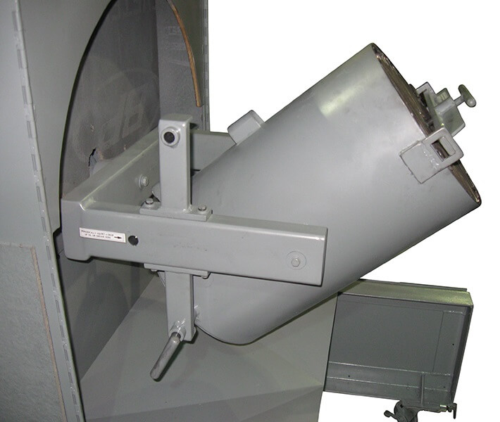
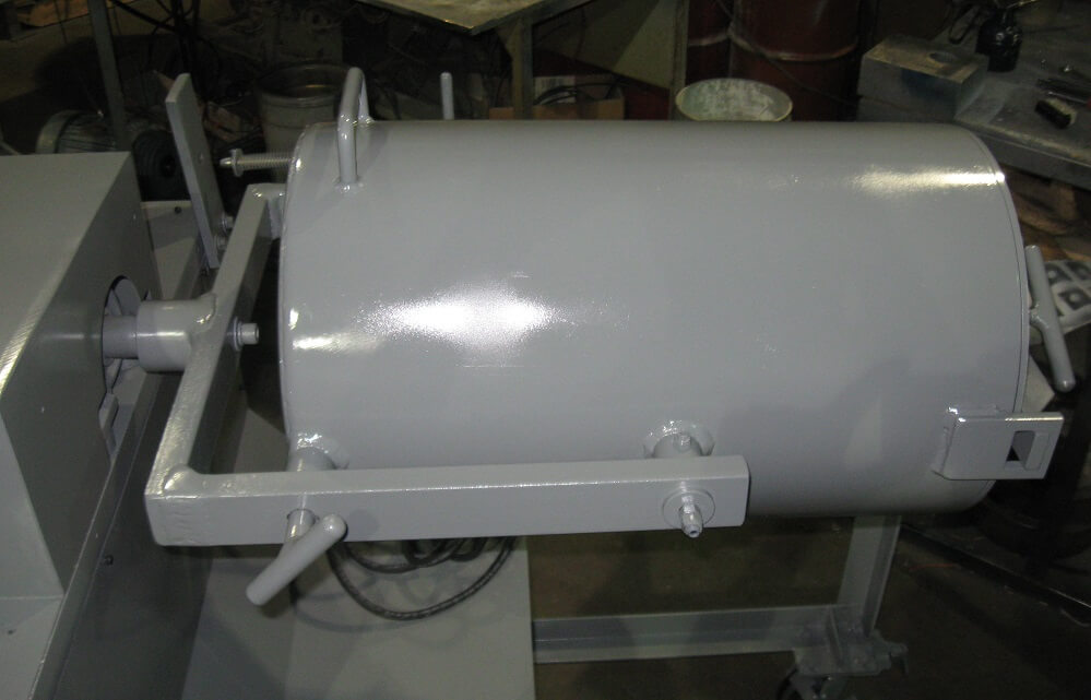
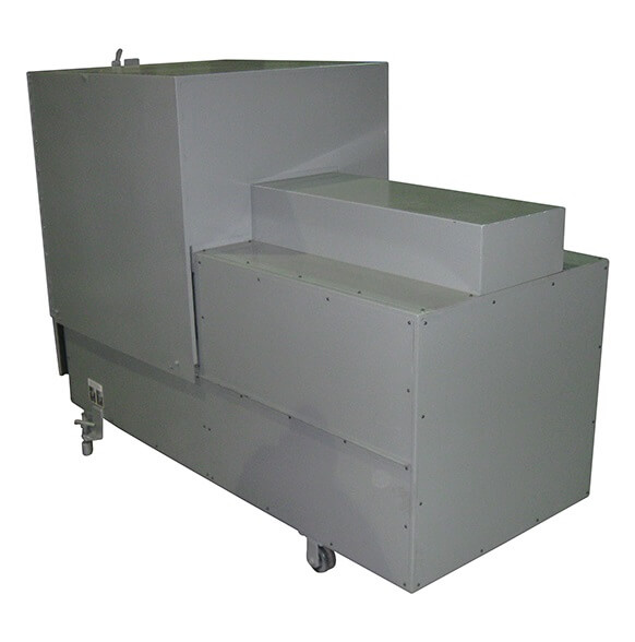
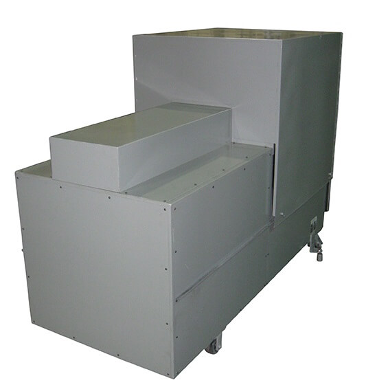
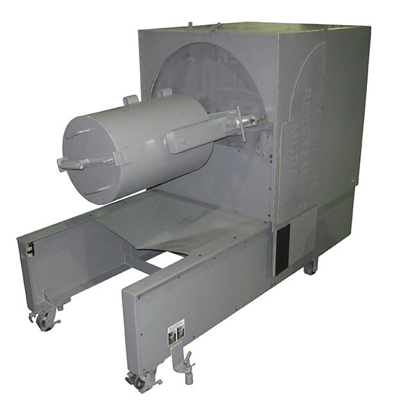
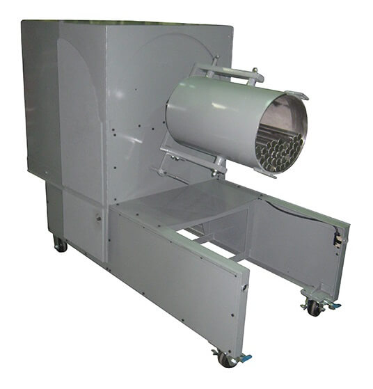
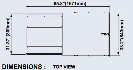
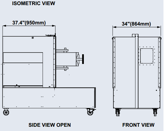
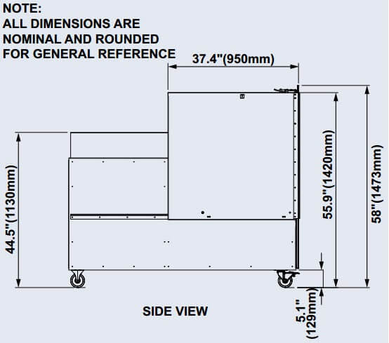
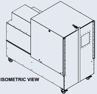
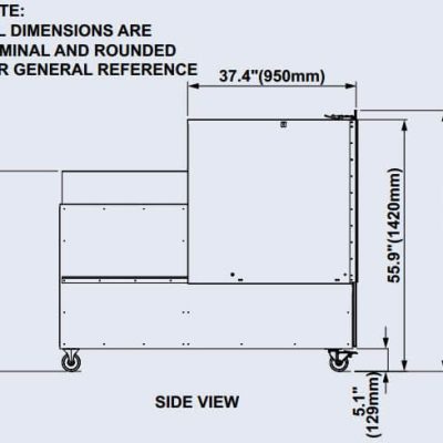
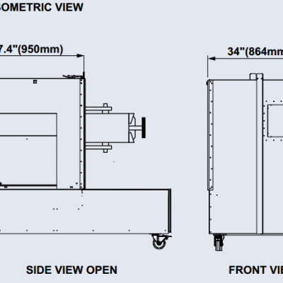
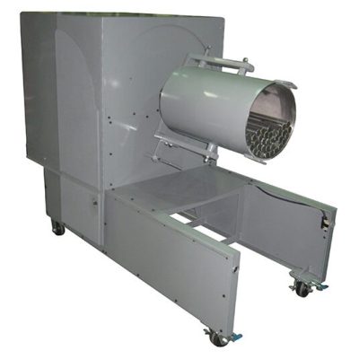
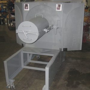
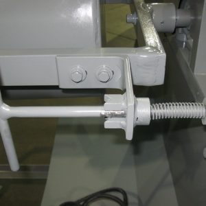
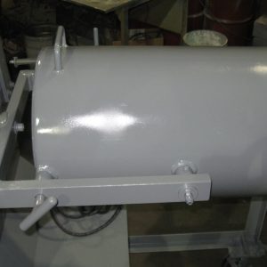
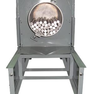
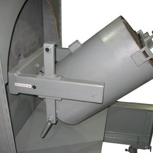
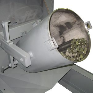
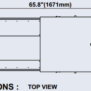
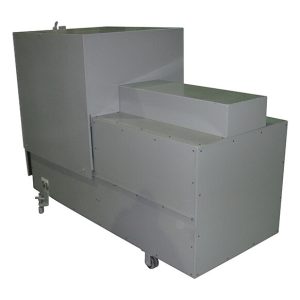
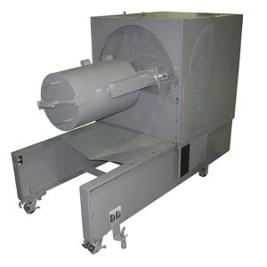
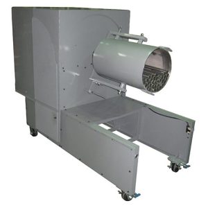
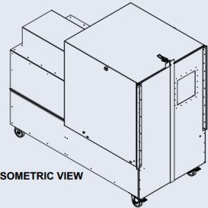
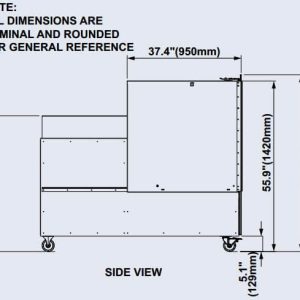
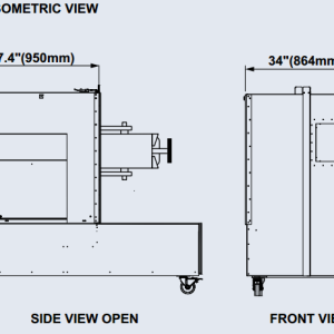
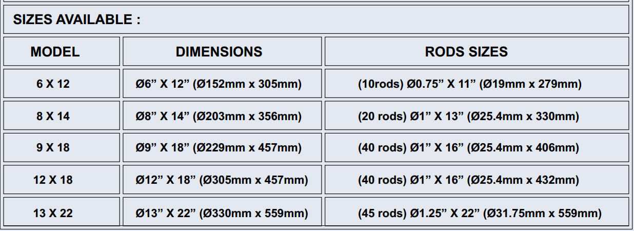
 Our Laboratory Grinding Mill comes standard with a 1 HP motor and optional variable speed drive ranging from 1 to 100 RPM. This Grinding Mill is fully enclosed with sound dampening material for a quiet workplace. The sheet metal steel fabrication provides full enclosure around the main frame and door. The yoke (grinding cylinder) is totally balance and vibration-free in its horizontal position of operation. Minimal effort is needed to swing it from horizontal to vertical position (loading/unloading). A unique feature this grinding mill has is the possibility to use different cylinders for research or pilot plants tests. Specifically, we offer different size of cylinders from 5” (127mm) inside diameter by 12” (305mm) long to 9” (229mm) diameter by 22” (560mm) long. All grinding mill’s cylinders can be mounted/removed rapidly. Grinding cylinders are interchangeable from large to smaller cylinders if desired. The cover is of a unique design that automatically seals the cylinder and is quickly mounted/removed. Another feature of this grinding mill are its heavy duty castors (wheels) for ease of laboratory movement/mobility.

