Table of Contents
- The Fluorspar Beneficiation Problem
- A Fluorspar Flotation Process Flowsheet
- Production of Acid Grade Fluorspar
- The Acid Grade Fluorspar Problem
- Difficult Flotation of some Flourspar Ore
- The Difficult Metallurgy Problem
- The More Complex Treatment Flowsheet
- Design Study for 125-Ton Fluorspar Mill
- Fluorite Beneficiation Process
- FLUORSPAR GEOLOGY
The Fluorspar Beneficiation Problem
Acid grade fluorspar which is in great demand by the chemical and aluminum industries, must contain at least 97.5% CaF2 with not more than 1.5% SiO2 and 0.5% Fe2O3. Often the Silica is limited to 1.2% with penalties starting at 1.0% SiO2. These limitations on grade and impurities require extremely close mill control, particularly through flotation where selectivity and high recovery is essential.
Over 95% of all acid grade fluorspar is processed by flotation through “Sub-A” (Fluorspar Type) Flotation machines. These machines, of the cell to cell type, are designed special for fluorspar with a high degree of flexibility essential for selectivity and multiple cleaning of concentrate. Middlings and clean tailings often must be completely isolated from the separate cleaning steps and diverted to the proper part in the milling circuit for most economical and efficient retreatment.
A Fluorspar Flotation Process Flowsheet
The flowsheet illustrated above is typical for the average “Sub-A” Fluorspar Flotation mill treating up to 100 tons of mine run ore per 24 hour day. Actual flotation conditions and equipment requirements should always be determined by having a comprehensive test made on the ore before proceeding with any fluorspar operation. Fluorspar ores may be quite complex, particularly when associated with lead and zinc sulphides, barite, calcite, iron oxide, and siliceous impurities. For this reason, a laboratory flotation test should be the first step in establishing a flowsheet.
Crushing Fluorspar Ore
For the average small mill treating up to 100 tons of ore a day, primary crushing is usually adequate and very economical. Larger tonnage will require primary and secondary crushing for maximum efficiency in size reduction and subsequent ball milling.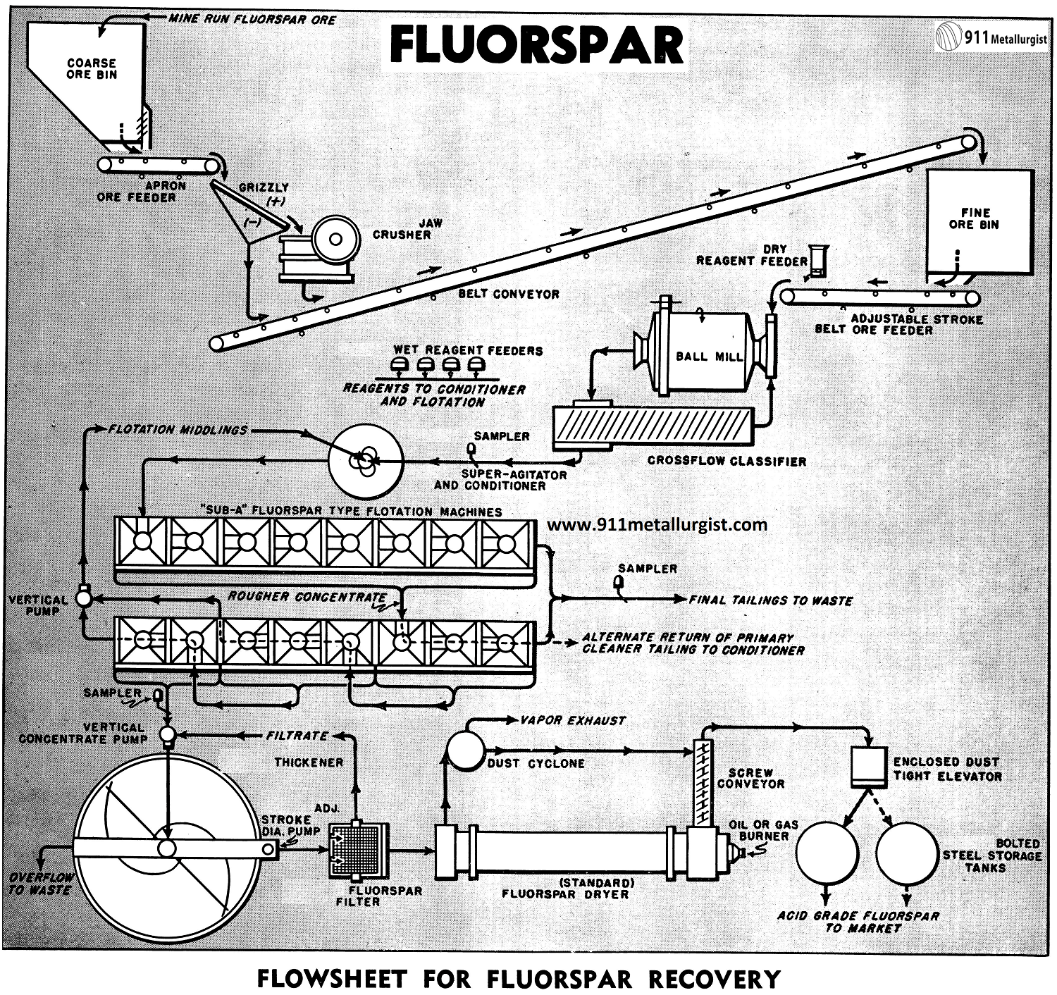
Grinding Circuit
Fluorspar ores usually require grinding to 48 or 65 mesh to liberate the calcium fluoride from the gangue impurities.
Ball mill grinding with a Steel Head Ball Mill in closed circuit with classifier is the general practice. In larger plants, particularly when fine grinding is necessary, thickening of the classifier overflow is necessary to maintain proper density and feed regulation to flotation. This thickening step on fluorspar ores containing sulphides is usually between the sulphide and fluorspar flotation circuits. Reagents used for selective flotation of lead and zinc then can be rejected in the thickener overflow water.

Pulp Conditioning
Normally, conditioning at mill temperature will thoroughly film the fluorspar with reagent and make it readily amenable to separation and recovery by flotation. Heating the pulp, even up to the boiling point, is often advantageous.
An Agitator and Conditioner is ideal for fluorspar conditioning as circulation is positive and thorough reagentizing with a minimum amount of reagent is assured. Any frothing tendency is dissipated in the pulp through the stand pipe and adjustable froth collar.
Fluorspar Flotation
Flotation of fluorspar must be extremely selective when producing acid grade concentrate. This selectivity is essential as the ratio of concentration is low, often up to 80% or more of the entire tonnage, and must be floated in the rough circuit. Cleaning by two or more stages of flotation must bring the rougher product up to acid grade and at the same time retain a high weight recovery with a minimum circulating load.
The “Sub-A” Flotation machine, the accepted standard in all fluorspar flotation plants, has been adapted specially for fluorspar treatment with provision for multi-stage cleaning and recirculation of middling products without the need of auxiliary pumps. Cleaner tailings may be conveniently removed at any point in the circuit. The flowsheet on the reverse side of this page shows one of the many possible cell arrangements used in treating fluorspar ore.
Thickening and Filtering
Thickening of fluorspar concentrates offers no special problem. Thickener capacity, however, should be adequate to handle the tonnage and have ample storage capacity during possible interruption in the filtering and drying sections. Fluorspar flotation froth has a tendency to build up on the thickener surface, but this can be taken care of by retaining rings near the overflow lip and by sprays so only clear water overflows the thickener. Thickened concentrates at 50 to 60% solids is removed by a Adjustable Stroke Diaphragm Pump, feeding by gravity to the filter.
Fluorspar is extremely rapid filtering even when ground fine, provided a non-blinding filter media is used. The rotary fluorspar type filter with stainless steel filter media, heavy duty oscillating mechanism, oversize valve and ports, and high displacement vacuum pump is standard for fluorspar flotation concentrates and will discharge a filter cake with as low as 6% moisture. In the event the filtrate is slightly turbid or contains solids, it should be diverted back to the thickener. For this reason a adjustable stroke diaphragm pump is often used in place of the conventional centrifugal filtrate pump.
Drying and Storage
Fluorspar flotation concentrates of acid grade must be dried to less than 0.5% moisture. Dust losses are kept to a minimum by providing a closed system with a cyclone to insure only vapor laden air discharging to the atmosphere. Enclosed screw conveyors, elevators and often air-born systems are used to transport the finely divided dried acid spar to the storage bins. Provisions should be made for handling efficiently the hot concentrate discharging from the dryer. The Standard Dryer is ideal for this purpose.
Typical equipment list for a 100 ton per 24 hour acid grade fluorspar flotation plant producing 50 tons of concentrates per day when grinding a medium soft ore to 48 mesh.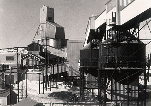
Production of Acid Grade Fluorspar
The Acid Grade Fluorspar Problem
Fluorspar ores often contain appreciable amounts of sulphides in the form of galena, sphalerite, or both. These sulphides, when present, not only represent a valuable constituent of the ore, but also must be removed prior to fluorspar flotation to meet the market specifications for acid grade fluorspar.
The acid grade concentrate must contain a maximum of 0.2% lead, 0.2% zinc, and 0.03% sulphide sulphur or free sulphur in combination with these, or separate.
The problem is some what more complex when sulphides are present, and certain provisions must be made in the flowsheet to effectively remove the sulphides.
In addition to lead present as the sulphide, it may exist in oxidized form as a cerussite or anglesite, and require sulphidization to remove prior to the fluorspar flotation.
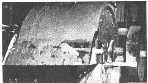
Fluorspar Filter has special oscillating agitator in tank to keep fluorspar in suspension.
The Acid Grade Fluorspar Flowsheet
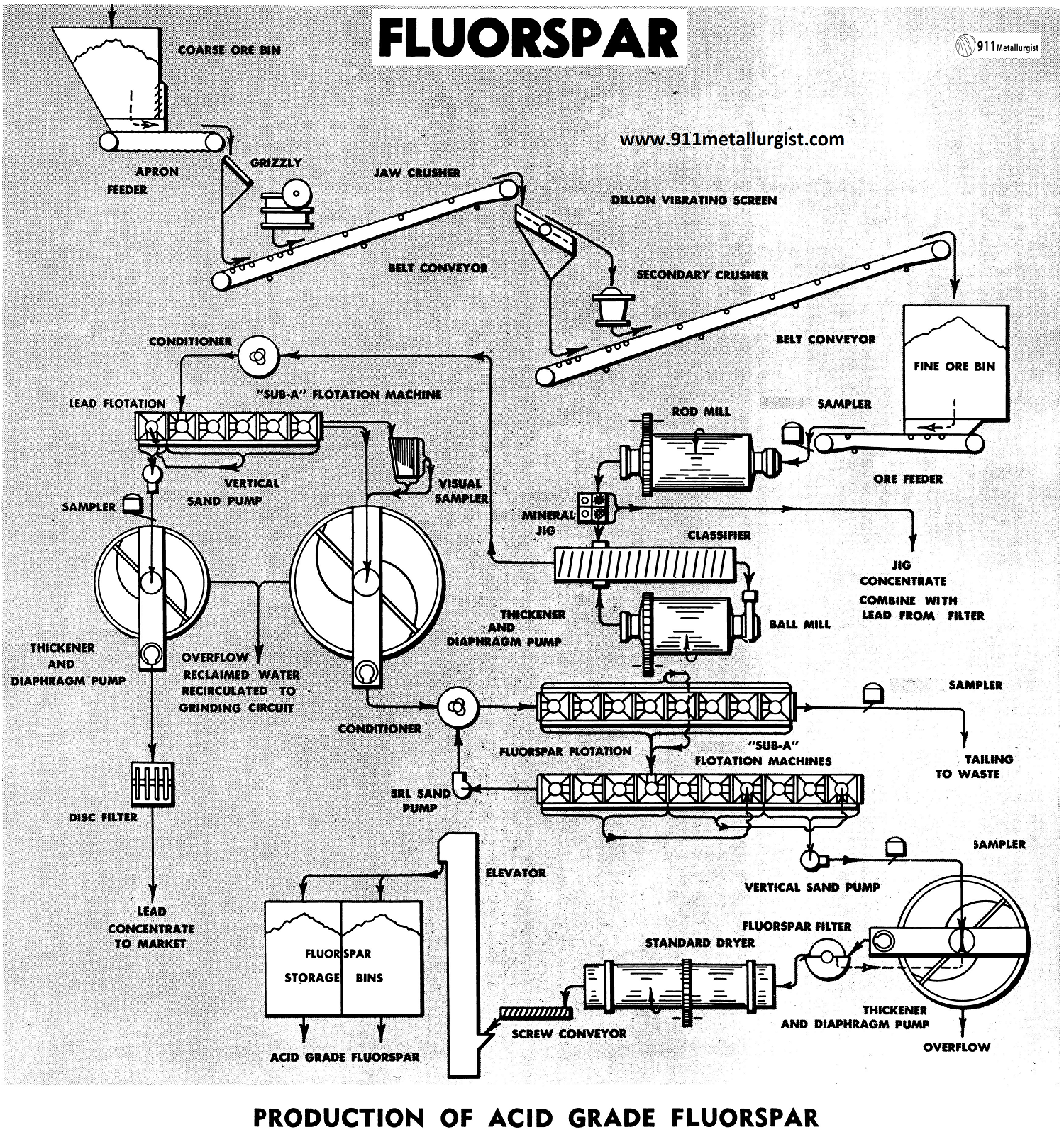
The flowsheet shown is of a conventional type, for treatment of 200-300 tons per day of fluorspar ore containing lead, using “Sub-A” Flotation.
If lead and zinc were present, the same flowsheet would apply to remove a bulk sulphide concentrate which could be subsequently refloated to produce the respective lead and zinc concentrates suitable for marketing.
The best approach to effectively produce separate lead and zinc concentrates should be established by test work. In some cases, selective flotation is indicated initially. This may be accomplished by removing a lead concentrate, then following this process by conditioning and flotation of the lead tailing to produce a zinc concentrate.
Crushing Circuit
Primary and secondary crushing are used for this plant tonnage. Single stage crushing may be employed for tonnages up to 100 tons per day.
Grinding Circuit
Two stage grinding, using the Rod Mill in open circuit, followed by closed circuit ball mill grinding, is ideal because of the local power requirement and the increased efficiency of grinding.
The Selective Mineral Jig may be utilized to recover galena in this circuit. Presence of oxidized lead in the ore is overcome to a great extent by removing it at a relatively coarse size, in the jig.
Conditioning Tank
Conditioning of the classifier overflow is required if sulphidization is employed to effect flotation of oxidized lead. A second stage conditioning of the thickened lead tailing, after repulping with fresh water, is required for flotation of the fluorspar. Heating of the pulp at this point is often advantageous.
Fluorspar Flotation
The lead and fluorspar are recovered by Flotation of the cell-to-cell type, permitting maximum recovery and grade of concentrate. Wide acceptance of machines is well verified when considering that over 95% of all acid grade fluorspar is processed in the “Sub-A” Flotation Machine. Flexibility of these machines is of prime importance where such high specifications must be met. Multiple cleaning, always necessary in acid grade fluorspar plants, can be performed without the help of pumps.
Lead tailing is thickened to remove the bulk of the reagents used in the lead circuit. The clear overflow is re-circulated to the grinding circuit.
Thickening and Filtering
Both concentrates are thickened and filtered. The thickened lead concentrate is filtered on the Disc Filter. Thickened fluorspar concentrate, at approximately 60% solids here, has a high filter capacity of approximately 2000 pounds per sq. ft. per 24 hours. The Fluorspar Filter with its stainless steel filter media, is especially designed for this application.
Drying and Storage
The Standard Dryer effectively dries the filtered fluorspar concentrate to less than 0.5% moisture, as required for marketing. An elevated temperature in the dryer can also be used to burn off small amounts of sulphur and lead.
A screw conveyor and bucket elevator as employed to transport the dried fluorspar to the concentrate storage bins. Bins can be conveniently discharged into rail road cars for shipment, while the filtered lead concentrate may be marketed as produced, without drying.
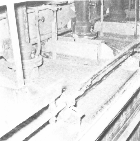
“Sub-A” Flotation Cells in a Fluorspar Mill.
Difficult Flotation of some Flourspar Ore
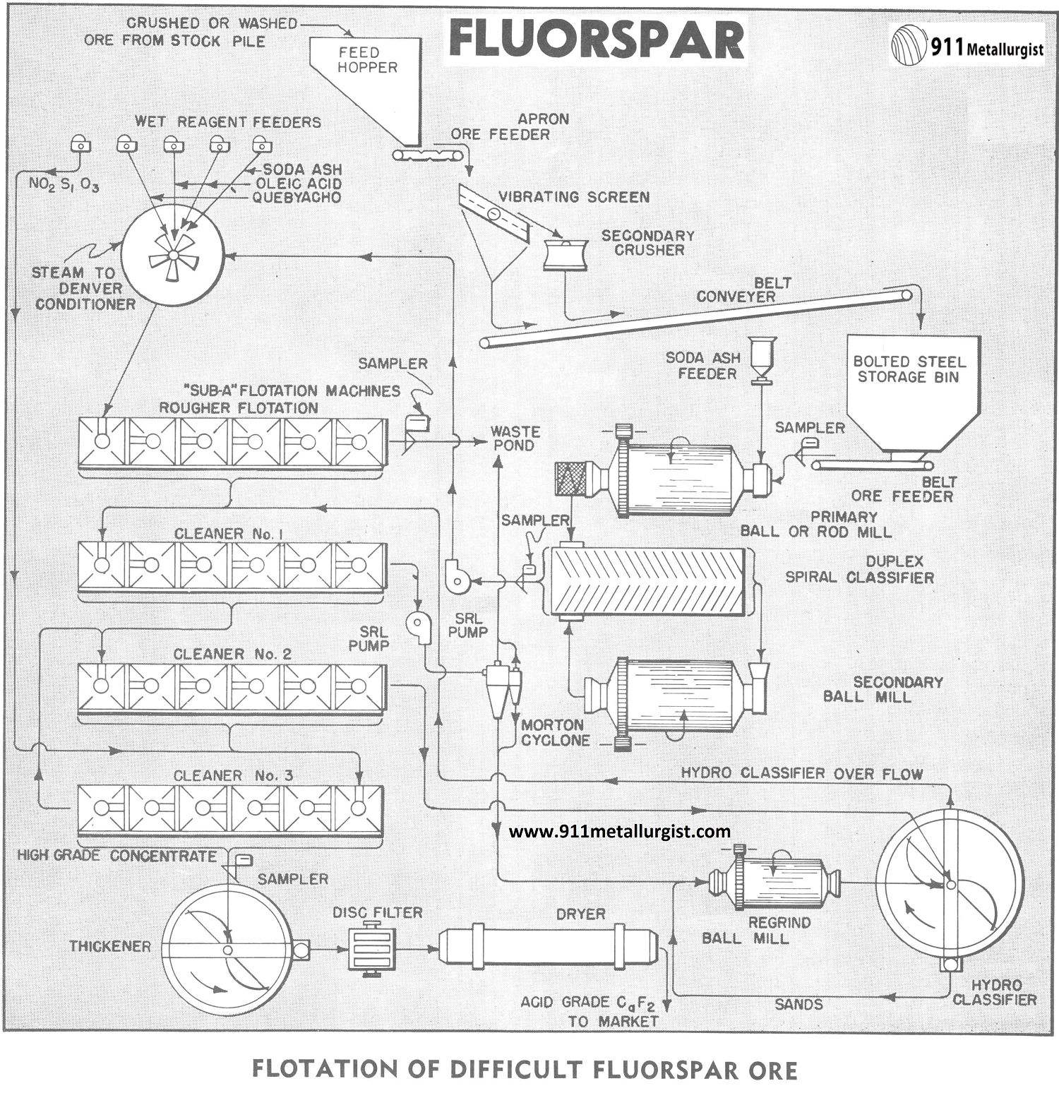
The Difficult Metallurgy Problem
While many ores respond to the same general pattern of treatment, each ore is an individual problem. Such is the case of this fluorspar ore which is characterized by the presence of a portion of the fluorite in extremely close association with calcium carbonate and silica and containing appreciable clay.
High acid grade fluorspar concentrates are difficult to obtain from this class of ores by flotation with an ordinary -65 mesh grind. The concentrates, in this study, are currently being used for production of hydrofluoric acid and synthetic cryolite. Market requirements demand that the calcium carbonate content be reduced to an absolute minimum. Moreover, the future production now in demand, is desirable. This study deals with a flowsheet designed to achieve high recovery of acid-grade fluorspar in an economical manner.
The More Complex Treatment Flowsheet
The typical fluorspar flotation flowsheet normally consists of stage grinding by ball mill in closed circuit with a mechanical classifier followed by conditioning of the pulp either with or without steam in the presence of reagents followed by “Sub-A” Flotation with three or more cleaning steps by reflotation. This particular ore does not, with the normal flowsheet, produce an acid grade concentrate of 97.5% CaF2 with less than 1.5% SiO2.
” The ore being studied is crushed underground at the mine and partially beneficiated by the heavy media process. This washed ore is further crushed at the mill. Soda ash is added to the primary grinding mill which is in open circuit with a duplex Spiral Classifier. The classifier is in closed circuit with the secondary grinding mill and the classifier overflow, which is all — 65 mesh, is pumped by a SRL Pump to the Conditioner where the following reagents are added:
Reagent Amount, Pounds per ton
Na2Si03 (Optional) 0.2
Soda Ash 2.0
Oleic Acid up to 2.0
Quebracho 0.2
(Na2SiO3 is also added to the feed of the last cleaner flotation circuit and the effect of this reagent is utilized through the return of cleaner tailings to the head of the circuit.)
Conditioning time is 8 minutes at a pulp density of 40% which is then adjusted to 30% for flotation. Steam coils in the conditioner maintain the pulp at 170 degrees F. prior to flotation.
The conditions presented by this particular ore illustrate the importance of complete laboratory investigations as a great many different combinations of treatment were required to develop the final flowsheet. The deviations from the standard fluorspar flowsheet were first substantiated by locked cycle batch laboratory tests followed by a small tonnage pilot plant run to verify the laboratory results before final recommendations were made.
The rougher flotation circuit produces a final tailings while the rougher concentrate is subjected to the first cleaning stage. A 6 – cell “Sub – A” Flotation Machine, cell – to – cell type, is used for the rougher flotation and 6-cell “Sub-A” Flotation Machines are also used for the three cleaning steps.
Tailings from the first cleaners are pumped to a Morton 2-stage Cyclone for the removal of clay slimes. The ability to add clear water for washing in the classifier makes the Morton Cyclone particularly useful at this point in the flowsheet. The slimes go to final tailings and the cyclone sands, at high density, are reground in a Regrind Mill which is in closed circuit with a Hydro-Classifier. The regrind is to —325 mesh and the hydro-classifier overflow returns to the first cleaner cells for reflotation. Reagent sodium silicate is recommended to aid classification.
Concentrates from the first cleaners go to the second cleaner cells where further up-grading takes place.
The middlings (tailings) from the second cleaner cells go to the hydro-classifier in the re-grind circuit. The concentrates from the second cleaners advance to the final cleaners. Tailings from the final cleaner cells are returned to the second cleaners and the final, high grade concentrates are filtered, dried and shipped to market.
FATTY ACIDS IN FLUORSPAR FLOTATION
The concentration of fluorspar ores for the production of acid grade concentrates is accomplished by the use of combinations of reagents such as pH regulators, depressant and fluorspar promoters. The reagents commonly used are as follows:
- Soda ash and caustic soda for pH control.
- Quebracho, Palcotan, sodium silicate and dextrine as gangue depressants.
- Fatty acids for the fluorspar promoter.
The following are some of the most commonly used fatty acid promoters:
- Aero Promoter 765 — American Cyanamid.
- Crofatol No. 1 — Crosby Chemicals, Inc.
- Emersol 233LL — Emery Industries.
- Emerson 300 — Emery Industries.
- Acintol DLR — Arizona Chemical Company.
- Aliphat 44E — General Mills.
- Red Oil low titre — Armour & Company.
- Oleic Acid.
In general the fatty acids which have a low rosin, high oleic acid content and low titre are desired due to their greater selectivity.
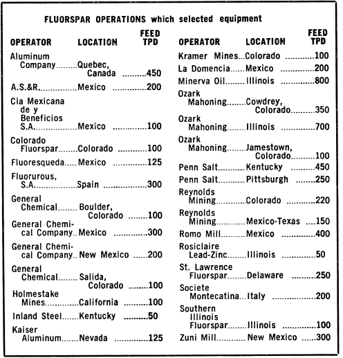
Design Study for 125-Ton Fluorspar Mill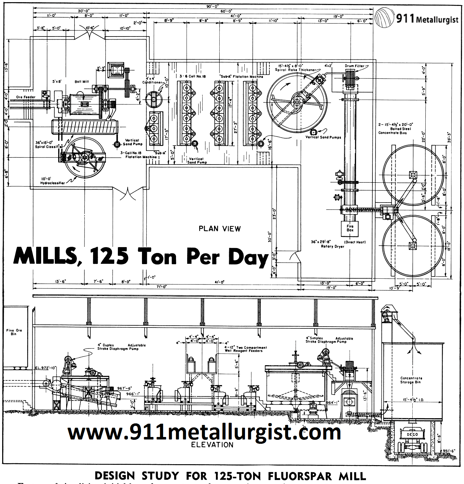
Factors of simplicity, initial low plant cost, together with flowsheet flexibility for maximum results on a difficult ore were basic considerations in the design of this 125-ton per day Fluorspar Flotation Mill. The design proved successful and accomplished the desired metallurgical results, with low capital expenditure and operating costs.
Tin Process Flowsheet
Following numerous laboratory tests, a flowsheet was developed that gives flexibility to handle the several types of fluorspar ores. Two stage open circuit crushing, with the average ore ground to 100 mesh,gives maximum results. Fine grained ores with some sulphides require secondary classification and a sulphide flotation stage. Due to character of most fluorspar ores heating the pulp gave improved results, and necessitated the installation of a boiler to provide hot dilution and make up flotation water for five stages of cleaning and recleaning. A Apron Feeder controls the feed from crude ore bin to jaw crusher while a wedge bar grizzly ahead of the jaw crusher removes the fines from the crusher feed. A 2’x4′ Dillon Screen removes the fines ahead of secondary crushing. An adjustable stroke ore feeder controls feed to the 5’x8′ Steel Head Ball Mill, and the spiral classifier discharge is pumped direct to flotation section or to hydroclassifier for secondary classification, depending on requirements.
Concentrator Site
The mill site, 12 miles from the mine, was selected because of:
- Availability of ample water and power.
- Topography of Mill Site provides gravity flow—minimum use of pumps, and minimum of excavation, retaining and foundation walls. The important part in any mill-site is to be sure that the maximum use of cut and fill is utilized. Concrete is expensive and is primarily considered for adequate foundation instead of expensive retaining walls and fills.
- Adequate tailings disposal—with minimum maintenance.
- Accessability for operating labor and supplies and trucking, etc.
- Use of minimum of labor in erection.
- Availability of natural timber.
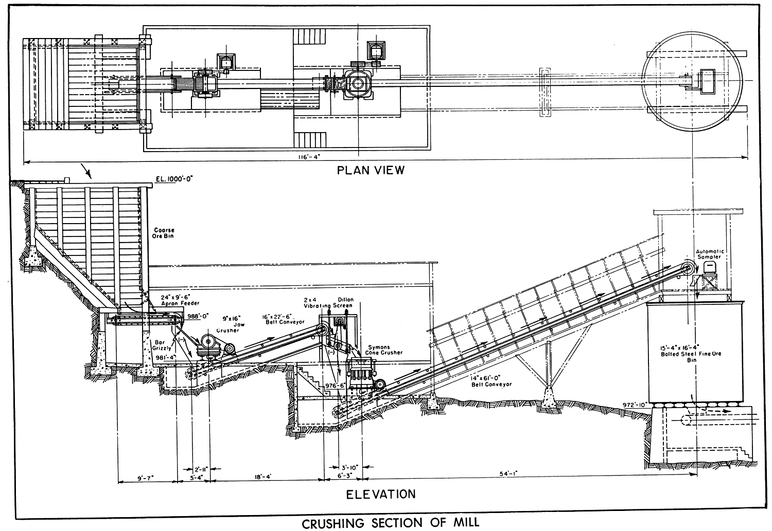
Process Plant Design
The machinery was located for accessibility, ease of operation, minimum loss of floor space, resulting in reduced size of mill. The crude ore bin was constructed of natural timber on the site, on a steep slope, reducing expense of excavation and construction. An 8″ clear opening rail grizzly prevented oversize going into bin.
The flotation machines are mounted on natural timber supports, at minimum elevation with space platforms for drainage of machines and pipelines.
The buildings for crushing section and mill are of light steel construction with corrugated sheet metal on walls and roof. The frame work and trusses lightweight for building support only and provided without insulation, because of mild climatic conditions. Account of heavy snowfalls the roof slopes are all of quarter pitch.
Roof ventilators and steel sash windows are provided, and conveyor ways have bar size angle wall and roof supports covered with corrugated sheet metal.
Launders on cleaning stages are made so that flows can be changed to regulate number of cells required, depending on the type ore being treated. Wood platforms and walkways of 2″ spaced lumber are used in flotation sections, while piping between machines is carried below the floor.
All electric lighting and power wiring with ample reserve are in rigid conduit with flexible connections to motors; and motor controls are mounted on wall panels with stop and start push button stations located within sight or near each motor. Fluorescent lighting is provided over flotation section, as it gives operators better visual control of the flotation operation. The Rotary Dryer is lined with fire brick at discharge (burner) end.
This design resulted in comparatively low initial plant cost and gave efficient operating results. Proper planning proved worth while in reduced operating costs and increased operating profits.
Fluorite Beneficiation Process

Fluorite Production Problems
With depletion of high-grade deposits, production must depend upon low-grade deposits that are highly contaminated with impurities which may be silica, calcite, barite, iron oxide, and sulphides such as pyrite, galena, and sphalerite, in close association. The flotation problem is largely one of impurity removal. The sulphide minerals are generally floated first, and then the fluorite is floated from the silica, calcite, and other impurities.
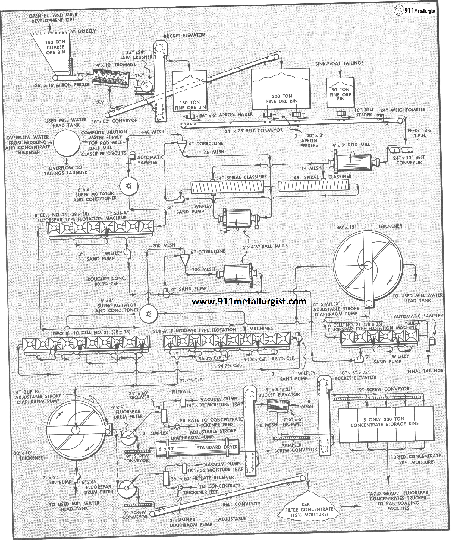
Fluorite Reagent Combinations
Oleic acid or various mixtures of oleic and linoleic acids with soda ash and sodium silicate as silica depressant and slime controller, and quebracho to depress calcite, are the common reagents for fluorspar flotation. Sometimes pre-sulphide flotation with xanthate and a frother is necessary to remove sulphides and, often, heating the pulp to boiling temperature is advantageous in effectively depressing the silica, calcite and other associated minerals in the cleaning stages.
FLUORSPAR GEOLOGY
[/fusion_builder_column][fusion_builder_column type=”1_1″ background_position=”left top” background_color=”” border_size=”” border_color=”” border_style=”solid” spacing=”yes” background_image=”” background_repeat=”no-repeat” padding=”” margin_top=”0px” margin_bottom=”0px” class=”” id=”” animation_type=”” animation_speed=”0.3″ animation_direction=”left” hide_on_mobile=”no” center_content=”no” min_height=”none”]
Source: This article is a reproduction of an excerpt of “In the Public Domain” documents held in 911Metallurgy Corp’s private library.
Flotation of a Fluorspar Ore from Illinois
This report is the fourth in a Bureau of Mines series describing the sodium fluoride-lignin sulfonate-fatty acid process of froth flotation separation of fluorspar from complex ores containing fluorspar, barite, calcite, and quartz which was developed and patented by Clemmer and Clemmons of the Bureau of Mines. At the Tucson (Ariz.) Metallurgy Research Laboratory the ores of Arizona were studied; and at the Tuscaloosa (Ala.) Metallurgy Research Center, the ores of Kentucky, Tennessee, and Illinois were studied.
The sodium fluoride-lignin sulfonate-fatty acid process is applicable to a variety of ores of different grades and mineral association for recovery of fluorspar from associated gangue materials; it has been shown to be practicable in continuous pilot plant operation as well as laboratory-scale flotation tests. This report deals with the application of the process to a complex calcareous fluorspar ore from Illinois and presents the results of laboratory batch flotation tests and continuous pilot plant flotation tests for recovery of the fluorspar in the ore.
The largest use of fluorspar is in the production of hydrofluoric acid in which no satisfactory substitute for acid-grade fluorspar is known. A prospective new outlet for hydrofluoric acid is in its addition to the oxidizer of the Atlas rocket, which will significantly increase the booster performance. The second major use of fluorspar is as a flux in the manufacture of basic open hearth and basic electric furnace steels in which no suitable materials are available to replace metallurgical-grade fluorspar, A third use of fluorspar is in the manufacture of glass and ceramic products. The specifications and prices of the various grades of fluorspar are listed in appendix A.
Description of the Samples
The complex fluorspar ore used in the investigation was from the fluorspar district near Cave-in-Rock, III. ; a 14-ton sample of ore was obtained from the Minerva Co. Crystal mine located about 5 miles west of Cave-in-Rock.
Petrographic examination showed that about 38 percent of the fluorspar reporting to the minus 48- plus 65-mesh fraction contained inclusions and that about 24 percent of the fluorspar was locked in the minus 325- plus 400-mesh fraction. However, the carbonate and quartz crystals locked in the fluorspar mineral were extremely small; in a concentrate analyzing 98.0 percent CaF2, 30 percent of the fluorspar grains were locked. The petrographic analysis revealed that no appreciable benefit to mineral liberation would be achieved by crushing finer than 65 mesh.
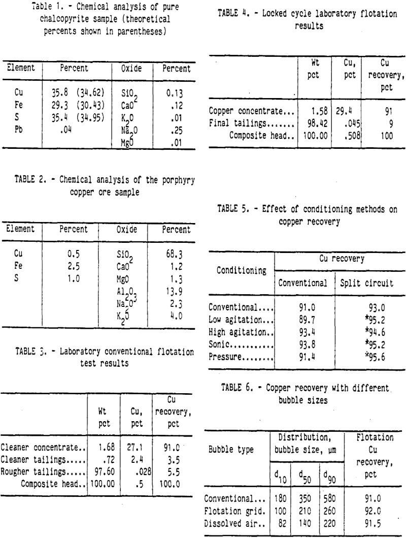
The primary carbonate in the ore was calcite with a considerable quantity of dolomite. The silica present was reported as quartz. Other materials consisted of 1.3 percent sphalerite and minor amounts of barite and galena. A chemical analysis of the sample is shown in table 1.
Experimental Results
Laboratory Batch Flotation Tests
Samples of the ore were prepared for flotation by dry crushing to minus 10 mesh followed by wet stage grinding to minus 65 mesh in a laboratory pebble mill, using Tuscaloosa city tap water that had about 45 parts per million equivalent calcium carbonate total hardness. Prior to flotation, the ground ore pulp was treated, at about 40 percent solids, in a mechanically agitated flotation cell with conditioning reagents and then with a collector. A rougher fluorspar concentrate was floated off and cleaned six times.
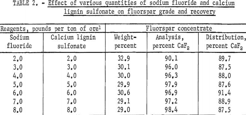
A series of preliminary flotation tests was made of the ore to determine the quantities of sodium fluoride and calcium lignin sulfonate necessary to produce the maximum recovery and grade of fluorspar. The quantities of sodium fluoride and calcium lignin sulfonate were varied from 2.0 to 8.0 pounds per ton of ore; the quantity of oleic acid was held constant at 0.48 pound per ton of ore. The grade of fluorspar concentrate was increased with the dosages of sodium fluoride and calcium lignin sulfonate and leveled off at 5.0 pounds per ton. The summarized results of flotation tests made to determine the effect of varying the quantities of sodium fluoride and lignin sulfonate are given in table 2.
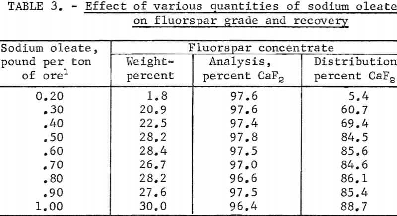
The laboratory batch flotation studies were continued to determine the optimum quantity of collector needed to obtain the maximum grade and recovery of fluorspar. The pulp was conditioned (1) with 5.0 pounds of sodium fluoride per ton of ore. to disperse the pulp and clean up the mineral faces, (2) with 5.0 pounds of calcium lignin sulfonate per ton of ore to coat the surfaces of the gangue particles and render them hydrophilic, and (3) with various quantities of sodium oleate, as a collectors to concentrate the fluorspar. In most instances an acid-grade fluorspar concentrate was obtained. The rougher concentrate contained 94.3 percent of the total fluorspar in the ore at a collector dosage of 0.30 pound per ton of ore, but the mineral particles did not adsorb enough collector to sustain their flotation during the six cleaning stages. About 0.50 pound of collector per ton of ore appeared to be the optimum dosage; the grade and recovery of fluorspar were essentially constant with larger quantities. This indicated that large quantities of sodium oleate were adsorbed by the fluorspar mineral and not by the gangue materials. The summarized results of these tests are shown in table 3.
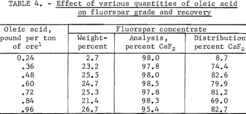
Another series of tests was made using various quantities of oleic acid as the collector while maintaining the quantities of sodium fluoride and calcium lignin sulfonate at 5.0 pounds per ton of ore. The tests revealed that the oleic acid was as selective as the sodium oleate in producing acid-grade fluorspar concentrates ; however, the fluorspar recovery was somewhat lower with the oleic acid because it did not disperse, as well. The optimum amount of oleic acid was 0.48 pound per ton of ore. The summarized results of these tests are shown in table 4.
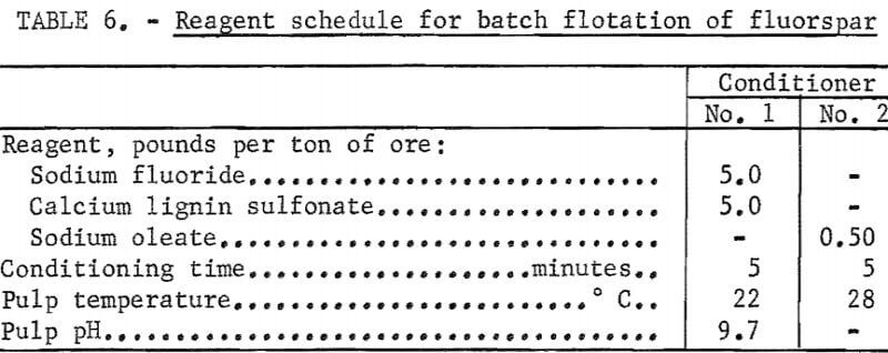
Additional laboratory batch flotation tests were made using the data obtained in determining the optimum quantities of reagent. The minus 65-mesh pulp was conditioned at about 40 percent solids in a mechanically agitated flotation cell for 5 minutes with 5.0 pounds each of sodium fluoride and calcium lignin sulfonate per ton of ore for dispersion of pulp and retardation of gangue minerals. Sodium oleate, 0.5 pound per ton of ore, was then added as a collector; conditioning was continued for another 5 minutes. The rougher concentrate was floated and refloated (cleaned) six times to remove gangue minerals. A concentrate analyzing 97.8 percent CaF2 and accounting for a fluorspar recovery of 84,5 percent was obtained. The results of a selected test are presented in tables 5 and 6.
Continuous Pilot Plant Flotation Tests
Based on the results of the laboratory batch tests, a continuous pilot plant with a capacity of about 150 pounds of dry feed per hour was assembled. The process included grinding, classification, conditioning, and flotation, as shown by figure 1.
The ore was reduced by jaw and roll crushers in closed circuit to minus 3/8 inch and stored in a bin. From the bin it was transferred by a constant-weight feeder to a rod mill operated at 60 percent solids. The rod mill operated in closed circuit with a vibrating screen to grind the ore to minus 65 mesh. The screen undersize (minus 65-mesh) passed to a hydroseparator for
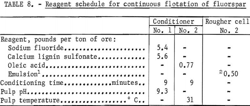
removal of colloidal slimes. The hydroseparator overflow represented about 1.5 percent of the weight of the ore and a loss of less than 1 percent of the total fluorspar. The hydroseparator underflow, at about 40 percent solids, passed to a conditioner where sodium fluoride and calcium lignin sulfonate were added. The discharge from the first conditioner flowed to a second conditioner where oleic acid was added as the fluorspar collector. A retention time of about 9 minutes in each conditioner gave satisfactory results. The conditioned pulp then flowed to a bank of three rougher flotation cells where a rougher concentrate was floated. The rougher tailing flowed to a single cell operating as a scavenger to recover additional fluorspar. The froth from this cell was recycled to the last rougher cell; the tails flowed to waste. The rougher concentrate was cleaned nine times, and the middlings were circulated back to the first cleaner where they were removed and thickened in a bank of three hydrocyclones (parallel). The underflow from the hydrocyclones was sent to the first conditioner, and the overflow went to waste. An emulsion-type collector (made up of 17.7 parts oleic acid 1.3 parts sodium oleate, and 361.0 parts water) was added to the second rougher cell to aid the flotation of the fluorspar.
The summarized results of a continuous flotation test are given in tables 7 and 8. The final fluorspar concentrate analyzed 96.4 percent CaF2 , a recovery of 90.0 percent of the total fluorspar in the ore. About 7 percent of the fluorspar was lost in the overflow from the cyclones.
The fluorspar concentrate was slightly below the specifications for acid-grade fluorspar; however, it meets all specifications for high-quality ceramic-grade fluorspar. It was possible to obtain an acid-grade fluorspar by introducing additional cleaners into the circuit; however, there was some sacrifice in recovery.
Conclusions
The laboratory batch and continuous pilot plant flotation tests demonstrated that the sodium fluoride-calcium lignin sulfonate-fatty acid method for selective flotation of fluorspar from complex calcareous fluorspar ore is an effective and practical means of producing high-grade fluorspar concentrates.
The flotation of the fluorspar in a continuous test in which the middlings were removed from the circuit, thickened, and returned for further conditioning produced a fluorspar concentrate analyzing 96.4 percent calcium fluoride, a recovery of 90.0 percent of the fluorspar in the ore. The fluorspar concentrate produced from a deposit near Cave-in Rock, III., meets all specifications for high-quality ceramic-grade fluorspar.
