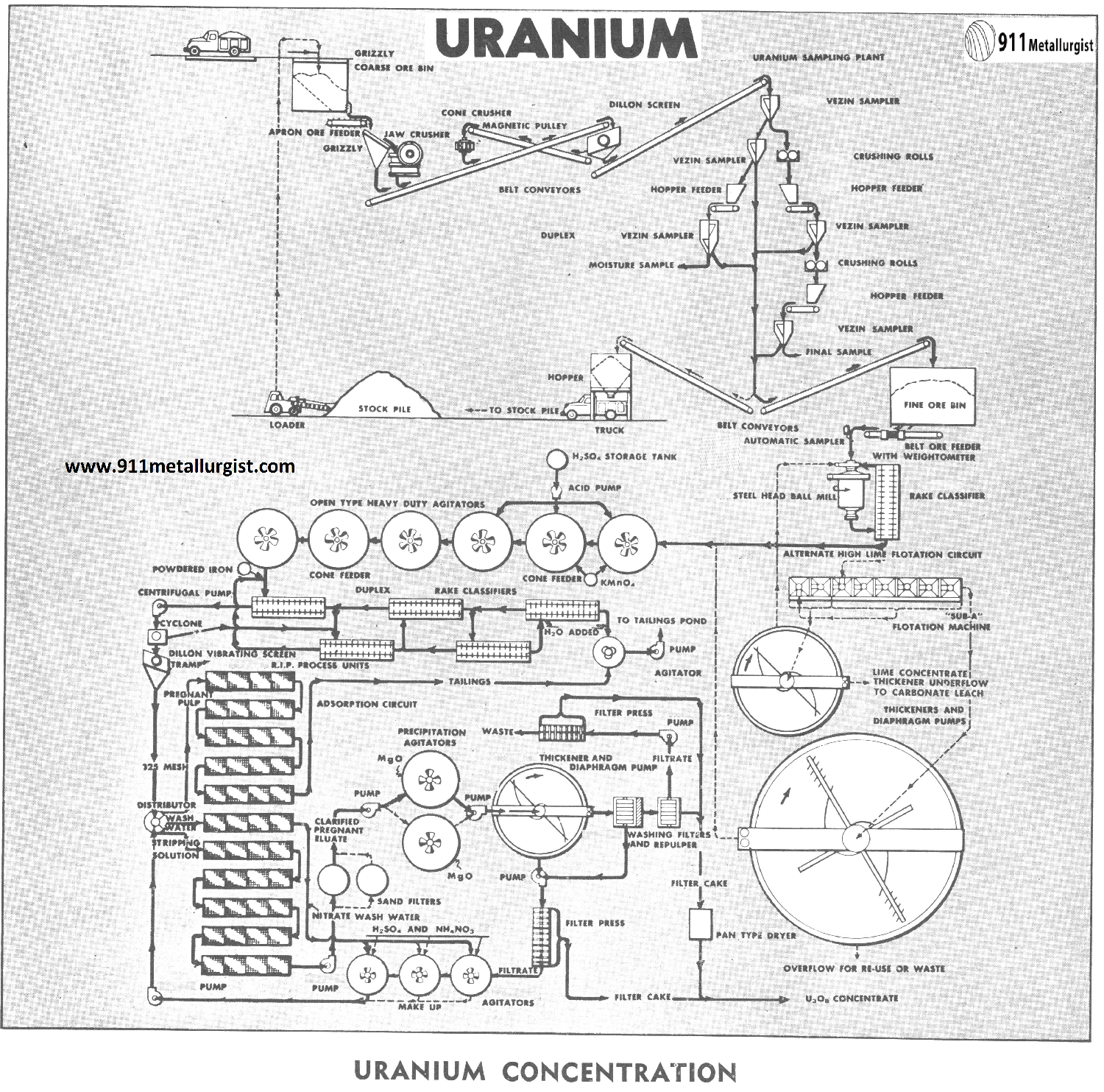
The process flowsheet of Uranium generally outlines the latest proven processes for uranium concentration known as “Resin In Pulp” more commonly referred to as RIP To date it is not applicable to ores containing vanadium, where the vanadium must be recovered.
Crushing Uranium Ore
Depending upon ore shipment schedules, it is desirable to operate the crushing and sampling sections on a 7½ hour per day basis.
Ore is delivered to the receiving hopper, which is provided with a grizzly. Feed to the primary Jaw Crusher is metered by a Apron Ore Feeder which discharges over a grizzly. The oversize is crushed and conveyed with the undersize from the grizzly to a Dillon Vibrating Screen. The screen scalps out the fines ahead of the secondary cone crusher.
A permanent magnet protects the secondary crusher from tramp iron. Closed circuit is preferred, as it minimizes the size of the primary sampler and possibly one stage of reduction in the sampling sections. Smaller tonnage mills can usually eliminate the secondary stage of crushing and feed material as coarse as 2″ to the rod or ball mill. This also depends on hardness of the ore.
Sampling for Uranium
Usually, the primary Vezin Sampler is furnished with two cutter openings, each of which allows a 10% cut.
Size reduction with Crushing Rolls or Jaw Crushers, and controlled feeding takes place between each stage of sampling. The secondary and tertiary Vezin Samplers are fitted with four cutters to enable the operator to obtain any quantity of sample desired, regardless of the size of shipment. The Coffee Mill makes the final size reduction.
Uranium Grinding and Classification
Ore is fed at a controlled rate by Adjustable Stroke or Variable Speed Ore Feeders. A weightometer records tonnage and a Automatic Sampler provides systematic sampling. Normal procedure in the RIP Process is to grind ores to —28 or —35 mesh in a Rod Mill or Ball Mill, which is operated in closed circuit with a Rake Classifier. Classifier overflow must be in excess of 50% solids due to subsequent acid leaching.

Uranium Lime Flotation Circuit
Acid leaching of high lime ores is extremely costly. Ores of this type are sent to “Sub-A” Flotation Machines for removal of a selective lime concentrate. The lime flotation concentrate would pass to a Thickener for dewatering prior to carbonate leaching to recover uranium. Underflow from the thickener would be metered by a Adjustable Stroke Diaphragm Pump. Flotation carried on at high density in Cells would eliminate subsequent thickening of the flotation tailings prior to leaching operations.
Uranium Acid Leach Circuit
Pulp at approximately 55% solids is pumped to the “Acid Leaching Section.” Sufficient concentrated H2SO4 is added to bring the pH below 1.0. Usually acid is stage added over the first five hours leaching time. Most ores also require the addition of an oxidizing agent to aid in the dissolution of uranium. Normal leaching period is 11 hours, however, most plants design for 15 hours.
Heavy duty “Acid Proof” Agitators are used in the leaching sections. Rubber or neoprene covered shafts and propellers are furnished with acme threads. Worn propellers are replaced by merely unscrewing from the shaft. This minimizes delay and eliminates having to send the shaft and propeller to the rubber company for covering, as a unit. Tanks are either wood, rubber or neoprene lined.
In order to minimize wear on this relatively coarse feed, the units are equipped with Turbine Type Propellers. The diameter approaches one-third the diameter of the tank which allows for slow speed rotation and thereby maximum wearing life. Powdered iron is sometimes added by means of a Cone Type Feeder, to the final agitator discharge, to reduce ferric iron to ferrous, to prevent iron precipitation in the R.I.P. section.
Classification — Sand Washing
The agitator discharge flows to the number one “Acid Proof” Rake Classifier, usually rubber or neoprene covered tank and mechanism with stainless steel 3/16″ rake blades. A 325-mesh overflow is desired. The five classifier units are operated in series according to standard counter current practice with new water being added to the last unit. The sand fraction discharges to a Repulping Conditioner, where it is mixed with the slime tailings fraction, and a SRL Rubber Lined Pump delivers to the tailings area.
The number one classifier overflow is pumped through a cyclone to further remove any +325 mesh solids which might have overflowed the classifier. The coarse fraction is sent to Rake Classifier No. 2, so as not to overload the No. 1 unit.
The slime fraction from the cyclone flows to a Dillon Vibrating Screen as a safety factor for removal of wood chips, paper, etc.
RIP Resin in Pulp Processing of Uranium
The pregnant slime is introduced to this circuit for the recovery of uranium values by absorption. Size of cells runs from 4′ to 6′ square and number of cells to bank from 2 to 4. There are usually 11 to 14 banks per section.
The R.I.P. Cells consist of trough type tanks in which screen covered (20 mesh) baskets are moved slowly up and down. The baskets contain resin in the form of beads. The pregnant slime flows through the tank and the uranium is absorbed in the resin. When the bank becomes fully loaded it is removed from the absorption cycle.
A nitrate “stripping solution” is then passed through the cells and the uranium removed in solution from the beads. This pregnant solution is referred to as the eluate. A water wash is used to remove all traces of nitrate, and the bank of cells is then ready to be placed back on the absorption cycle. The nitrate wash water goes to stripping solution makeup tanks.
Vertical Sand Pumps, (not shown on flowsheet) are used to handle flows between banks so that as cycles change, flows may be directed to any bank desired. The problem calls for and this pump is designed to handle widely varying flows without “surging,” and to operate dry without damage to the pump.
Uranium Precipitation Section
The eluate is then pumped to sand filters or other methods of classification to remove all solids prior to uranium precipitation. Uranium precipitation is usually accomplished on a batch basis by the addition of MgO to the solution in light duty Agitators. The precipitate is then pumped to a Thickener for removal of solution. The thickener overflow is pumped through a filter press to insure complete recovery of uranium precipitate. The filtrate is reused at this point as makeup for the stripping solution.
Thickener underflow is controlled with a Adjustable Stroke Diaphragm Pump which discharges to a Washing Drum Filter. The filter cake is repulped, filtered and dried. In large plants continuous steam heated Drum Dryers are used.
Uranium Solvent Extraction Process

During the past few years, the solvent extraction process has been applied commercially to the recovery of uranium. Considerable research is now underway to adapt this process to the recovery of other minerals. The process provides a simple, selective and inexpensive method of upgrading uranium solutions ahead of the precipitation sections.
To accomplish the process objectives, a counter- current decantation circuit is used. The pregnant aqueous solution flows in one direction and eventually leaves the unit as barren aqueous or raffinate. The “organic solvent” flows in the opposite direction and eventually leaves the unit as pregnant organic which is pumped to the stripping section for further processing. The organic solvent is a mixture of organic materials and a carrier which is usually high flash point kerosene.
The solvent extraction process involves the proper mixing of the uranium (or other mineral) pregnant aqueous liquor with the organic solvent in order to transfer the uranium values from a large volume of aqueous liquor to a much smaller volume of organic solvent. When the organic solvent is properly mixed with the pregnant aqueous it picks up the uranium from the aqueous as uranium has a greater affinity for the organic than it has for the aqueous.
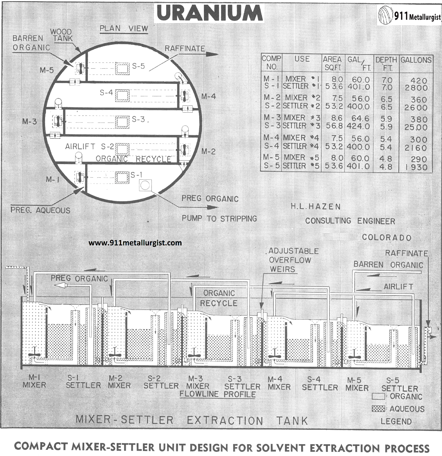
The flow from the mixer process passes to the settling process where the lighter kerosene containing the organic solvent and uranium rises to the top and the heavier aqueous settles to the bottom. Usually five stages of mixing and settling are used to effect maximum extraction of uranium and a compact mixer-settler unit has many cost-reducing advantages.
PART 1: Radium, Uranium & Vanadium Extraction & Recovery from Carnotite
PART 2: URANIUM, RADIUM & VANADIUM Ore Processing
PART 3: VANADIUM & URANIUM Extraction and Recovery
PART 4: RADIUM Extraction & Recovery
Design a Uranium Solvent Extraction Circuit
In 1956, Kerr McGee Oil Industries, one of the pioneers in the development and the commercial application of the solvent extraction process in uranium, designed a continuous solvent extraction circuit similar to the one illustrated in this design study. It accomplished the following:
- Combined mixers and settlers in a large common tank which minimized floor space and greatly reduced cost compared to a system using individual tanks.
- Eliminated expensive acid resistant piping and valves that would be required between individual tank units.
- Utilized an inexpensive wood tank. Water was circulated within the tank staves in order to prevent the wood staves from drying out due to the action of the kerosene.
All of the equipment used in the solvent extraction process for uranium must be acid proof to withstand the corrosive nature of the 1.0 pH pregnant aqueous solution used in the process. The presence of kerosene used as the solvent carrier eliminates the possible use of rubber or neoprene in the design of equipment. Normally, for mechanisms and hardware, stainless steel 316 has been found satisfactory, except where chlorides are present in the solutions. With the presence of chlorides, polyvinyl chloride has been found to be satisfactory. Wood tanks with wood mixer and settler partitions have worked very well and involve comparatively little expense.

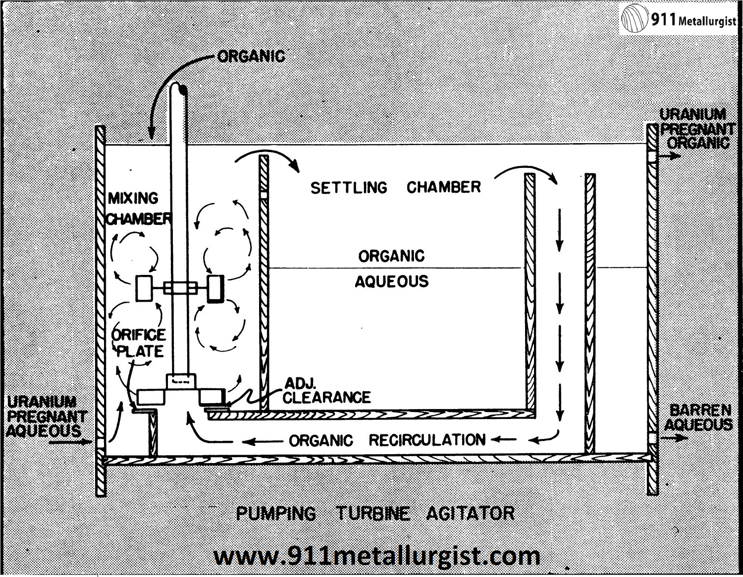
PUMPING TURBINE AGITATOR
Since the Kerr McGee installation, similarly designed systems have been installed at the Gunnison Mining Company, Fremont Minerals, Inc., and Mines Development, Inc., uranium concentrators. Minor modifications have been made in the various installations. However, probably the most significant change in the basic design was the method for the organic recirculation as illustrated in this Design Study.
Flow of the aqueous through the system is by gravity. The organic is advanced through the circuit by means of an airlift or pumps. It is necessary to have a high ratio of the organic solvent to the aqueous within the mixing chamber for proper operation. The organic is recirculated from the settler compartment back to the mixer compartment. This is done by means of an inexpensive Pumping Turbine installed on the bottom of the Solvent Extraction Mixer shaft. An overflow weir is installed in the settler section to allow a portion of the organic in the settler to flow to the bottom of the mixer compartment where it is lifted by the pumping turbine and recirculated in the mixing compartment.
Gravity flow of the aqueous through the unit is controlled by weirs between each settler and mixer. There is a 6″ differential in elevation between the weirs in each preceding compartment. The flow of the lighter organic passes to the boot of an airlift where it is advanced to the next mixer compartment.
The interface level between the organic and aqueous phases in the settlers is controlled automatically by the position of the weirs between the settlers and mixers. A monometer effect, using the difference in gravity between the lighter weight organic and the heavier aqueous phases, prevents the organic from passing out to the tailings as it would never have sufficient weight to force the column of aqueous over the weir. On the same basis, should the aqueous level start to rise in the settler it causes a higher flow of aqueous over the weir and thereby maintains the proper level.
Source: This article is a reproduction of an excerpt of “In the Public Domain” documents held in 911Metallurgy Corp’s private library.
