Table of Contents
The stamp mill‘s battery evolved, no doubt, from the pestle and mortar was not introduced until a comparatively recent date. Beckmann states that mortars, mills, and sieves were used exclusively in Germany throughout the whole of the 15th century, and in France stamps were unknown as late as the year 1579. Brough has suggested that the origin of stamp mills was probably due to the manufacture of gunpowder. It seems certain that in 1340 a stamp mill, used in connection with this industry, existed in Augsburg, and that Conrad Harscher, of Nuremburg, owned one in 1435. They were first applied to the gold industry at the beginning of the 16th century, a doubtful record stating that they were introduced into Saxony by Count von Maltitz in 1505, whilst in 1519 the processes of wet-stamping and sifting were established in Joachimsthal by Paul Grommestetter, who had some time previously introduced them at Schneeberg. The improvements gradually spread through Germany, and detailed descriptions and drawings of the apparatus were given by Agricola in 1556, from which it appears that the earliest battery consisted of a single stamp, raised by means of two levers fixed to the axle of a wheel. Dry crushing was at first employed, but the great production of dust soon led to the use of water in the mortar. In some Hungarian mines, Bennett H. Brough saw some primitive stamps in use, resembling those drawn by Agricola, weighing only 100 lbs. each, and having their heads made in some cases of hard blocks of quartzite. At that time, in cases where the conditions of water supply were favourable, these stamps were able to treat with profit an ore containing as little as 2½ ozs. of gold to 50 tons of ore, and at Zell, in the Tyrol, they were able to treat a slaty material containing 1 oz. of gold to 50 tons of ore. Such economical work is seldom possible with the modern Californian stamp under the most favourable circumstances.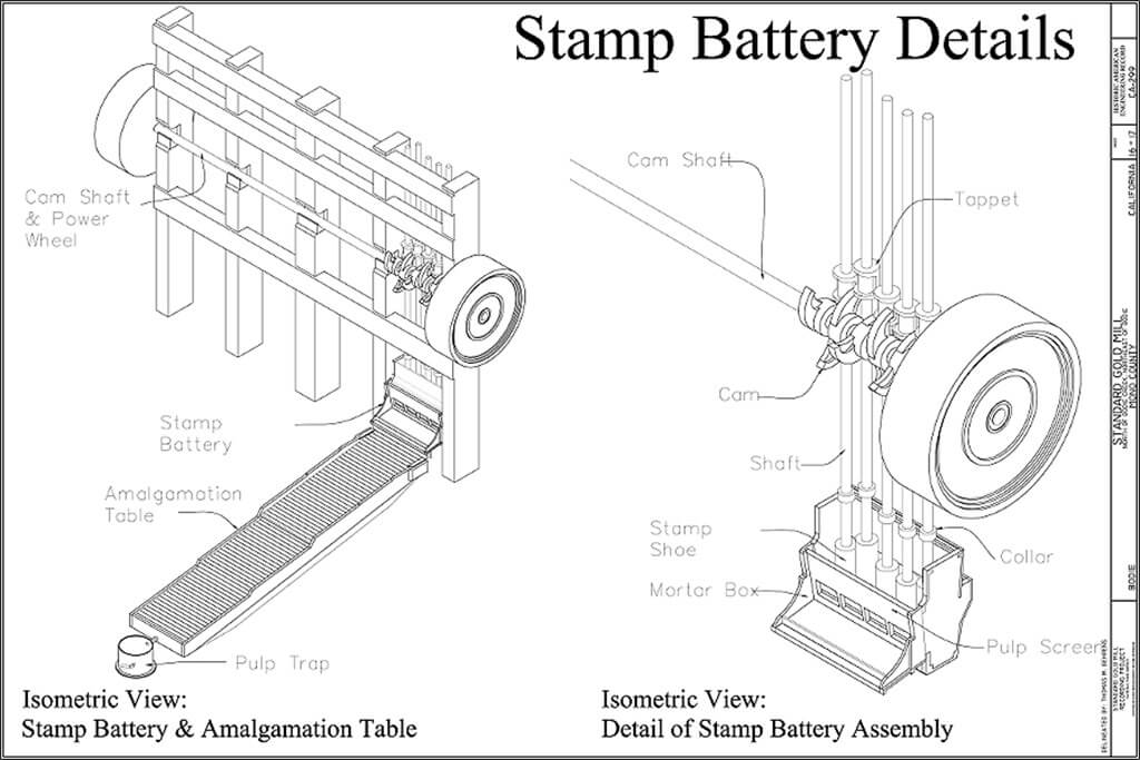
Agricola’s exact description of the treatment of auriferous quartz in Germany in 1556 shows that the methods in use at that time were strikingly similar to those still employed in Transylvania and the Tyrol, which were among the districts of which he wrote. Doubtless in these districts, the methods have been handed down from generation to generation with little change, while in other countries, where they were introduced hundreds of years later, the changes have been rapid and striking. In those points in which the older differed from the modern Tyrolean practice, it resembled the practice of the ancient Egyptians, so that the origin of the methods may, perhaps, be traced back to them. The wooden stamps, shod with hard stone or iron, were arranged in sets of three, and raised by cams to fall by gravity when released. The rock was shovelled dry into the mortar, and coarsely crushed by the blows of the stamps.
Next, it was ground as fine as flour in a stone mill supplied with water, and carried by the stream of water into the uppermost of three wooden tubs, whence it overflowed in succession into the other two. Revolving mechanical stirrers, furnished with six paddles, kept in agitation the contents of the tubs and “ separated even very minute flakes of gold from the crushed ore. These flakes, settling to the bottom, are drawn to itself and cleansed by the quicksilver (lying in the tubs), but the water carries off the dross.”Agricola here expounds the theory of amalgamation still adhered to in Austria, where mercury is regarded merely as a useful means of collecting particles of gold, which have already been separated from the crushed ore by their great density. The Tyrolean bowls, still in use at Vorospatak in Hungary and in a few retired valleys in the Eastern Alps, do not differ essentially from the tubs drawn and described by Agricola ; and, although wet crushing by the stamps has been introduced, the mortar is even now seldom furnished with screens in these mills.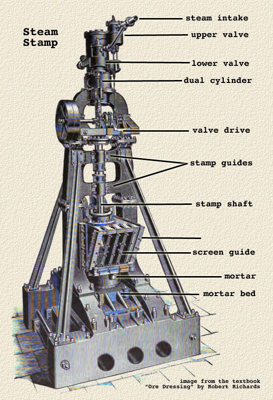
Elsewhere the changes in stamp battery practice, introduced since Agricola wrote his treatise, have been many and great. One of the first was the insertion of screens in the side of the mortar, so that two operations of crushing and sifting were united. In 1767 M. Jars saw these in use in the Hartz, though even then only a single screen of brass wire 12 inches square delivered the product of three stamps, and in several other districts in Germany screens had not been adopted. The screen was completely protected from the splash of the stamps, so that the sieving of the ore was very slowly effected by a current of water flowing through.
The most important improvement, however, has undoubtedly consisted in combining the operations of crushing and amalgamation by charging mercury with the ore into the battery, and placing amalgamated copper plates in the mortar, so as to catch gold. No mention of these practices appear to have been placed on record before stamp batteries began to work in California in 1850, although they had possibly been adopted in Georgia before that time.
The use of the copper plate was probably suggested by the experience in Mexico and South America of the working of the Cazo process, in which it was well known that amalgam tended to adhere to the copper sides of the vessel unless the proportion of mercury to gold and silver present was less than 4 to 1. Thus Baron Born wrote in 1786,—”In new kettles the inside becomes wholly and so perfectly silvered that it never can be cleaned. The silvery coat is daily increased by slow and gradual apposition, and the crusts of amalgama, accumulating on the bottom and sides of the vessels, become gradually so thick that on emptying them they often fall off by their own weight as silver plates, which, when dry, show the laminated texture of their daily augmentation.”
The knowledge of this behaviour of amalgam in the Cazo process must have been common to many who were engaged in exploiting the quartz veins of the West soon after their discovery, and the speedy application of this knowledge is exactly what might be expected from those quick-witted pioneers. Nevertheless, the exact date and locality of the introduction of the copper plate remains a matter for conjecture.
The copper plates fixed in the battery in the early fifties were about 4 inches wide and as long as the mortar, and were placed one on the “feed” side and one on the discharge side just underneath the screens. It was soon found that the plates worked better from the start if they were coated with mercury before they were placed in position, and this has now been invariably done for the last half century. Crushed ore, stones, water, and amalgam are flung violently against the plates, and the amalgam is retained in great part.
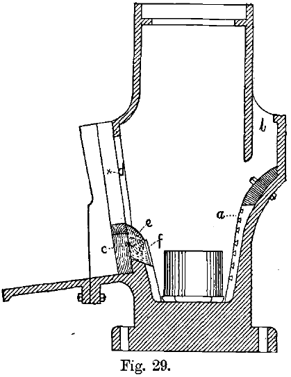
The scouring action of the pulp on the plates is, however, always great, and becomes more violent in proportion as the stamps are larger. The plate on the feed side, long ago condemned by many, is accordingly being discarded more and more, and that below the screens is curved away in such a manner that it cannot be struck directly by the splash from the stamp (see Fig. 29). A more recent step in this direction was to line the mortar with cast-steel plates, furnished with slots for the purpose of catching amalgam (see Fig. 29).
The tendency is now towards the discontinuance of inside amalgamation, and the abolition of gold-catching plates in the mortar. The introduction of coarser crushing in the battery, followed by re-grinding, has, of course, assisted this movement.
After leaving the mortar, the pulp was treated fifty years ago, in districts other than Transylvania, mainly by passing it over inclined tables covered with blankets, much in the same way as Jason may have seen the golden sands worked in Asia Minor. The sands accumulating on the blankets were washed off at intervals and ground in mills with mercury. In addition, the ore was frequently passed over or through baths of mercury, in imitation of the old Tyrolean practice, still adhered to, with modifications, in many Australian mills.
Amalgamated copper plates over which the pulp flowed were tried, after those placed in the mortars had been proved to be beneficial, but in Western America were at first almost everywhere rejected, probably owing to the great depth of the stream of ore and water made to flow over them. When long afterwards, about the year 1870, this mistake began to be rectified, the value of the plates was soon recognised in California.
The pulp is now led over the surface of these inclined plates in a very thin stream, not more than a quarter of an inch deep. The pulp does not run down in a regular stream, but in a series of little wavelets which tumble over and over, and are supposed to bring every part of the pulp successively in contact with the amalgamated surface. The catching powers of the plates are thus supposed to be practically independent of the tendency of the particles of gold or amalgam to sink to the bottom of the stream. This theory is not accepted by the Austrian school (see above, p. 98), and it is certain that native gold is caught more easily in proportion as it contains less silver (and is of higher density), so that when the particles of metal consist of an alloy containing a large proportion of silver, and are, therefore, of comparatively low density, the yield on the plates is generally poor. In any case, however, whatever be the working hypothesis adopted, the amalgamated plate should theoretically be better adapted for its work than the Tyrolean mill and other machines using mercury baths, owing to the slight depth of the pulp on the plates, and the short distance through which the gold particles are compelled to settle before reaching a catching surface. The plates are wiped down with rubber or brushes about once a day, and the gold separated in the usual way from the excess amalgam thus collected.
The German stamp has a rectangular stem made of wood or, latterly, of iron, with an iron head, the total weight never exceeding 300 to 400 lbs. It was introduced almost unchanged into France, Cornwall, and, after the discovery of gold in 1849, into the United States, but has given place in all new districts to the Californian stamp, and need not be fully described here. In 1850, the first stamp mill seen in California was erected at Boston Ravine, Grass Valley. The stamps consisted of tree- trunks shod with iron, and the framework was constructed of logs.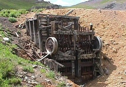
The ordinary method of reduction and amalgamation of gold quartz in a stamp battery now consists of the following operations:
- The ore is broken down to a moderate size, usually to about 2-inch cubes, by passing through the jaws of a rock-breaker, or by hand hammers.
- The ore is then fed into the mortar-box of a stamp mill, where it is pulverised to the required degree of fineness. In wet crushing, a stream of water is introduced also, and the blows of the stamps splash the water and pulp against screens set in the side of the mortar, the finely-divided ore being ejected in this way. In some cases the mortar-box is partly lined with amalgamated copper plates, by which some of the gold is caught and retained, mercury being in this case usually fed into the mortar-box with the ore and water.
- On issuing from the battery, the pulp is allowed to run over a series of inclined, amalgamated, copper plates, by which a further percentage of the gold is amalgamated and retained.
- The tailings are sometimes further treated by running over rough hides or blankets, by which some particles of gold and pyrites are retained, or the pyrites is separated from the valueless sands by concentration on some form of vanner or jig. These concentrates are subjected to further treatment, usually either by cyaniding, smelting, or chlorination. In other cases the tailings are separated, by settling in water and decantation, into “sands” and “slimes,” which are cyanided without previous concentration.
- At intervals the gold amalgam is wiped off the copper plates, the excess of mercury separated by squeezing through filter bags of chamois leather, buckskin, or canvas, and the solid amalgam thus obtained is retorted so as to distil off the mercury, and the gold is then melted.
The following is a general description of the machinery employed in stamp-battery practice:
The Stamp Battery
Californian “ gravitation ” stamps are in general use at the present day for crushing gold ores. A stamp is a heavy iron, or iron and steel, pestle, raised by a cam keyed on to a horizontal revolving shaft, and let fall by its own weight. Stamps are ranged in line in groups of five stamps each, which have a mortar-box in common. Fig. 25 represents the side view, and Fig. 26 the front view, of a ten-stamp battery, with the amalgamating tables removed to show the foundation timbers or mortar-blocks, A.
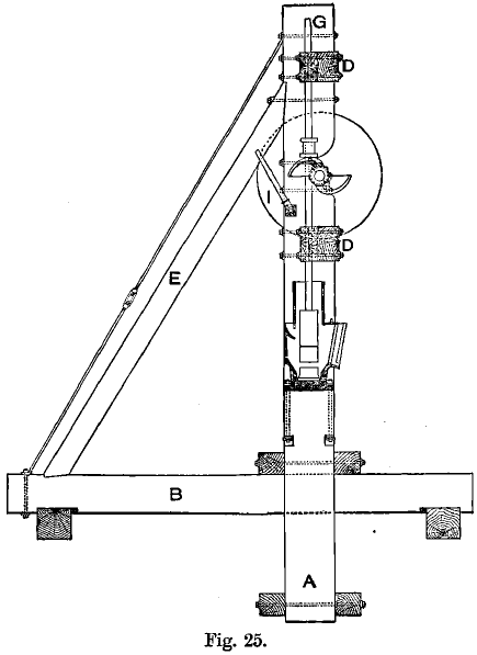
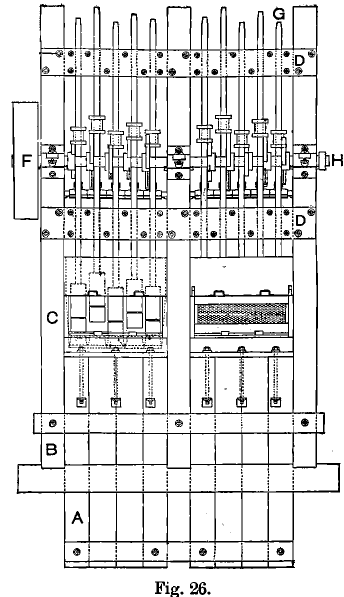
The foundations are of the highest importance, as, if they are badly made through carelessness or false economy, the efficiency of the battery is greatly decreased, and it soon shakes itself to pieces. The blow of a stamp is partly employed in crushing the ore, and is partly expended in producing a concussion or jar acting on the framework and foundations. The amount of energy used up in the latter way depends largely on construction. In preparing the ground for the foundations, the earth is removed until bed-rock is reached if possible, and the latter is then carefully smoothed and covered with a layer of concrete. The wooden mortar-blocks of from 6 to 18 feet long are placed upright in this trench, and the space round filled up with sand, or, as in the Transvaal, solid masonry is built round the blocks. Concrete mortar blocks are now often used instead of wooden ones. Heavy iron anvils or mortar blocks are also used on concrete foundations. The framework is made of wood, iron, or steel. It consists of the massive cross sills, B, on which rest the battery- or king-posts, C, and the braces, E. The posts are held together by the guide- or tie-timbers, D. The mud-sills are shown below the cross-sills. Frames of a number of different designs are in use.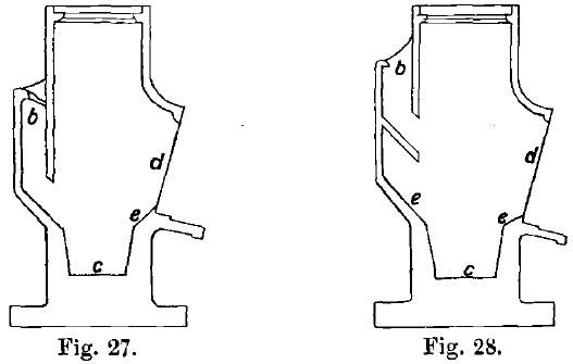
Stamp Mill Mortar Box
The mortars are made of cast iron, but differ in shape according to the nature of the ore and the corresponding modifications made in the course of treatment. They weigh from 1½ to 4 tons, being especially thick at the bottom where there is the greatest strain. An ordinary mortar is about 4 feet 7 inches long, 50 inches high, and 12 inches wide on the inside at the level at which the dies are set. The bottom is from 3 to 11 inches in thickness, and has a heavy flange cast on it, by which it is bolted to the mortar-blocks. These are tarred over, all cracks in them having been filled with sulphur, and are then covered with three thicknesses of blanket, carefully coated with tar on both sides. The mortar is placed on these blankets and securely bolted down. This arrangement lessens the chance of the mortar working loose, the jar being diminished. A sheet of rubber, ¼ inch thick, may be used instead of the blankets. Figs. 27 and 28 represent sectional elevations of the two chief types of mortars, Fig. 27 showing a mortar intended to be supplied with an inside amalgamated copper lining plate, e, on the screen side only, and Fig. 28 a mortar designed to have copper plates, e, e, placed both at the front and back. In both figures, b is the feed-opening through which the ore is introduced into the mortar; c is the bed on which the die is placed; d is the screen- opening. The chief difference between them is in the feeding arrangement; in the latter case the back plate is put in a recess, and is protected from the falling rock fed into the battery. Back plates are now not often used. The plates catch the coarse gold inside the mortar when the pulp is flung against them.
Cast-iron or steel lining plates and false bottoms take up the wear inside the mortar and are renewed when worn out. They last a few months.
A section of the mortar used at the Croesus mill, in the Transvaal, is shown in Fig. 29. a is a cast-steel lining plate with slots or recesses in it for collecting the amalgam ; b is the feed opening; c the wooden blocks for carrying e, the copper plate ; d is the screen opening; and f a steel plate.
The width of the mortar varies from 10 to 14 inches at the level of the bottom of the screens. As has been already mentioned, narrow mortars are best fitted for rapid discharge, but, if hard flinty ores are to be crushed, a narrow mortar causes frequent breakage of the screens, unless the discharge is deep—i.e., unless the bottom of the screens is a considerable distance above the surface of the dies. By this latter arrangement the output is reduced, since, the nearer the screens are to the dies, the more rapid is the discharge. The depth of the discharge is the distance, measured vertically, from the top of the die to the bottom of the screen. It varies from zero to about 7 inches in modern mills. Adjustable battery-screens keep this depth constant, in spite of the wearing of the dies. The screen-frame is supported on a wooden chuck-block, which is easily removable, and to which the copper plate is bolted. When the dies wear down, the chuck-block is replaced by one of less height, to which a suitable plate has already been fixed.
The splash-box, not shown in the figures, and now often omitted, is bolted to the outside of the mortar just below the screens. It is rectangular, consists of wood or iron, and is of the same length as the mortar. It receives the pulp as it passes through the screens, and distributes it evenly over the amalgamating tables by a number of spouts, usually three. Instead of the splash-box, a splash-board or a canvas shield is now almost universally employed. The lip of the mortar projects some inches, as shown in Fig. 29, and to it is bolted a cast-iron apron about 14 inches long, which often carries an amalgamated copper plate, the apron-plate. The pulp is dashed through the screen against the splash-board and falls thence on the apron-plate, which is often provided with a curved lip to prevent the splashes from reaching the amalgamated tables. The old form of mortar had its upper part, or housing, of wood, but, as mercury is lost through the smallest aperture, and it was difficult to make these wooden housings quite tight, mortars are now cast in one piece, including the housings. The roof of the mortar is made of 2-inch planking, through which holes are cut to admit the stems of the stamps and the water pipes.
When the mortar is in place, the dies are put into it, a layer of sand being often introduced first. The dies consist of two parts, the footplate or base and the die proper or body.
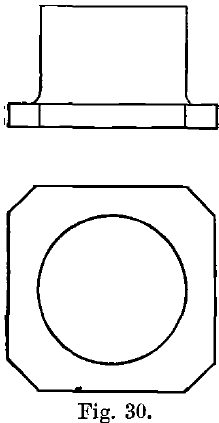
Fig. 30 shows, in plan and elevation, one of the many forms of dies in use ; here the base is almost square, so as to fit the mortar ; it is 1 or 2 inches thick, and 9½ to 10 inches square. The body is cylindrical, 5 or 6 inches high, and of the same diameter as the shoe. Shoes and dies are now generally made of forged steel, the dies being kept a little softer than the shoes. They last longer than the iron shoes and dies formerly in use. Chrome steel and manganese steel have also been used for shoes and dies. Sometimes steel shoes and iron dies are used. The wear of iron shoes and dies was formerly stated to be about 2 or 3 lbs. per ton of ore crushed in California. At the Robinson Mine, South Africa, the wear of steel shoes and dies is, according to Harland, 0.45 lb. per ton crushed for shoes and 0.30 lb. per ton for dies. According to I. Roskelley a 12-inch steel shoe weighing 225 lbs. is worn out on the Rand in about ninety days, during which from 450 to 500 tons of ore are crushed. The shoe is used until it is worn down close to the shank, and weighs only 35 or 40 lbs. when discarded. Forged steel dies, with cylindrical bodies 6 inches high and weighing 120 lbs., last as long as the shoes, and weigh only about 40 lbs. when thrown out, if they have worn down evenly. These rates of wear correspond for shoes to about 0.40 lb., and for dies to about 0.17 lb. per ton of ore crushed. When the body is worn down to within from ½ inch to 1 inch of the base, the die is replaced. Dies wear more slowly than shoes since they are protected by a layer of pulp, which is over an inch thick. The dies are all renewed together, as it is important that those in the same battery should be of equal height, otherwise one or more will become almost bare of ore, and a disastrous pounding result. If a die breaks, it is not replaced by a new one, but by one worn to the same extent as the others in the battery. Iron false-bottoms or chuck-blocks or sand packings are placed beneath partially-worn dies, so as to keep the depth of the discharge constant.
Dies require to be hardened and tempered very evenly, according to Roskelley, to prevent uneven wear. A die worn down at one side causes a diminution of output, and may result in a broken stem. According to E. E. Aulsebrook, the three centre dies in a mortar wear down at the back faster than at the front, on account of the size of the material which is fed at the back being larger than that which is crushed at the front. For this reason he recommends dies to be turned round once a month. He also states that dies often wear unevenly because the stamps are out of centre.
The cam-shaft, H, Fig. 26, is of wrought iron or steel, and about 6 inches in diameter. It is now usual to have a separate cam-shaft for each five or ten stamps, which have thus a separate driving pulley. The advantage of this arrangement is that repairs can be done to one or more stamps without necessitating the stoppage of the whole mill, as used to be the case when there was only one cam-shaft. The cam-shaft is placed at a distance of from 5 to 10 inches from the stem-centre, and is 9 to 10 feet above the mortar bed. The bearings rest on supports attached to the battery posts, generally on the discharge side.
The cams are made of cast steel. The double cam, views or which are shown in Figs. 31 and 32, is now in almost universal use, though single and treble forms have been employed. Sometimes cams are cast in two pieces which are bolted together, so that when one is worn out, it can be replaced without first removing the other cams on the shaft, but these sectional cams work loose, and are not much used. Cams are either right or left handed. Both are used in the same battery to equalise the cam-thrust, the stamps being rotated in opposite directions. The shape of the cam face is the involute of a circle slightly modified at the end so as to stop the upward motion gradually. The radius of this circle is equal to the distance between the centres of the cam-shaft and the stem, which depends on the height to which the stamp is to be lifted, so that the curve of the cam varies with the drop; A cam should last several years unless broken through being a faulty casting, or through carelessness in letting the stamp fall when hung up.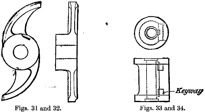
The old-fashioned keyed cam has now been replaced generally by the Blanton cam, which will take any position on the cam- shaft. To secure it, two holes are bored in the cam-shaft, and two pins dropping into these hold fast a semi-circular tapering wedge or “bushing.” The cam slips over the bushing and tightens itself in working. When it is necessary to take off a cam, a slight blow on the back edge with a hammer loosens it instantly. The “new” Blanton cam is said to be found still more convenient than the older form. The bushings are abolished, and the cam-shaft made with ten taper faces, so that its cross-section is like a ratchet-wheel with ten teeth instead of being circular. The bore of the cam has ten corresponding faces, and the cam slips on in any one of ten positions. It is then tightened sufficiently to hold it in position until put into operation, when it tightens itself further on the shaft in proportion to the work it has to do.
The cam-face works against the collar or tappet, shown in plan and section in Figs. 33 and 34, which is bored out to fit the stem of the stamp. The tappet is usually made of hard fine-grained cast steel, and is fitted with a wrought-iron gib, which is pressed against the stem by two or three keys behind it, thus binding the tappet firmly on the stem while, at the same time, admitting of rapid adjustment to another position. Adjustment of the tappet on the stamp-stem is required every few days to allow for the wear of the shoes and dies. The entire end surface of the tappet comes in contact with the cam-face, by which the stamp is raised and, at the same time, rotated, all its parts being round. The effect of this is, that the shoe does not strike the ore in the mortar in exactly the same place twice in succession, and the wear of its face is made more uniform. The greater part of the revolution takes place during the raising of the stamp, but the latter does not quite cease to rotate as it falls, and a slight grinding action on the ore has been noticed by many observers. The amount of rotation varies with the fall, the extent to which the cam and tappet are greased, and the state of wear of their surfaces. A little grease is always added to reduce wear, but, if too much is present, the stamp does not revolve at all, while, according to J. H. Hammond, when the tappet is in the right condition, one revolution is effected in from four to eight blows, with a 6- or 8-inch drop. Other observers find the usual rate of rotation more rapid, and in Gilpin Co., Colorado, where the average drop is from 16 to 18 inches, the stamp makes from 1¼ to 1½ revolutions at each blow, according to Rickard. Tappets last for four or five years ; and, having both ends alike, they can be reversed when one end is worn out, and their worn and grooved faces can be planed down when necessary. Some millman assert that tappets may be broken by the cam if keyed too tightly to the stem.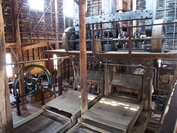
As the cam-thrust is not applied at the centre of the stamp, there is always a considerable side pressure, which greatly increases the friction in the guides and wears the latter out, besides causing a loss of power. Moreover, another result of this is that the stamp tends to be inclined (not vertical) when it is released, and so the blow on the die is given slightly to one side—i.e., the side of the die on which the cam works. Consequently, there is a tendency for this side to wear down more quickly than the other. To obviate these disadvantages, cams have been introduced at Johannesburg with a wide hub, and the two blades set one at each end of the hub, so that they work on opposite sides of the stamp and cause it to revolve in different directions at each successive uplift. The Blanton cam, now generally used on the Rand, is fastened to the shaft by a semi-circular wedge pinned to the cam-shaft, no keys being necessary.
The pulley on the cam-shaft (F, Fig. 26) is made of wood on cast-iron flanges ; if iron alone were used, the rapid succession of jars, caused by the dropping of the stamps, would soon cause the material to crystallise and break. A tightener pulley on the belt driving the cam-shaft is often used, by which the stamps can be put in motion or stopped without interfering with the driving power.
The stamp itself consists of three parts, the stem, the head or boss, and the shoe. The stem (G, Fig. 26) is from 12 to 16 feet long, and from 3 to 3½ inches in diameter; it is made of wrought iron or steel, or steel in the middle portion with wrought-iron ends, and has both ends tapered for a length of 6 or 8 inches to fit the heads, so that, if one end is broken off, the stem can be inverted and the other end used. The head and shoe are made of equal diameter—viz., about 8 or 9 inches. The head is of hard fine-grained cast steel, about 15 to 24 inches long, and has a tapered socket at each end, the upper one for the stem and the lower for the tapered shank of the shoe. When these are driven into their respective sockets, into which a few strips of wood are inserted to keep the two metal surfaces from touching each other, a few blows by the stamp bind them securely together, no other fastening being necessary. Slots are provided at the base of the two sockets, through which wedges may be driven to force out the shoe or stem when necessary. Roskelley advocates a hole about 2½ inches in diameter drilled through the axis of the head to facilitate the removal of broken stems. The head lasts several years, being rarely ruptured. The shoe consists of two parts, the shank, which fits into the head, and the shoe proper or butt. It is made of hard forged steel, with the shank made softer than the butt in the tempering. The diameter of the shank is about half that of the butt. The shoe is replaced when the butt, which is from 9 to 12 inches in length when new, has been worn down to about 1 inch in length. To keep the total weight of the stamp constant, several sizes of heads are sometimes used in one mill, the heavier heads taking partly-worn shoes. “Chuck-shoes” are inserted between heads and shoes with the same object. Shoes last about three months on the Rand, according to Roskelley.
The relative weights of tappet, stem, head and shoe, which together make up the stamp, vary considerably. There is an advantage in increasing the weight of the stem, as one of small diameter tends to spring and bend from the blow of the cam, or when the stamp falls, and to wear the guides rapidly. The stem weighs from 250 to 600 lbs., the tappet from 80 to 150 lbs., the head from 175 to 370 lbs., and the shoe from 100 to 250 lbs. The total weight of the stamp is usually from 650 to 1,350 lbs., but is sometimes as low as 450 lbs., and, for prospecting purposes, the weight is only from 100 to 300 lbs.
The stamp stems are guided in boxes bolted to the wooden guide-timbers, which also serve to hold the battery posts together. There are two of these guide-timbers (D, Fig. 26), one within 2 or 3 feet of the top of the battery posts, and the other about 6 or 7 feet lower. The depth of each guide is about 15 inches, and the stems are fitted closely to the guides, metal boxes being used occasionally, although wood is much more general. The guide-beams are sometimes pierced with large square holes in which bushes of wood, with the grain parallel to the length of the stamp, are placed fitting the stem exactly. In this way, the guide-beams themselves are preserved from wearing out. Sectional guides, consisting of a series of iron keys enclosing wooden bushings, are also used. In this case each stem has a guide to itself and the bushings can be renewed by hanging- up the one stamp without stopping the other stamps in the battery.
Each stamp is provided with a finger or jack (I, Fig. 25) made of wrought iron, or wood protected by iron. The jack is for the purpose of raising the stamp and hanging it up out of reach of the cam. When this is to be done, a strip of wood, an inch or more thick, is laid with one hand on the cam as it rises, and the stamp is thus raised an inch higher than usual, so that the jack can be slipped in under the tappet with the other hand. The stamp is thus suspended above the cam and can be repaired without stopping the others, while it can only be released in a manner similar to that in which it was hung up. Above the stamps there is a double rail, on which is a tackle block carriage ; by this the stamps, can be lifted up for repairs. When the stamps are to be set up, the head is put on the die and the stem dropped into it, canvas or other packing being usually put into the head socket and the stem dropped into that. The stamp is then raised and dropped into the shoe, the shank of which is surrounded by strips of wood for packing. As already stated, the parts are soon wedged firmly together by raising and letting fall the stamp a few times.
The height of the “drop” of the stamps varies from 4 to 18 inches, and the number of drops per minute varies from 30 to over 100. These depend on one another to a great extent, an increase in the height of the drop being necessarily accompanied by a diminution in the number of drops per minute. With a drop of inches, about 95 blows can be obtained, the tappet then just having time to fall after leaving one face of the cam, before the other begins to raise it. As, within certain limits and under certain conditions, an increase of speed results in an increase of yield of pulverised ore, efforts have been made to raise the number of blows per minute. The subject will be returned to when the conditions for successful amalgamation are discussed.
D. B. Morison discusses the question of height of drop from the point of view of speed of crushing in a valuable paper, which should be consulted. The time occupied in seconds in the fall of the stamp, if all friction, including the resistance of the air, is left out of account is √2H/G, where H = height in feet, and G = 32.3. For a fall of 8 inches this amounts to about 0.2 second, but owing to the friction between the stamp and the guides and the resistance due to the water, the actual time taken, according to Morison’s experiments, is about 0.225 second (see Fig. 35). The velocity at the time of impact and the force of the blow are correspondingly diminished, the latter being 17 per cent, less than it would be if the work were done without friction in vacuo, a mean result of twenty-four experiments. The time required in raising the stamp is somewhat greater, owing to the imperfect method necessarily employed. The shape of the cam causes the stamp to start upwards at a certain velocity immediately the cam meets the tappet, and to maintain the same velocity until near the end of the stroke. In a properly constructed cam, designed to give a drop of 8 inches, the vertical component of the velocity of the cam, is for ninety drops per minute, about 2.5 feet per second. If the cam were suddenly removed from the tappet when moving at this velocity, the stamp would continue to rise against gravity for about 1 1/6 inch, neglecting friction.
The inherent defect of the cam is that it strikes the tappet a tremendous blow in the effort to lift the stamp at the full velocity from the start, and it is this blow which is the cause of much of the intense noise and vibration felt in every stamp mill. In spite of the power of the blow, which tries the cam-shaft severely, the dotted curve in Fig. 35 shows that at first the movement of the cam is checked a little, probably in part by distortion of the cam, and that it rapidly recovers itself, and by elastic distortion in the opposite direction lifts the stamp faster than the normal rate, and these alterations succeed each other during the whole lift, after which the cam presumably recovers itself in the time that elapses before it strikes the next blow.
Fig. 35 shows a curve traced out by a pencil attached to a 900-lb. Sandycroft stamp, the ordinates representing vertical movement of the stamp and the abscissae being time in tenths of a second. The figure was traced out during one of a number of experiments made by Morison, who subsequently devised the high-speed stamp described in Chapter viii.
Stamp Mill Screens
The screens are set in iron frames, which now usually slide in grooves cast in the mortar, and are keyed to it, but were formerly fitted into recesses and bolted. They are made either of steel or brass wire-cloth, or of Russia sheet-iron or steel, or tin-plate, in which holes are punched. The holes are round, or consist of long slots (from ¼ to ½ inch long) ranged parallel or inclined to each other. The shortest diameter of these holes ranges from about 1/80 to 1/12 inch or more, according to the nature of the ore and the method employed in its treatment ; the usual size is from about 1/24 to 1/40 inch. The relative advantages of wire-cloth and sheet-iron are not yet beyond dispute, and vary with the nature of the ore. Slots appear to be better suited for discharge than meshes, but, on the other hand, there is a great loss of discharge area in the use of punched iron. Thus a wire mesh screen, containing 18 holes to the linear inch, has 324 holes to the square inch, while a round-punched sheet-iron screen has only 140 holes of the same size per square inch.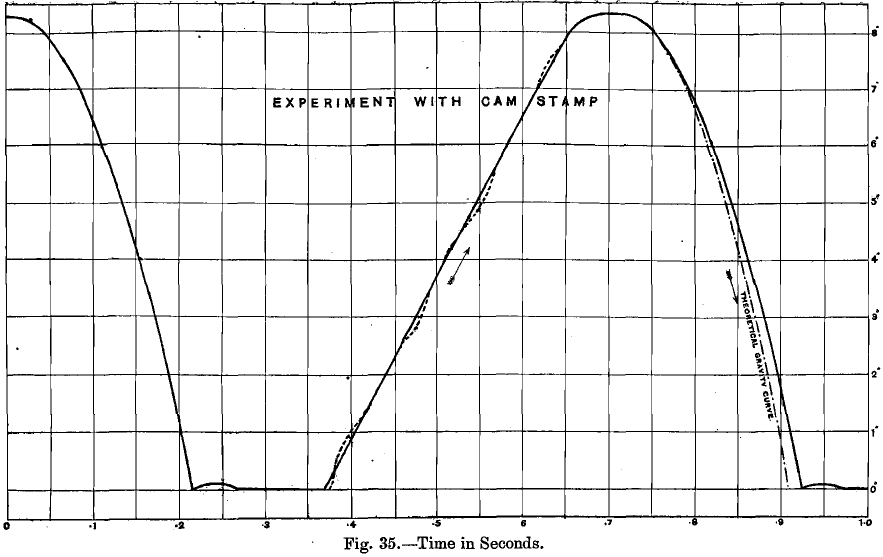
Although sheet-iron is the material usually employed for screens, it is often preferable to use copper, as pyritic ores, if kept for any length of time after being mined, soon become oxidised and acidified, and the ferrous sulphate thus formed corrodes iron rapidly, whilst the water used is often more or less acid if it comes from mines. Copper is not attacked in the same way. T. A. Rickard has shown that the life of screens in the mills at Blackhawk, Colorado, diminishes as the creek is descended, the water becoming more and more impure. At the South Clunes United Mill, Victoria, iron punched gratings lasted less than a week, but, on introducing copper plates containing 100 holes per square inch, the life of the screen was increased to a month, and 275 tons of ore were passed through it. At Blackhawk, the iron screens last while from 80 to 430 tons are passed through them, according to the position of the mill. At Grass Valley, the average is 200 tons, at Bendigo, 134 tons, and at Otago, N.Z., only 40 tons. In California the brass-wire screens last from 10 to 14 days, corresponding to a passage of 120 to 140 tons, and the Russia-plate lasts from 15 to 40 days, the average being 30 days, corresponding to the passage of about 330 tons. The rate of wear of the screens depends greatly on their position, being more rapid with a shallow than a deep discharge, and more rapid in a narrow than a wide mortar. Pieces of iron or wood in the ore may cause the screen to break, and these should, consequently, be removed from the ore as far as possible. The battery is hung up now and then, so that a thorough inspection of all the screens may be made, and those that are broken replaced.
The screens were formerly set vertical, but they are now placed at an angle which varies somewhat but is never far from 10°, and this has been found to facilitate discharge. In wet stamping, screens are usually placed on one side of the mortar only—viz., that opposite the feeding side. In cases where the discharge is required to be as rapid as possible, the screen area is increased, and double discharge (front and back) mortars have been made, but have not been used much, except for dry crushing, and screens at the ends of the mortars are used at Harriettville, Victoria (Rickard). The area of the screen is usually from 3 to 4 square feet per battery, the height from the bottom to the top of the screen being from 8 to 10 inches. On the Rand, the screen openings are usually 52 inches long and 10 inches deep. According to H. T. Pitt the output is increased by about 5 per cent, by making the screens 22 inches deep instead of 10 inches. Opinions differ as to the necessary amount of screen area to be used. It has been contended that the capacity of a battery is really limited, not by its crushing, but by its discharging power. Thus, by a number of experiments conducted some years ago at the Metacom Mill, California, it was shown that when crushed pulp instead of the unbroken ore was fed into the mortar, the rate of discharge was not increased. This was taken as a convincing proof that the discharge area is usually far too small, Nevertheless, double discharge is hardly ever used for wet- crushing mills, the various objections that are made to it being summarised as follows:
- Inconvenience is caused in the arrangement of the copper plates, both inside and outside the battery.
- So great a quantity of battery water must be used, that the pulp is too thin for efficient amalgamation on the plates.
- The ore does not stay long enough in the battery to be effectively amalgamated.
Stamp Fall Sequence
The order in which the stamps drop is of considerable importance. If they were let fall in succession from one end to the other of the mortar, the pulp would be driven before them, so that the stamp which fell last would have its die covered by too deep a cushion of ore, while that at the other end would be almost bare. The result to be obtained is to keep the ore equally distributed through the mortar, so that each stamp shall do the same amount of crushing, although it is inevitable that the middle stamps should be more efficient than the end ones in discharging the ore. The order most favoured in California is 1, 4, 2, 5, 3, and that on the Rand is 1, 3, 5, 2, 4, whilst the orders 1, 5, 2, 4, 3 and 1, 5, 3, 2, 4 are also often used. Several other orders have their advocates, and are probably little inferior to the above for the particular ores on which they are employed. Since the end stamps are of less efficiency than the others, it has been argued that a larger number of stamps in one mortar would be advantageous, and at Clausthal, in the Hartz Mountains, there are usually from nine to eleven stamps in a battery! placed close together, space being greatly economised in this way. Long and wide experience has, however, proved that the best number is five.
Stamp Mill Feeder
Ore is fed into the battery either by hand or by automatic machines. It is often asserted that really intelligent hand-feeding is better than the automatic method, since the stamps are not all equally efficient. The feeder on small mills is often expected to break down the big pieces of ore with a sledge hammer, a rock-breaker not being used, but this method of working may be safely set down as irrational and uneconomical, and the result usually is that large and small pieces go into the mortar together. 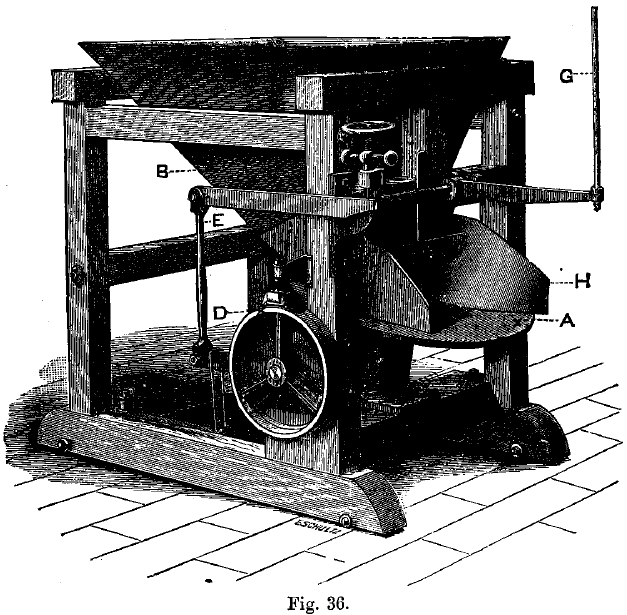 In the United States and in the Transvaal, self-feeders are almost universally employed in modern mills. The art of feeding consists in keeping the depth of pulp on the dies constant throughout the battery, as long as the work is carried on. This is much better done by automatic machinery than by hand, and it was found that by the introduction of the former in California the capacity of the stamps was increased by 15 to 20 per cent., while the wear of shoes and dies was decreased by 25 per cent., and that of the screens by 50 per cent. It is not difficult to discern the cause of the advantages, for, if the dies are insufficiently covered with ore, less crushing is done, while a greater concussion must be taken up by the stamp and by the die, mortar. If the die is quite bare this concussion is so great that the stem may be bent or broken, and the shoe and die battered. On the other hand, if the ore is too deep in the mortar, there is so thick a cushion that much of the force is taken up in compression without crushing it; whilst, besides the reduction of output, the head, under these circumstances, sometimes becomes detached from the stem, which is broken or battered by the next blow. The maximum capacity is obtained with “low feeding,” the depth of pulp on the dies being about 2 inches or less. One advantage of even feeding is that a larger proportion of gold is caught, owing to the more regular and even flow of the pulp over the plates, the danger of scouring being diminished.
There are many automatic feeders of different designs. Hendy’s Challenge feeder, shown in Fig. 36, is a typical machine, and is more widely used than the others. It is constructed so that the tray, A, below the sheet-iron hopper, B, is revolved in a horizontal plane by means of a gear-wheel placed below it. The ore is fed into the hopper and the amount passing to the tray, A, is regulated by a sliding door. The gear-wheel is set in motion by a friction grip, D, placed on the outside of the frame, and actuated through the lever, E, by the bumper-rod, G, against which the tappet of the stamp strikes. At each partial rotation a given quantity of ore is scraped off by the stationary wings or side plates, H, resting on the tray, A. This amount of ore is regulated by the condition of the mortar. The machine is especially adapted for very wet or sticky ores. In general one feeder is sufficient for a battery of five stamps, more ore being fed to the middle stamps, where the most work is done, than to the end ones. The feeders are sometimes suspended from above instead of being supported from below.
Adding Water to a Stamp Mill
The water is usually supplied to the stamps by horizontal pipes passing just above the top of the housing of the mortar-box, with one or two feed pipes to each battery. H. T. Pitt prefers five ½-inch holes along the back of the mortar box level with the feed chute, with the nozzles of the water pipes pointing so as to discharge the water against the dies from the back. In front of the battery there is sometimes another pipe of about half the size, to supply water to the tables to help carry off the pulp. The feed pipes are often pierced with pinholes, so that the water is supplied as a number of fine jets.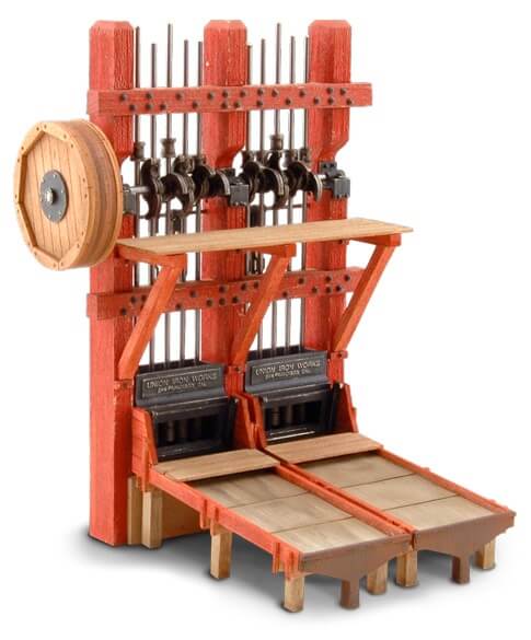
The amount of water used varies from 1¼ to 6½ gallons per stamp per minute, the average in California being about 2½ gallons, on the Rand about 5½ gallons, and in Colorado only about 1¾ gallons. In California, with fast-running rapid- discharge batteries, the amount of water per ton of rock crushed varies from 1,000 to 2,400 gallons, the mean being about 1,700 gallons, while in Colorado the average amount is as high as 2,500 gallons. On the Rand the amount of water per ton of rock is often put down as 10 tons or 2,000 gallons, but Roskelley gives 6 to 7½ tons for the Robinson Deep in experimental runs. Besides varying with the method of crushing adopted, the amount of water varies with the nature of the gangue, clayey ores requiring more, while the large quantity required by sulphide ores is due to the deep discharge necessitated by the difficulty of catching the gold, as well as to the high density of the pulverised material, which renders it more difficult to convey in suspension over the plates. As a rule, the more rapid the output, the less water per ton of ore is required in the battery. Coarse crushing requires less water in the battery, but, on the other hand, more has to be added on the plates. The amount of battery water per ton is increased by over 20 per cent, by the employment of double-discharge mortars. The amount of water to be added on the plates varies with their grade, as well as with the density and size of the particles of crushed ore. It should be only just enough to prevent the pulp from accumulating on the plates, as any excess over this tends to check amalgamation and to scour the plates. Richards gives the average amount of water used in 21 mills as 2.77 gallons per stamp per minute, or 6.68 tons of water per ton of ore crushed. The average duty of a miner’s inch in a gold stamp-mill is given by P. M. Randall as 12 tons of quartz if the head under which the water is supplied is 4 inches, and 15.88 tons if the head is 7 inches. This gives the proportion of the volume of water to that of ore as 11.1 to 1. This may be compared with the proportion of between 7 and 10 to 1 in Siberian placer working, and as much as 30, or even 50 to 1 in hydraulic mining. It may be mentioned that a ton of 2,000 lbs. of quartz occupies about 13 cubic feet when unbroken, and about 20 cubic feet after having been broken up, so that in a lode a cubic yard contains about 2 tons, and in tailings heap only about 1 1/3 tons.
Stamp Mill Sampling
It is usual to take samples of the pulp issuing from the screens, and also after it has passed over the amalgamated plates. The method adopted at some mills is to catch the whole stream falling from the lip of the mortar for a fraction of a second. This is done by a trough 6 inches wide applied by hand. Automatic sampling would be better.
Where to Build a Stamp Mill
This should be easily accessible by road, rail, and water, if possible moreover, it should be near both wood and water, and there should be a good fall of the ground. The least fall that is considered sufficient in California is 33 feet from the mouth of the rock-breaker to the floor on which the concentrators are placed, when rock-breakers are used, followed by stamps, copper tables, sluice plates, and two successive concentration tables. If a second concentrator is dispensed with, however, and space otherwise economised as far as possible, 29½ feet may be enough.
Stamp Mill Design
A typical general Stamp Mill Design and its machinery is shown in section in Fig. 37. This represents a mill in which the ore is delivered from the ore-cars through a grizzly on to the rock-breaker floor, and thence by a shoot to the automatic feeders of the stamp battery; the pulp, after passing over the plates, is conveyed by sluices to the double row of “frue vanners” (described in Chap, ix.), which are shown standing back to back on the lowest floor. Large bins for mixed ore as received from the mine are sometimes installed of sufficient capacity to hold several days’ supply for the stamps, in case of breakdowns or other delays in the mine. Their floors are made of planking, which is laid with the lengths in the direction of the slope, for, if placed transversely, the boards wear fast, and the ore packs at the edge of each one, with the result that its movement is impeded and must be assisted by shovelling. The slope should be at least 45° in order to enable the ore to move downwards by gravity, when the lowest portion is drawn from the shoot. Ore-bins with flat bottoms have greater capacity, but necessitate an additional handling of the ore. The sills of the bins should be placed horizontally on terraced ground, not on the slope of the hill. A shoot from the mixed ore-bin door leads to a grizzly, through which the fine ore drops into the main battery ore-bin. The larger pieces of rock are discharged either into a coarse ore-bin or else upon the platform by the side of the rock-breaker and on a level with its mouth, into which it is shovelled by hand. The former course is preferable, as in that case the rock-breaker can be fed continuously by a gate in the coarse ore-bin, which is opened and shut by a rack and pinion. By this arrangement there is a saving of labour, but the chief advantage is that the rock-breaker is thereby kept constantly at work. At the North Star Mill, California, it was found that when, by arranging for a continuous feed from the coarse ore-bin down a shoot leading direct to the rock-breaker, the latter was in constant work, it absorbed 12 horse-power, as against 8 horse-power when in intermittent work, but its output was over 50 per cent. more. When the stamp battery is used only to crush the ore, which is subsequently treated in pans or other amalgamators, or by concentration, it is of great advantage to separate the fine product of the rock-breaker by sieving, instead of passing the whole through the stamps. This arrangement increases the output and prevents unnecessary sliming of the ore, thus greatly reducing the loss of sulphides when an attempt is made to save these by concentration. It is becoming customary in large mills to place the rock-breakers in separate buildings.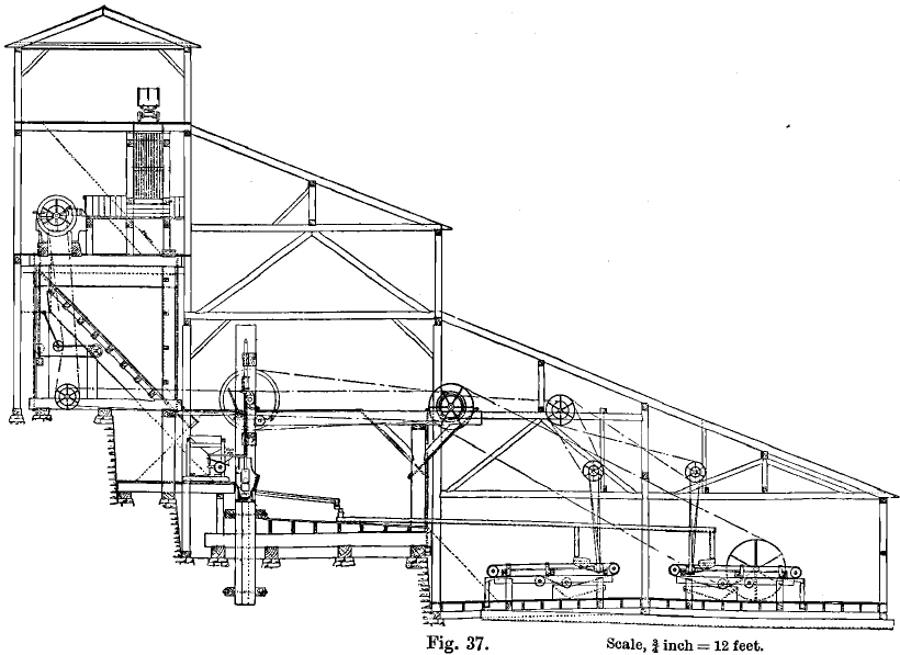
The product of the rock-breaker is mixed as thoroughly as possible with the ore, which originally passed through the grizzly, and led by means of a shoot direct to the automatic feeders, which should be mounted on wheels, so as to be readily movable. Plenty of space must be left behind the feeders for convenience in repairing and in the exercise of supervision. The amalgamating tables should also be easily accessible, space being left to pass between them, and the same remark applies to the sluices and the tables or other appliances for concentration. H. T. Pitt has suggested that the amalgamated tables should be separated from the battery by a space of several feet to allow space for sampling and for repairs. The pulp would then be delivered at the tables by launders. All shafts, bearings, &c., should also be easily accessible, so that oiling, relining, and repairs may be readily done. The battery house should be of ample size to allow space for handling cam-shafts, &c., when they are being replaced.
The tailings are discharged into a large sluice by which they are carried into a river, or into the sea, or run into settling pits, or impounded behind dams. One of the two latter courses is adopted, either if water is scarce, so that it is necessary to use it over again, or if the discharge of tailings is forbidden by law, or if the tailings are rich enough to be subjected to further treatment, at once or at some future time.
The whole of the machinery is contained in a strong building of timber or corrugated iron, to protect it and the workmen from the weather, and to prevent theft of amalgam. The interior should be lighted by as many windows as possible, in order to facilitate superintendence and repairs. In cold climates, the mill buildings are sometimes warmed by passing the flues from the boiler fires through them from end to end, before leading the products of combustion to the stack, or by steam pipes.
