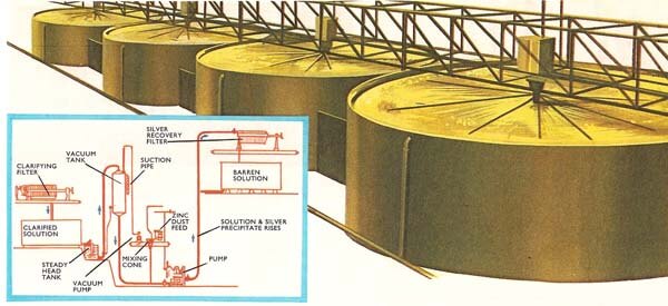
Producing a Silver Flotation concentrate from this EXAMPLE Argentite (cubic silver sulfide (Ag2S)) Flotation Circuit enters the first of four successive Argentite leach tanks. The purpose of this leach circuit is to dissolve the silver and gold recovered in the Flotation Circuit. A high strength solution of sodium cyanide, air, and lime are added to the first tank to provide the excess cyanide, oxygen, and protective alkalinity required for successful leaching. Dissolved precious metals are recovered in the small Argentite drum filter, the tails are sampled and fed to the tails box for disposal, and the pregnant solution is delivered to the primary filters vacuum receiver, where it is combined with the pregnant solution from the other filtration circuits. This section is intended to be read in conjunction with Flowsheet and Piping and Instrument Diagram.
The Argentite, this silver mineral, Leaching and Filtration Circuit is designed to the following criteria.
| Silver Leaching Retention Time | 96 hours |
| Cyanide Concentration | 10 gm/litre |
| Solids Concentration | 20% solids |
| Leaching pH | 10.5 |
| Ag Leach Residue Filtration Rate | 120 kg/m2/hour |
| Filter Wash Ratio | 1.5:1 |
Detailed Leaching and Filtration Process Description and Control
 Flotation concentrate is pumped into the first of four Argentite leach tanks at a rate of 0.32 cubic meters per hour, and 25% solids. The Argentite leach tanks are 2.8 meters diameter x 2.8 meters and provide a total of 96 hours leaching time. Each tank is equipped with a 2 HP agitator; overload alarm is provided to the mill control panel annunciator. Sodium cyanide and lime slurry are added to the first tank, at the rates of 80 and 50 litres per hour respectively. Provision exists where these two reagents can also be added to the second tank. A rotameter with needle valve on the cyanide line is used to regulate the desired cyanide solution flow rate. The lime flow is controlled by a pinch valve with timer. Process air is sparged into the bottom of each leach tank at a rate of 5.4 cfm to provide the required oxygen. The air rate to each of the four leach tanks is monitored by rotameters, respectively. Alkalinity of the leach slurry is monitored with a pH probe submerged in the second leach tank; a low pH level will initiate an alarm at the mill control panel annunciator. The instantaneous pH level is also recorded on a recorder mounted in the mill control panel.
Slurry exits each leach tank through a 2″ dia. riser pipe similar to the riser pipes in the primary leaching tanks. However, there is no provision made to bypass any individual leach tank. Overflow from the last leach tank flows by gravity to the 2 HP 2″ vertical Argentite filter feed pump, which delivers the leached slurry to the 3′ dia. x 2′ long Argentite drum filter feed boot. In addition, leached slurry can be bypassed to the filter feed pump box if the Argentite drum filter is out of service. Flocculant enters the filter feed line just prior to entering the drum filter boot, and can be adjusted and monitored by a paddle flowmeter. The operation of this filter is identical to that of the larger primary and secondary drum filters. Pulp level in the boot is maintained with a continuous overflow to the filter feed pump. The filter boot is also equipped with a high level switch and will alarm at the mill control panel on an excessively high pulp level in the filter boot. Reclaim water is used for wash water and repulping and is monitored with flowmeters and at the normal operating rates of 0.1 and 0.2 cubic meters per hour respectively.
Filtrate from this drum filter is drawn into the first vacuum receiver at a normal rate of 0.36 cubic meters per hour. Residue from the filter is repulped to 18% solids in a repulper and flows by gravity through a sampler and is then pumped by the 2 HP 2″ vertical tailings sampling pump to the tails box.
https://www.911metallurgist.com/flotation-circuit-startup-and-shutdown-procedure
https://www.911metallurgist.com/silver-sulphide-leaching-filtration-circuit-startup-shutdown-procedures
