In shaft sinking for coal mines, the cost item greatly influences the method adopted. This holds true especially when soft material must be traversed. The average life of a coal mine is short. This is due either to the limited area of the coal basin or to the great expense of maintenance and haulage underground when the entries are extended a considerable distance from the hoisting shaft. Therefore, the engineer in opening a coal mine is confronted with the fact that the cost must be kept within certain bounds else the venture will prove unprofitable. For this reason he may be prohibited from adopting certain safe, but expensive, methods that are used in sinking caissons for foundations, driving transportation tunnels, or other work of permanent construction.
A common method of sinking through difficult ground employs the aid of a steel shoe pushed ahead of the shaft timbers. Another is the drop-shaft method. These two methods were used in sinking the main
shaft and the air shaft of the Eagle No. 3 mine, at Des Moines, Ia., and the following data show the relative success and cost of the two methods of sinking under the same conditions.
A drill log of the material to be penetrated was as follows (see Plate 1, Fig. 1):

Main Shaft Sunk by Steel-Shoe Method
This record shows the first 73 ft. to be of drift material, the lower 12 or 15 ft. of which was sand. The remaining 92 ft. to the coal was shale and rock, and offered no trouble in sinking.
The general equipment, purchased from a company that had twice attempted to sink on this property and failed, consisted of one 80-hp. boiler, a hoisting engine, one No. 5 horizontal and one No. 6 vertical

Cameron pump, a dump car, hoisting buckets, etc. The men employed were a day and a night engineer, one timberman, and three sinking crews, each consisting of three sinkers and one top man. Work was continuous 24 hr. a day until the sand was reached, when it was cut to two shifts, the remaining time being used in repacking pumps, etc.
The excavation was made 8 by 14 ft. The curbing for the first 50 ft. consisted of 2 by 4 and 2 by 6 timber laid flatwise, alternately with a quarter shaft bratticed off with 3 by 12 material, and the hoisting compartments divided by 4 by 6 buntons.
No trouble was experienced in sinking until the bed of sand at the 38-ft. level was encountered. This sand carried a small amount of water and, as a shaft protection, a concrete ring was put in behind the curb. The next trouble was experienced from the 42- to 48-ft. level. It had been the intention to assemble the shoe at this level, but what appeared to be a firm green clay proved to be jointed clay with a seam of quicksand through it and the exposed wall would not stand. Temporary 2 by 12 curbing was put in place and then regular curbing carried on down.
At the 50-ft. level, in order to safeguard the assembling of the steel shoe, 125 wooden mine ties, 3 by 4 in. by 4 ft. long, were sledged into the clay just below the curb as shown in Plate 2. Steel angles, 6 by 4 in., were fastened with lag screws to the under side of the ties. An excavation 6 ft. deep was then made, undercutting the ties 16 in., and a false curb of 2 by 6 boards built. The shoe was then assembled at this point.
The shoe consisted of four sheets of 3/8-in. steel, two 8 ft. long by 5 ft. high and two 14 ft. long by 5 ft. high, with 3-in. angles at the corners, and a 6-in. pressure angle placed 18 in. from the bottom of the shoe. The curbing was then built inside the shoe to a height permitting the jack screws to be placed against the curb timbers of the shaft, as shown in Plate 2.
The clay was then excavated, the shoe lowered into the sand, and pumping started. The sand carried about 60 gal. of water per minute, which would rise about 18 ft. above the sand when pumping was stopped.
In order to avoid the formation of cavities behind the curb, as little sand as possible was excavated. To prevent an inrush of sand under the shoe, at least 1½ to 2 ft. of sand had to be left within the shoe. The method of sinking was to agitate the sand at the bottom of the shoe and force the shoe through it by means of the jack screws bearing against the shoe and the curb of the shaft. Two methods were used to agitate the sand. First, while the men could reach the bottom of the shoe, they stirred the sand with spades. By this method the shoe was lowered about 18 in. in the sand. Later the pumping system shown in Plate 2 was used.
In this second process the discharge of the No. 6 pump could, when desired, be sent through five ¾-in. pipes, as indicated in the drawing, and these five jets of water could be played upon the sand at the bottom of the shoe. It was found that these jets would agitate the sand sufficiently to permit the jack screws to push the shoe down, except when the sand was at too high a level inside the shoe, in which case sand would have to be excavated before the jet process could be resumed. In using this process the men would stir the sand with the jets for about 10 min., and then tighten the jack screws. When sufficient space was obtained between the timbers in the shoe and the curbing above, the jack

screws of one side were removed, and sets of timber put in place on top of the timbers in the shoe, and then the other jack screws were moved. An advance of 18 in. per day was exceptional by this method. More often it was less than a foot.
Necessarily some sand had to be excavated at times. This had a tendency to cave the dirt around the shaft, which in turn caused an excessive down pressure and broke the curbing apart a number of times.
An attempt was made to overcome this trouble by supporting the curb with I-beams and cables from the surface as shown in Plate 1, Fig. 3. Ten 12-in. I-beams were supported on cribs at the surface, and ten 8-in. I-beams were swung under the 4 by 6 angle below the ties, these beams being connected by twenty 7/8-in. steel cables. When the sinking was resumed, the curbing continued to break, the I-beams bent, and two cables were broken. Since it appeared impossible to hold the curb, it was decided to timber the shaft solid from the 8-ft. level (where the most uniform break occurred) to the bottom of the shoe, and then drop this portion of the shaft through the- remaining 5 ft. of sand.
To do this, the ties were driven back into the wall and solid timbering put in between the shoe and the upper curbing of the shaft. The entire shaft curbing from the 8-ft. level down was then tied together with 2 by 6-in. stringers. At the 8-ft. level, 2 by 4-in. by 16-ft. planks were spiked to the lower curb, the upper ends projecting above the break as shown in Plate 1, Fig. 4, preventing the loose material from falling down the shaft. The jet system, with occasional excavations of sand, was resumed, and the shoe, with 50 ft. of curbing, was lowered through the sand.
In landing the shaft on the solid, seven boulders from 1 to 2 ft. in diameter were encountered. Six of these were under the cutting edge of the shoe, and were removed only after being broken up by means of a long chisel and sledgehammer.
While lowering the shaft through the sand, the upper timbers of the shaft buckled 18 in. out of line. This necessitated retimbering of the shaft from the top of the sand to the surface, an expensive undertaking because the old timbers had to be cut out and replaced in sections.
On completion of the retimbering, sinking through the shale was commenced. Three shifts of four sinkers each were used with an average daily advance of 5 ft. The only problem involved in sinking through the shale was the elimination of the water, a considerable proportion of which was choked off when the solid was reached. This water was taken care of by placing a water ring at the 85-ft. level with a pump located at that point to elevate the water to the surface as shown in Plate 1, Fig. 5.
Air Shaft Sunk by Drop-Shaft Method
The air shaft was located 350 ft. from the main shaft, and its sinking conditions were similar except that the surface at this point was 10 ft. lower than at the main shaft, making the actual distance to be traversed to the solid 63 ft. 6 in.
The equipment was the same as that used at the main shaft. The air shaft followed a drill hole tapped by an entry from the main shaft, so that most of the water was drained through this drill hole and then pumped to the surface. Two shifts of three sinkers, one top man, and an engineer were employed.
The size of the excavation was the same as before, 8 by 14 ft. The steel shoe was similar to the one in the main shaft, except that it was 10 ft. high instead of 5 ft. The timbering for the first 30 ft. above the shoe
consisted of 4 by 6 laid flat, tied together by lag screws 5/8 in. diameter by 10 in. long, spaced 2 ft. apart. The shaft was divided into three equal compartments by 4 by 6 buntons as shown in Plate 3. The middle com-

partment was left free and was used for hoisting purposes. The end compartments were braced by 4 by 6 extending from the ends of the shaft to the sides. Four steel straps 3/8 in. by 2 in. tied the shaft timbers together from top to bottom.
An excavation 10 ft. deep was first made, the shoe assembled and lined with timbers. The sinking was continued until the shoe was hung up by the friction on the sides. Then a platform was built every 5 ft. in the end compartments. These 5-ft. chambers were filled with sand to give additional weight, and the sinking continued. The ground surrounding the shoe gradually broke in an oval shape. At one place it was necessary to fire a small charge of powder in order to loosen the ground sufficiently at one end of the shaft.
As the shoe was sunk, timbers were added at the top of the curbing. This method of building the curb at the top is decidedly better than that of adding timbers at the bottom since the timbers are placed much more accurately and expeditiously.
One difficulty experienced in the drop-shaft method was to keep the bottom of the shoe level. When one side of the shoe got lower than the other it kicked the opposite side outward. To right it, the lower side was blocked until the higher side caught up.
The progress through the drift material, until the sand was reached, was slow, much slower than at the main shaft. The drop-shaft went much faster, however, after reaching the sand. In fact, the difficulty at that time was to keep the bottom of the shaft from moving faster than the top. When within 10 in. of the bottom of the sand, the shaft broke apart 20 ft. up from the shoe. This was due to the fact that the movement of the shoe was faster than that of the top of the shaft, and to the insufficient strength of the straps connecting the top and bottom of the curb. At this point (20 ft. above the shoe) the curb separated from 6 to 8 in., and the upper part of the shaft kicked over 9 in. north and east of the lower part. A temporary platform of 8 by 8 timber was put in the end compartments of the shaft at this place, and time given for the upper part of the shaft to settle down before starting the excavation again. The sinking was then continued and the shoe landed on the solid without further difficulty, aside from hitting two small boulders at the bottom of the sand.
As the excavation was larger than necessary for an air shaft, it was decided to cement the shaft for a distance of 28 ft. from the bottom of the shoe, in order to shut off the water. A wall of cement 4 to 8 in. thick was accordingly then constructed.
After the cement was given time to set thoroughly, the excavation was again started in the shale and continued without difficulty to the coal. Sinking through the shale in the air shaft cost slightly more than in the main shaft because work in the mine prevented as careful supervision being given the sinkers in the air shaft.
One difficulty encountered in drop-shaft sinking was in keeping the position of the shaft vertical. At one time this shaft was 2 ft. out of plumb. By regulating the movement at the bottom of the shoe, the shaft partly righted itself, until at the finish, in a total depth of 63 ft. 6 in. to the shale, the bottom of the shaft was 16 in. to the south and 10 in. to the east of the top. Part of this variation was remedied in the cementing of the shaft.
A much larger amount of sand was removed in sinking the air shaft by the drop-shaft method than in sinking the main shaft. This could be done without danger of a cavity forming, because the surface dirt followed the air shaft down as it descended. When the sinking through the sand was completed, the surface directly surrounding the air shaft had caved to a depth of 15 to 16 ft. and for a distance of 20 ft. in all directions from the shaft. In fact, all the shale that was removed through the remaining 92 ft. to the coal did not fill this space at the surface.
A comparison of the costs of the two shafts is as follows:

Conclusions
In this particular work there was no question about the superiority of the drop-shaft method of sinking. It made a net saving of $4,300 in the total cost of the air shaft compared with the main shaft. A saving of $2,700 was effected in the labor cost, while in the cost of materials, power, etc., the saving was $1,600. A saving in time also resulted, 30 days being required to traverse the sand with the main shaft, while the air shaft was dropped through it in 17 days.
From the results obtained in these two shafts, and from the experience of others in the western interior coal field, we believe that the drop-shaft method of sinking is the safest, most economical, and most successful that can be adopted for sinking through soft material that lies within 100 ft. of the surface. At greater depths a variation of the method can be used by first sinking a larger shaft close to the soft material, and then telescoping a drop-shaft within it.
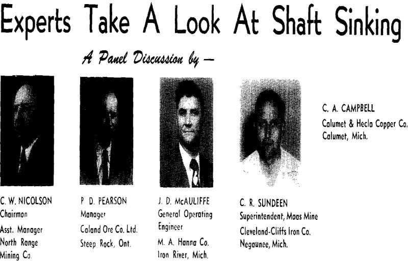
Shaft Sinking Symposium is a weighty term that could mean any number of things. However, in this case it has been possible to utilize the transcription of the Annual Meeting Session of the same title and present it in much the same manner as the experts on the panel presented it to their audience Wednesday afternoon, February 18, 1953, at the Los Angeles Statler Hotel.
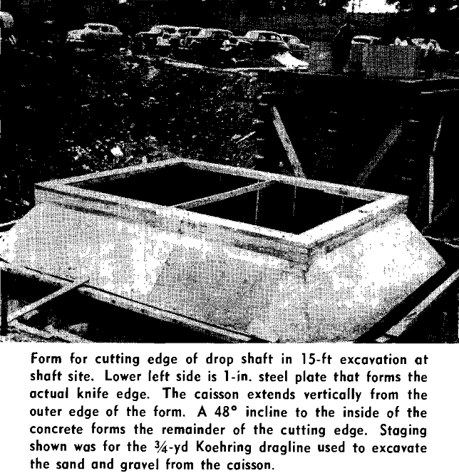
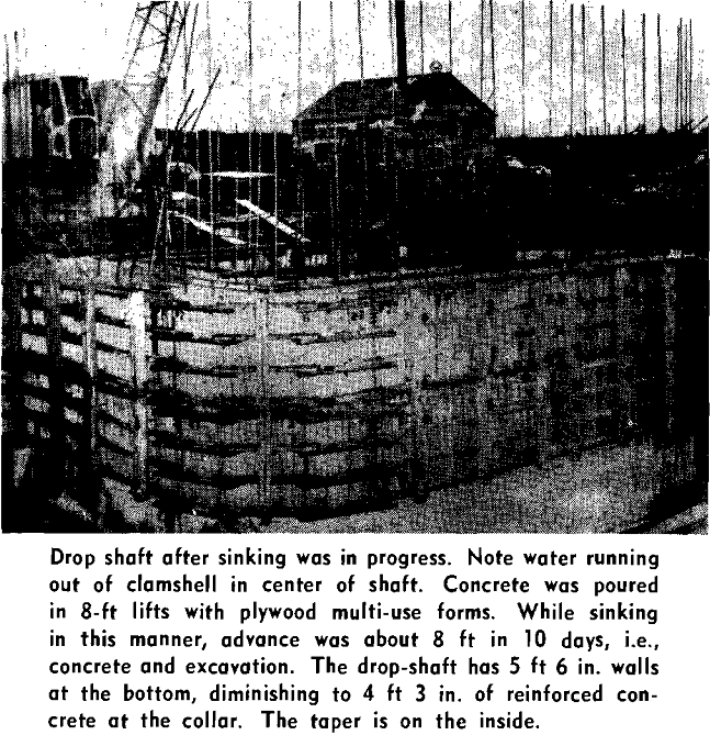
Following the failure of the rock under the caisson, the area was grouted and sheet piling was driven horizontally under the drop shaft. More grouting was done behind a temporary concrete retaining wall in the bottom of the shaft. After the final grout set, the temporary wall was removed and the material chopped away 18 in. inside the inner face of the caisson and for 6 ft below.
Hole diameter has been 1½ to 1 5/8 in., depth 4 and 5 ft. Recently, in one shaft, changing from 7 to 6 ft saved a steel change and gave greater advance, even with the additional blasting time. Drilling equipment has generally been a 55-lb jack-hammer, one shaft used a 75-lb machine. Light, fast hitting machines with 7/8-in alloy drill rods with intraset bits have not been too popular in the shafts, but one shaft is using them.
Size of crews has varied between 6 and 12 men, with the shift boss on each shift extra. This generally depends on the number of machines they want to use. There is no particularly special equipment used. We have not used any drill jumbos in shaft sinking, but it would offer many advantages if we could get a jumbo that could be set up faster than jackhammers.
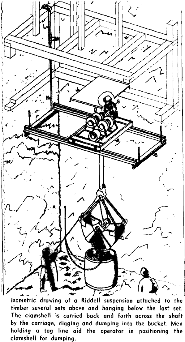
According to J. D. McAuliffe, the Riddell Shaft Mucker has not been used in any of the Upper Peninsula shafts, but he gives the following data on the machine:
- The Riddell Mucker has been adapted to shafts of the following sizes as well as those of intermediate dimensions. Smallest, rectangular,
outside of timber, 7 ft x 13 ft
Largest, rectangular,
outside of timber, 16 ft. 4 in. x 30 ft. 8 in.
Smallest, circular, neat outside, 16 ft diam
Largest, circular, neat outside, 24 ft diam - Types of Design:
(a) Two general designs of carriage are in popular use.
(1) A carriage, light in design, equipped with guides to accommodate the shaft runners, permitting the removal of the carriage from the proximity of the blast.
(2) A carriage, heavy in design, capable of withstanding the impact of blasting.
(b) Two special designs have been featured that permitted the clamshell bucket to serve all parts of a shaft without casting.
(1) For larger circular shafts an additional circular track has been introduced, permitting the conventional mechanism to revolve.
(2) For large rectangular shafts a secondary cross motion has been incorporated into the carriage, allowing the hoist motors to change position.
In all cases the track frame is designed to withstand the impact of blasting. In many instances, the track frame serves as a blasting set as well as a platform for timbering. - Monthly Penetration Records:
Case I
Progress, 309 ft in 30 days—3 shifts per day Size, outside of timber, 6 ft 11 in. x 17 ft 2 in. Number of men in shaft, including supervision, per day—19
Monthly advance per man—16.26 ft
Cubic yardage per man shift, measured in place—2.38 cu yd
Case II
Progress, 284 ft in 30 days—3 shifts per day Size, outside of timber, 6 ft 10 in. x 17 ft 8 in. Number of men in shaft, including supervision—13
Monthly advance per man—21.84 ft
Cubic yardage per man shift, measured in place—3.26 cu y
