The Steel Head Rod Mill (sometimes call a bar mill) gives the ore dressing engineer a very wide choice in grinding design. He can easily secure a standard Steel Head Rod Mill suited to his particular problem. The successful operation of any grinding unit is largely dependent on the method of removing the ground pulp. The Steel Head Rod Mill is available with five types of discharge trunnions and each type trunnion is available in small, medium, or large diameter. The types of Rod Mill discharge trunnions are:
- overflow,
- perforated overflow,
- return spiral,
- grate, and
- peripheral.
Thus the engineer can fit any one of fifteen variations of sizes and type of discharging a rod mill, into the problem on which he is working.
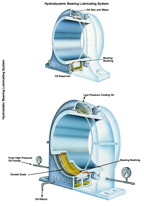
The superiority of the Steel Head Rod Mill is due to the all-steel construction. The trunnions are an integral part of the cast steel heads and are machined with the axis of the mill. The mill heads are insured against breakage due to the high tensile strength of cast steel as compared to that of the cast iron head found on the ordinary rod mill. Trunnion Bearings are made of high-grade nickel babbitt, dovetailed into the casting. Ball and socket bearings can be furnished if desired.
Head and shell liners for Steel Head Rod Mills are available in Decolloy (a chrome-nickel alloy), hard iron, electric steel, molychrome steel, and manganese steel. The heads have a conical shaped head liner construction, both on the feed and discharge ends, so that there is ample room for the feed from the trunnion helical conveyor discharge to enter the mill between the rods and head liners on the feed end of the mill. Drive gears are furnished either in cast tooth spur gear and pinion or cut tooth spur gear and pinion. The gears are furnished as standard on the discharge end of the mill, out of the way of the classifier return feed, but can be furnished at the mill feed end by request. Drives may be obtained according to the customer’s specifications.
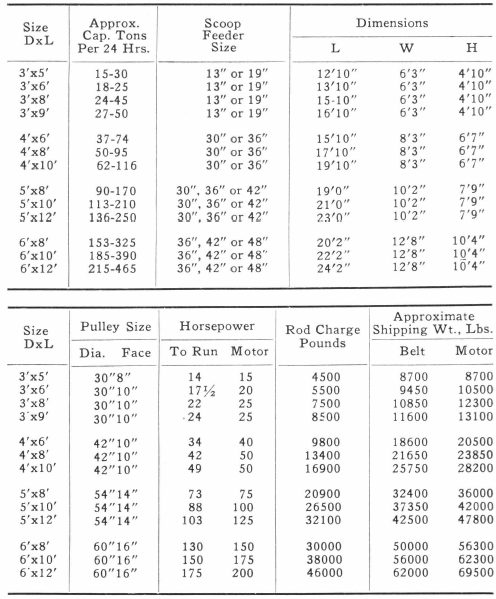
The following table clearly illustrates why Steel Head Rod Mills have greater capacity than other mills. This is due to the fact that the diameters are measured inside the liners, while other mills measure their diameter inside the shell.
Rod Mill Capacity and Sizing Table
Rod Mills may be considered either fine crushers or coarse grinding equipment. They are capable of taking as large as 2″ feed and making a product as fine as 35-48 mesh. Of particular advantage is their adaptability to handling wet sticky ores, which normally would cause difficulty in crushing operations. Under wet grinding conditions of course the problem of dust is eliminated.
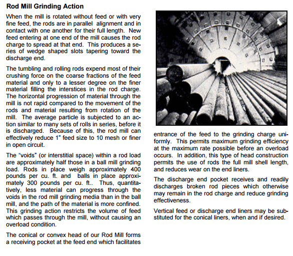
The grinding action of a rod mill is line contact. As material travels from the feed end to the discharge end it is subjected to crushing forces inflicted by the grinding rods. The rods both tumble in essentially a parallel alignment and also spin, thus simulating the crushing and grinding action obtained from a series of roll crushers. The large feed tends to spread the rods at the feed end which imparts still an additional action which may be termed scissoring. As a result of this spreading the rods tend to work on the larger particles and thereby produce a minimum amount of extremely fine material.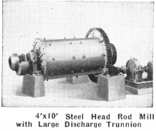
The Rod Mill encourages the use of a thick pulp coating both the liners and the rods, thus minimizing steel consumption. Continuous movement of the pulp through the rod mass eliminates the possibility of short circuiting any material. The discharge end of the Rod Mill is virtually open and larger in diameter than the feed end, providing a steep gradient of material flow through the mill. This is described in more detail on pages 20 and 21.
End Peripheral discharge and center peripheral discharge rod mills are described in detail on pages 28 and 29.
Feed and discharge heads of Rod Mills are conical in shape providing important advantages over a mill with straight heads.
- 1. They provide the essential feed pocket and also a space for the pulp to squeeze from the rod mass. This internal feed pocket permits coarser pieces of material to roll down to the toe of the rod load and be absorbed, minimizing rod spread.
- Rods will not tangle or jam.
- Wear on head liners is minimized.
- The sloping heads tend to align the rods within the mill.
- Ample space is provided to assist in inspecting and sorting rods when required.
ROD MILL SPECIFICATIONS
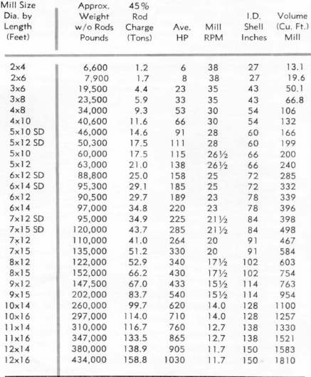
The following cost advantages should be considered when evaluating rod mill grinding:
- Rod Mills use low cost grinding media.
- Less power is required since grinding rods are not cascaded and operate at lower peripheral speeds.
- Higher grinding efficiency is obtained since there is less void space in a rod charge compared to any other grinding media. This also results in lower steel consumption.
- Our heavy rigid construction combined with the open end feature insures maximum operating time.
- Grinding rods can be kept in maximum working condition since worn rods may easily be withdrawn.
The Rod Mill is probably the most flexible type of grinding unit available. The fineness of grind and tonnage may be easily varied by altering the mill speed, rod charge or dilution.
Under dry grinding conditions the rod mill product may be altered by varying tonnage, size of feed, size and quantity of grinding media and the use of peripheral discharge ports.
Normally Rod Mills are furnished of the two trunnion design. For special applications they may be furnished of the tire trunnion or two- tire construction. These mills can be equipped with any type of feeder and type of drive, discussed separately in this catalog.
ROD MILL CAPACITIES
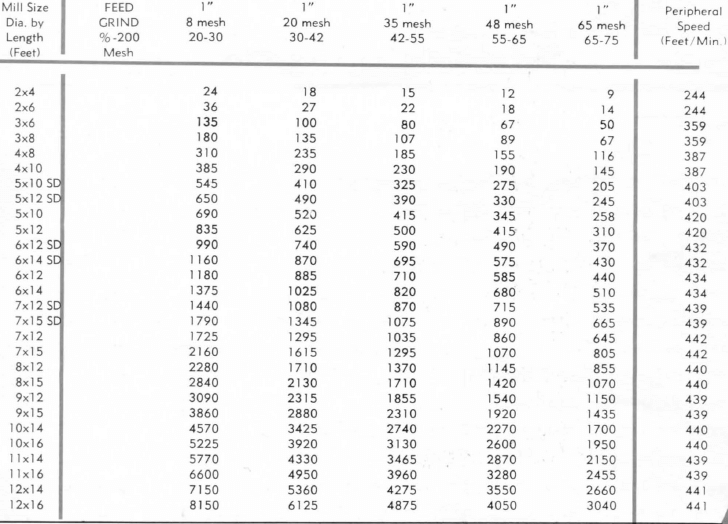
The above tables list some of the most common Open End Rod Mill sizes. Capacities are based on medium hard ore with mill operating in closed circuit under wet grinding conditions at speeds indicated. For dry grinding, speeds and power are reduced and capacities drop 30 to 50%.
ROD MILL General Arrangement-Dimensions
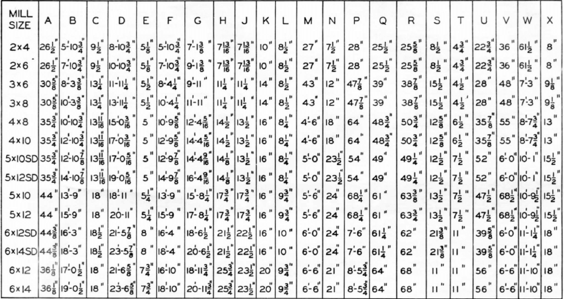
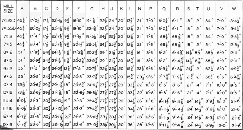
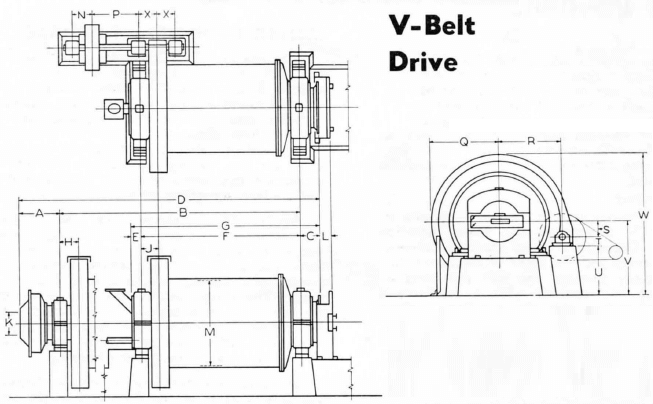
The above dimensions are approximate and for preliminary use only. Right hand mills are shown. For left-hand mills put drive on opposite side. Drive may also be located at discharge end.
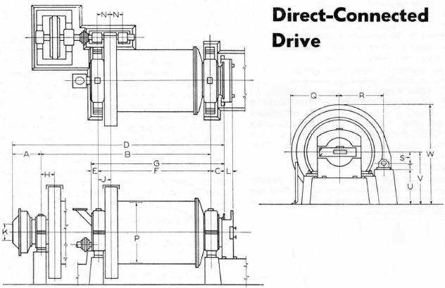
The above dimensions are approximate and for preliminary use only. Right-hand mills are shown. For left-hand mills put drive on opposite side. Drive may also be located at discharge end.
PERIPHERAL DISCHARGE ROD MILLS
END PERIPHERAL DISCHARGE
The End Peripheral Discharge Rod Mill is designed to produce a minimum amount of fines when grinding either wet or dry. Material to be ground enters through a standard trunnion and is discharged through port openings equally spaced around the mill periphery. These ports are in a separate ring placed between the shell and the discharge head.
Wet Grinding ROD MILLING
The construction of the end peripheral discharge mill emphasizes the principle of grinding. Due to the steep gradient between the point of entry and the point of discharge the pulp flows rapidly through the mill providing a fast change of mill content with a relatively small amount of pulp within the grinding chamber.
The sloping or conical shaped feed head proves ample space for a feed pocket to accommodate large quantities of material and assure their entrance into the grinding rods. Any type of feeder listed on pages 22 and 23 can be furnished for these mills; however, since the mills are not usually operated in closed circuit grinding, the drum or spout feeder is normally preferred.
The pulp discharge from the mill is collected by a housing around the discharge ring and may be directed to either side of the mill or immediately below the mill centerline.
Dry ROD MILL Grinding
No other type of mill is so well adapted to dry grinding materials to -4 or -8 mesh in single pass with the production of a minimum amount of fines. A major factor in dry grinding is the rapid removal of finished material to prevent cushioning of the rods. This is accomplished in the End Peripheral Discharge Rod Mill.
The free discharge feature permits the grinding of material having a higher moisture content than with other types of rod or ball mills. Our Peripheral Discharge Mills have found wide application in grinding coke and friable non-metallics, material for glass, pyroborates, as well as gravel to produce sand. Another application is for grinding and mixing sand lime brick materials. The rod action gives a thorough mixture while grinding of the hydrated lime and sand.
A dust-proof housing is provided to deliver the finished product underneath the mill. Any type of feeder can be provided but again the drum or spout type feeder is preferred.
For specifications of End Peripheral Discharge Rod Mills use table of standard open end rod mills given on pages 24 and 25. The capacity of the end peripheral discharge rod mill is slightly higher than shown for the Open End Rod Mills.
CENTER PERIPHERAL DISCHARGE ROD MILL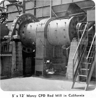
The CPD (Center Peripheral Discharge) Rod Mill has been developed to produce sand to meet U. S. Government or State specifications. It has also found application in grinding friable non-metallics, and industrial materials and ores which tend to slime excessively. Another application is in the field of “abrasion milling” on ores such as found on the Mesabi Iron Range. In this latter application true grinding is not desired, but more of a surface scrubbing of the individual particles.
Again with this construction grinding may be done either wet or dry. In this design, however, feed enters both ends by means of feeders and is discharged at the center through rectangular discharge ports equally spaced around the mill periphery. The center discharge openings are generally contained in a separate ring placed between shell halves. The ground material is discharged and directed to either side or directly under the mill by the use of a discharge ring housing.
In standard rod-milling it will be found that rods spread apart at the feed end in the amount of the maximum size of feed entering the mill. In the center peripheral discharge mill the rods are spread at both ends and parallel throughout the length of the mill. This feature results in more space between the rods and thereby lessens the amount of fines produced. Furthermore, fines are also diminished because the material moves rapidly through the mill due to the steep gradient of travel and the distance of travel is reduced by half. Similarly time of contact with the grinding media is reduced by half.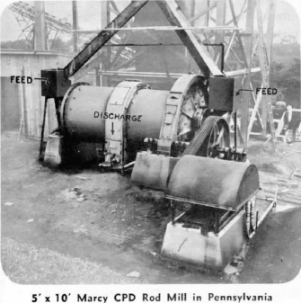
Another center peripheral discharge advantage is that a cubical shaped particle is produced. Maintenance is negligible and grinding media is relatively inexpensive. Other types of sand manufacturing equipment lose efficiency with wear and require excessive maintenance. This loss of efficiency increases rapidly as hardness of feed increases. The Center Peripheral Discharge Rod Mill can be easily maintained at peak operating efficiency by the periodical addition of rods. CPD Rod Mills give a wide range of flexibility to sand plant operation. By changing the rate of feed, pulp dilution (wet grinding), and discharge port area it is possible to produce and blend sand of virtually any fineness modulus and maintain it within Government specifications.
Unlike many crushers or grinders the CPD Mill can easily handle wet or sticky material. When grinding wet, the dust nuisance is completely eliminated. For dry grinding applications the mill is furnished with a dust proof discharge housing.
Various items must be considered in computing the cost of producing manufactured sand. These include wear on the constituent parts, power consumption, lubrication, labor and general maintenance. Maintenance of the center peripheral discharge mill is definitely much lower than that of any other sand manufacturing machine. The greater portion of the wear which takes place is on the inexpensive high carbon steel rods. Field installations show an average of less than 1 # per ton of sand ground as rod consumption, and from 0.08# to 0.10# per ton of sand ground as the steel liner wear. The overall cost of mill operation, exclusive of amortization, is generally less than 30c per ton (year 1958).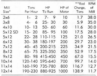
Every possible operating convenience has been incorporated in the center peripheral discharge mill design. On most sizes the trunnions are carried in large lead bronze bushed bearings. The interior of the mill is readily accessible through these large trunnion openings. The peripheral ring housing is furnished with a door for inspection and another lower door to facilitate sampling of the mill discharge. Covers for the discharge ports are furnished allowing any variation in discharge area which might be desired.
Given below are approximate capacities for several sizes of the center peripheral discharge mills. Such capacities are expressed in dry tons per hour, based on -¾” x 4 mesh screened feed of medium hard gravel. Mill discharge is generally less than 5% + 4 mesh in wet open circuit operations, for dry grinding work reduce the capacities indicated by approximately 30% to 50%.
Rod Mill Working Principle & Components
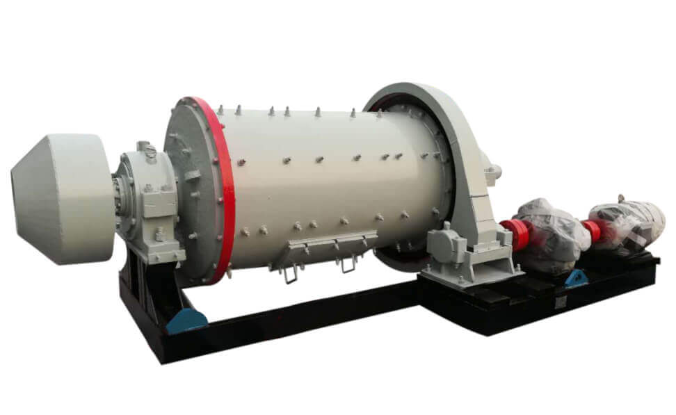
A Rod Mill has for Working Principle its inside filled grinding media, in this case STEEL RODS. These rods run the length of the machine, which is most commonly between eight and sixteen feet in length. The diameter of these rods will range from, when new, between two and four inches. The rods are free inside the mill. When the mill is turned, the rods tumble against one another grinding all the ore that is between them to aid in the grinding, water is added with the ore as it enters the mill. So from that you can see why it is called a wet tumbling mill. The ore is ground wet and the mill revolves. This causes the grinding media inside of it to tumble grinding the ore.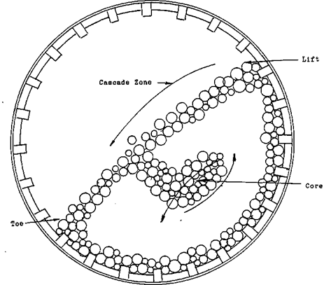
Historically there has been three basic ways of grinding ore, hammer mills, rolls, or wet tumbling mills. Hammer mills and rolls are not used that often and then usually only for special applications as in lab work or chemical preparation.
The type of mill that is used for grinding ore in a modern concentrator is the wet tumbling mill. These mills may be divided into three types ROD MILLS, BALL MILLS and AUTOGENOUS MILLS. In the first type, the ROD MILL, the ore is introduced into the mill.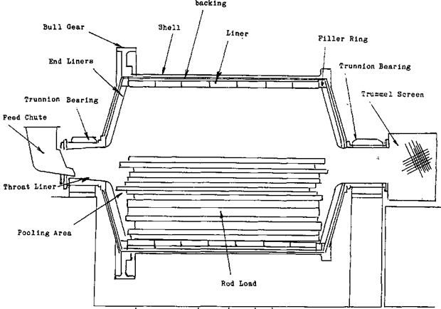
Before we get to the operating skills and theories needed to operate this machine let’s go over the construction of it.
If we cut a mill in half and examine the construction of a rod mill and its components here is what we will see.
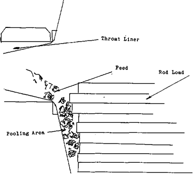
From the trunnion liner out wards first we will come to the FACE PLATE. It is slightly concave to create the POOLING AREA for the rock to collect in before entry to the ROD-LOAD. On the outside attached to the face plate is the BULL GEAR. This gear completely circles the mill and provides the interface between the motor and the mill. The bull gear and drive line may be at the other end of the mill instead. There are advantages and disadvantages to either end this will be explained later when we are discussing the motor and drive line. But for now back to the face plate, attached to the other side of the face plate is the SHELL. The shell is the body of the mill. On the inside of the mill there are two layers of material, the first layer is the BACKING for the liners. This is customarily constructed from rubber but wood may be used as well. The purpose of this backing is two-fold, one to absorb the shock that is transmitted through the liners from normal running. And to provide the shell with a protective covering to eliminate the abrasion that is produced by the finely ground rock and water. Without this rubber or wood backing, the life of the mill is drastically reduced due to metal fatigue and simply being worn away.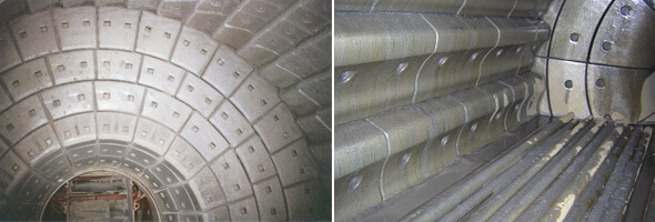 For those of you aren’t familiar with METAL FATIGUE I will explain. When metal is continually pounded or vibrated, the molecular structure of the metal begins to change, it is said to CRYSTALLIZE, and the metal becomes hard and finally loses all ability to give with the vibration. Thousands of microscopic cracks will begin to appear, as the fatigue of the metal continues, these cracks will grow to become major problems.
On top of this backing is the LINERS themselves. There are many different patterns and types of liners depending upon the job that they are doing and the design of the mill.
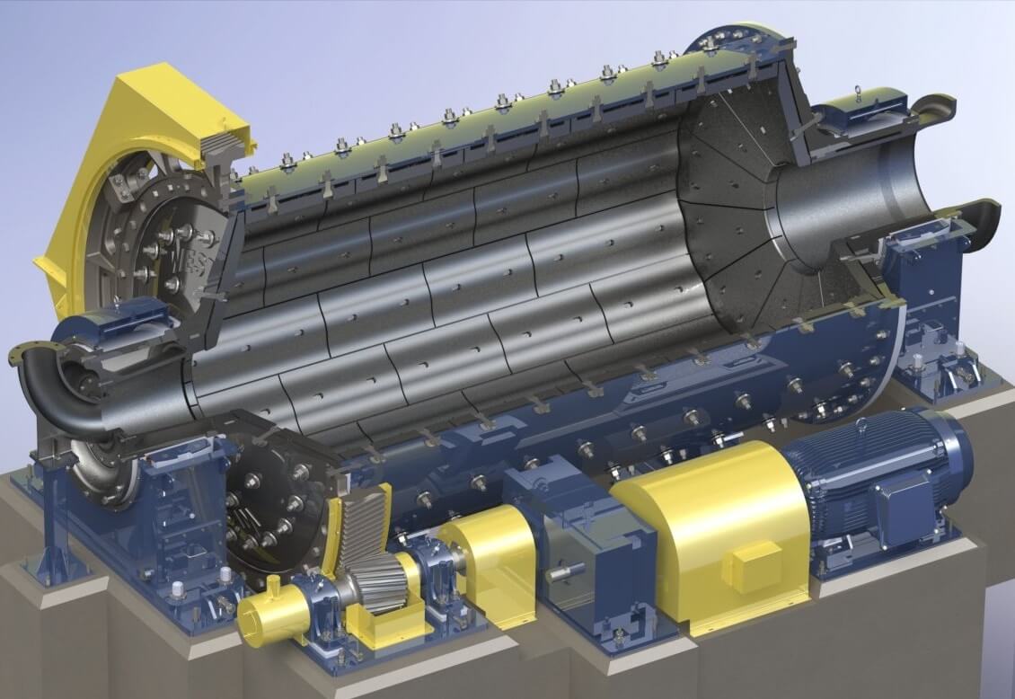
Later for interest sake we will explain the difference in some of them, but for now let’s stay with identifying the parts of the mill. We have already mentioned the trunnion liner so let’ start from there.
The trunnion liner may also be referred to as the THROAT LINER. You will find that many of these parts will be called two or even sometimes three names, All I can say is try not to let it confuse you, The name isn’t as important as the job that it does. As long as everybody that you work with agree on which name to use, it doesn’t matter that much.
Next to this liner is the END LINERS, or to some, the PACE PLATE LINERS. The FILLER RING which is next is not standard in all mills, some mills have them, and some don’t. Their job is to fill the corner of the mill up so the shell will not wear at that point. They don’t provide any lift to the media, in fact quite often the media will not come into contact with them at all, but what they do is make changing liners that much easier. With different liner designs the replacement of a single liner may be quite difficult and to change one could become a lengthy project.
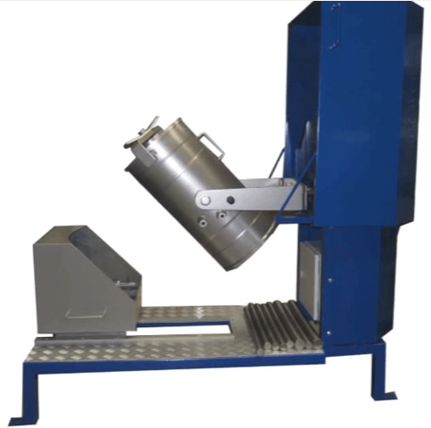
The liner that butts into the filler liner is known as a BELLY LINER or SHELL LINER, and in some designs LIFTER BARS. These liners and/or lifters give the media its CASCADING action and also receive the most wear. They cover the complete body of the mill and have the largest selection of types to choose from.
As the two ends of the mill are the same there isn’t any reason to go over the other face plate. The discharge trunnion assembly is very much like the feed trunnion except that, it won’t have a worm as part of the liner. Instead of a feed seal bolted to it, it may have a screen.
This is called a TRUMMEL SCREEN and its purpose is to screen out any rock that didn’t get ground as well as any TRAMP METAL or REJECT STEEL that may be coming out of the mill. Reject steel is the old grinding media that has been worn so small that it comes out of the mill. If this tramp metal and steel is allowed to get into pumps and classifiers damage and plug- ups may be caused.
With regards to Rod Mills, let us start by identifying the different portions of the rod load as it goes through one revolution, as you will see, each of these areas will hold interest for the Grinding operator.
 |
 |
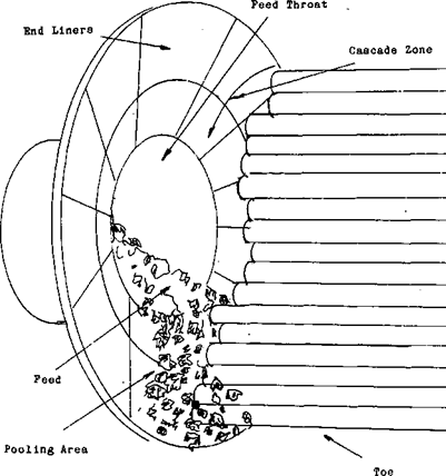
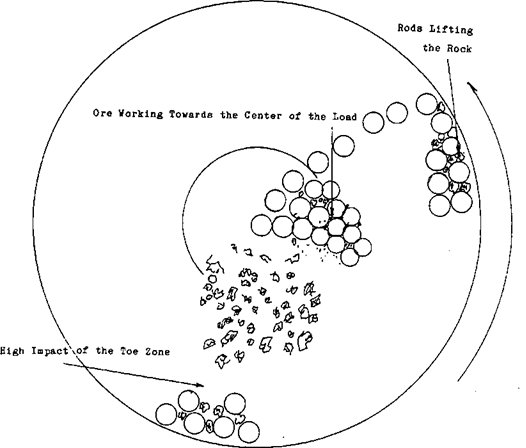
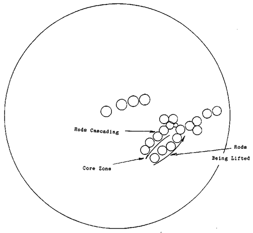
As the rod mill turns, the rods are carried by the lifting portion of the liners. The height that they are lifted is referred to as the “lift” of the liners. As they roll off of the liners, the rods enter the “cascade zone”. The rods roll through the cascade zone until they come to the “toe” of the load. At this point the rods come to rest in relation to the shell of the mill. The liners lift the rods back to begin the cascade again. You will notice, that as you go deeper into the rod load, the rod movement becomes less and less until the movement is very slight at the deepest part. This area is called the “core” of the load. As a description of the normal grinding action, the rods and the ore react together like this. The ore enters-the mill and is deposited in the pooling area directly under the feed trunnion.
This pooling area is formed by the CONCAVE PORTION of the face plate of the mill and the rods.
This pooling area allows the large rock to fall towards the outside portion of the load, the TOE area. This is the zone with the greatest movement in it, which means the area that will have the highest impact on the ore.
The rock will be carried up by the rods as they go through the CASCADE ZONE reducing the size of the rock. As each particle of ore becomes smaller it will work towards the CORE ZONE while travelling the length of the mill. That makes for a rather neat arrangement doesn’t it. The larger rock is deposited in the area where the maximum impact from the rod load occurs and then as each particle gets smaller it slowly travels inwards towards the centre of the load.
This is where the maximum surface contact takes place, producing the finer grind. When the ore has travelled from one end of the mill to the other end it will have completed its grinding cycle in this mill. As it exits the rod load it will be deposited in another POOLING AREA prior to leaving the mill by way of the DISCHARGE TRUNNION.
Prom that you can see how a mill will become over loaded. If for some reason the rock begins to separate the rods over their entire length, the larger rock will prevent the intermediate rock from being ground. Which in turn will begin to invade the area that the fine material is being ground in. As the rods become separated through the entire load, the grind will get progressively worse until the unground rock is in the discharge pooling area. At this point, the operator will notice, that large rock is being discharged from the discharge trunnion.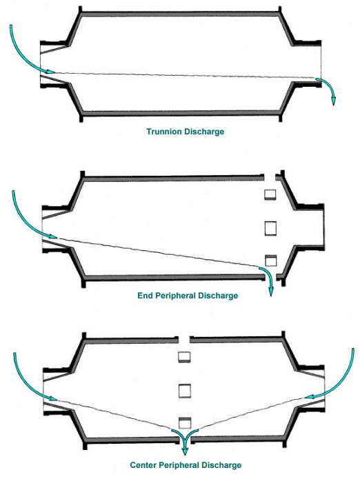
During normal operations there is usually a certain amount of this larger rock that won’t get ground. These are known as ’’REJECTS” and they serve as one of the tattle tales as to how the mill is grinding. If there is an increase of these rejects then the mill isn’t grinding that well and the operator will have to do something about it. If he doesn’t the mill load will continue to climb, until the rods in the lifting zone are completely separated. When this happens those rods will have quit grinding.
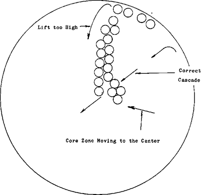
There is a visual warning of this happening that the operator can take advantage of. The lift on the rods will get higher and higher until they are being carried to the very top of the mill before cascading. I think falling would be a better word for it though.
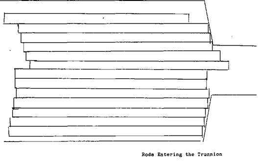
As this is happening, the core of the load will be slowly moving away from the shell towards the center of the mill. This is because the volume of the mill is being filled with unground rock. This will continue until the load hits a critical volume and a critical density. The rock still coming in to the mill will have to have some where to go so it tries pushing the rods out of the mill. Unfortunately they won’t make it, the first hunch of rods that get far enough into the discharge trunnion will be- hit by the rest of the load bending and twisting them until they look like SPAGHETTI. This usually shuts the mill down for a couple of days while the millwrights cut the bent rods out of the mill.
On the other end of the scale, if the density is to light, the rod load will become too active, not having the solids in the mill to cushion the impact of rod on rod and rod on liner. As the rods enter the cascade zone, the pattern of the movement of the rods will be different. Instead of having a tightly tumbling mass of rods, the rods will be separated. The lift will be higher and the cascade will form more of an arc. The impact of the rods on the rock will be less because there will be more give in the rod load, with high amount of steel on steel causing the rods to bounce.
Rod Mill Grinding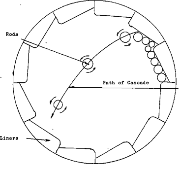
Lets look at how these Rod mills work, as I mentioned earlier there are steel rods inside the mill, it is their job to do the actual grinding. If you look at the mill in a cross section of an end view. You will get a very good illustration of the grinding action, of the mill.
The LINERS provide the tumbling action of the rods. When the mill rotates the rods are lifted until they roll off of the liners, this is known as CASCADING. The ore enters the mill at the feed end, as the rods cascade and tumble, the rock is caught between the rods and is ground. The size that the rock will be ground to is dependent on the amount of time the ore is in the mill, how many rods there are in the mill V and the size of the incoming ore.
