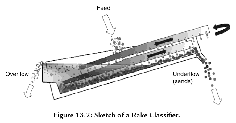
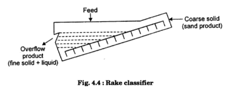
Let me describe a cycle of the Rake Classifier arm to you. The arm, with a series of rakes along its length, drops into the flow of slurry and is pulled upwards. Some of the fine material will flow over, the top of the rake. The rest will be pulled along with the coarser heavier material up the incline. When the arm reaches the end of its throw it will lift the rake out of slurry allowing the material to continue back flowing down towards the fine ore discharge. As the slurry begins to flow downwards, further classification takes place. Before the coarse material is able to travel out of range of the next rake on the arm it will be picked up again and pulled up the incline a bit further. The slurry will continue to be manipulated in this manner until all of the fine material has been washed out of it and the coarse is discharged at the other end of the Rake Classifier by its rakes.
 |
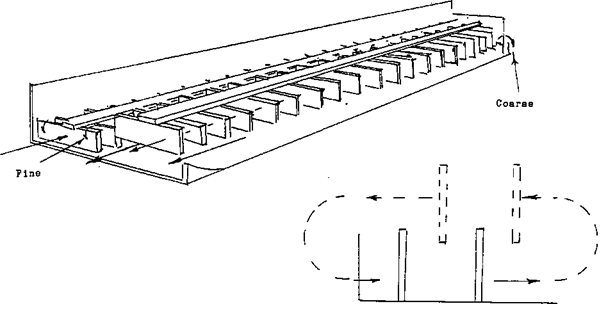 |
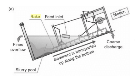
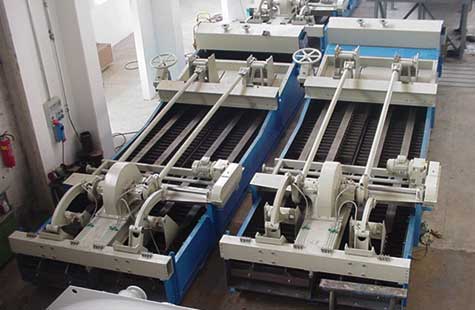
The rake classifier (Figure 9.18(a)) uses rakes actuated by an eccentric motion, which causes them to dip into the settled material and to move it up the incline for a short distance. The rakes are then withdrawn, and return to the starting-point, where the cycle is repeated. The settled material is thus slowly moved up the incline to the discharge. In the duplex type, one set of rakes is moving up. while the other set returns; simplex and quadruplex machines are also made, in which there arc one or four raking assemblies, respectively.
https://www.flsmidth.com/ and https://www.metso.com/
Rake Classifier
The rake classifier such as the Dorr classifier consists of a rectangular tank with a sloping/inclined bottom. The tank is provided with movable rakes (reciprocating rakes). The feed in the form of a suspension (slurry) is introduced continuously near the middle of the tank. The lower end of the tank has a weir overflow (discharge weir) from which the fines that are not settled leave with the overflow liquid. The heavy material (coarser particles) sink to the bottom of the tank. The rakes scrap the settled solids upward along the bottom of the tank toward the top of the tank for discharge from a sand-discharge chute. The reciprocating rakes keep the slurry in continuous agitation. The time of raking stroke is so adjusted that fines do not have time to settle and so remain near the surface of the slurry, while the heavy particles have time to settle
[they settle, scrapped upward and removed as a dense slurry (called the sand)].
Particle Classification
Of the various classifiers employed in conjunction with ball and rod mills, the only ones at all widely used are those made under the Dorr-Oliver Company’s patents. They can be divided into two classes, one consisting of the “straight” type and the other of the ‘‘ bowl ” type of classifier.
Straight RAKE Classifiers
Fig. 17 gives a general view of the Dorr Duplex Classifier, Model D, many of which are still in use, though this type is no longer made. The operation of the mechanism can be seen from Fig. 18.
The machine consists of a settling tank in the form of an inclined trough with its upper end open, in which are suspended the rakes (3). The pulp to be classified enters the tank by the feed trough (1) ; the heavy material settles to the bottom, but any particles small enough to be discharged overflow the lip (2) in a continuous stream. The upper end of each rake is suspended by a link from a rocker arm (5) to which is attached a roller (6), the shaft supporting the rocker arm being fixed to the frame work that carries the driving mechanism. The roller (6) presses against the cam (7), which is keyed to the crankshaft (8) and revolves with it. The lower end of each rake is suspended by a link from a bell crank (10), the shaft of which passes through one end of a lifting lever (11), which in turn is carried on a framework fixed to the sides of the tank, but which remains stationary while the bell crank (10) is moving. Should the classifier be stopped and the tank become choked with sand, the rakes can be lifted clear by means of a worm gear (13) which raises the lifting lever (11) and so pulls up the whole assembly supporting the lower end of the rakes. The bell crank (10) is connected to the rocker arm (5) by a reach rod (12) ; each rake is also linked by a connecting rod (4) to a crank (9) which is cast in one piece with the cam (7).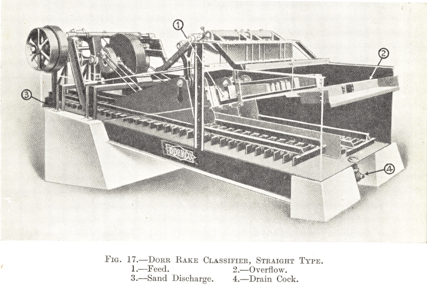
The crankshaft is driven at a slow speed through a reducing gear. As it revolves the cranks (9) move the rakes backwards and forwards parallel to the bottom of the tank, but the cam (7) is so shaped that, when a rake is at the end of its strokes at the lower end of the tank, the rocker arm (5) and the bell crank (10) drop it so that it is just clear of the bottom. The crank (9) then pulls it up the tank by means of the connecting rod (4) to the full extent of its stroke, dragging up any sand that has settled to the bottom. At the end of this upward stroke the rake is raised by the cam through the rocker arm and bell crank so that, on the return stroke of the crank (9), it moves down clear of the sand which has been settling on the bottom of the tank. The downward stroke of the rakes gives the pulp a jigging motion which helps to keep the fine material in suspension, while the flow of the pulp from the ball mill produces a continuous overflow past the lip (2) which carries over any particles that are small enough to be discharged. The oversize sand, on the other hand, is dragged up the classifier by the rakes as fast as it settles and is finally discharged at the open end of the tank at the top of the slope in a comparatively dry condition.
Model D Classifiers are made in Simplex, Duplex, and Quadruplex types—that is, with one, two, and four rows of rakes respectively. Simplex machines are made in two sizes, 3 ft. and 4 ft. wide respectively, the corresponding Duplex classifiers being twice and the Quadruplex four times as wide.
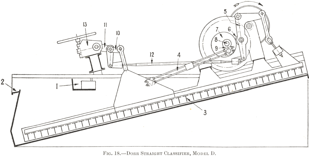
Table 14 gives particulars of the overflow and raking capacity of these classifiers at different settings. Their power requirements are as follows :—

The h.p. figures represent sizes of motors ; the actual power consumed will be about two-thirds of these amounts.
When a classifier is working in closed circuit with a ball or rod mill, it is usually possible to arrange their relative positions so that the discharge of the mill flows to the feed trough of the classifier while the oversize that is raked up the slope falls by gravity into the feed box of the mill; such an arrangement is shown in Fig. 9. The length of the classifier does not affect its operation and it can, therefore, be made of the exact length required to suit the mill.
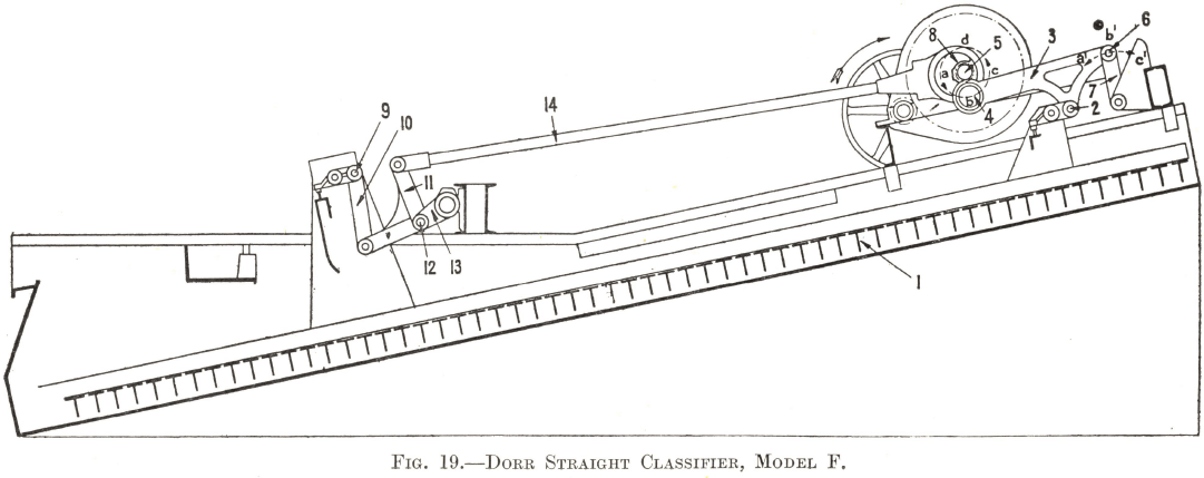
The Model D Classifier has been superseded by Model F, which incorporates a new type of head-motion without a cam and with fewer moving parts. The Model D cam and roller type of head-motion restricts the speed at which the rakes can be run, since the roller bounces on the cam if the latter rotates too fast; the absence of a cam in the Model F mechanism makes a higher speed possible and gives the classifier a greater raking capacity in consequence. Model F Classifiers are being installed in most new installations in preference to Model D.
The operation of the mechanism can be seen from Fig. 19. The upper end of each of the rakes (1) is suspended by a rake hanger shaft (2) from a projection on the connecting rod (3). A crank (not shown in the diagram) connects shafts (4) and (5) and is keyed solid with shaft (5) , which is driven through a reducing gear as in Model D. As the crankshaft (5) rotates it moves the end (4) of the connecting rod (3) round in a circle as indicated by the dotted line ; the other end of the connecting rod is secured by a shaft (6) to the front link (7), the lower end of which pivots about a shaft fixed to a support on the tank. The position of the lower end of the link (7) being fixed, its upper end moves backwards and forwards in the path shown by the dotted line as the connecting rod oscillates. As the point (4) falls from (a) to (b) the point (6) rises from (a¹) to (b¹), and as the point (4) rises from (b) to (c) the point (6) falls from (b¹) to (c¹). The dimensions of the parts are so arranged that the movements of shafts (4) and (6) combine to give the required motion to shaft (2) carrying the rake, which is thus made to move up parallel with the bottom of the tank as the end of the crank moves from (a) through (b) to (c), but during the other half of its travel from (c) through (d) to (a) the reverse takes place ; both ends of the connecting rod rise as the crank moves from (c) to (d) and fall as it moves from (d) to (a) with the result that the rake is lifted and carried down clear of the sand ready for another upward stroke along the bottom of the tank. The lower end of each rake is moved in a similar way. It is suspended from a hanger shaft which is supported by the rear link (10) and the bell crank (11) ; the latter is pivoted on a shaft (12) held in place by the lifting lever (13). A support fixed to the sides of the tank carries the whole lifting lever assembly, including a worm gear (not shown) which can be used to raise the bottom end of the rakes in case of necessity exactly as in the Model D Classifier. The top end of the bell crank (11) is connected by a reach rod (14) to an eccentric (8), the centre part of which is
cast in one piece with the crank.
The principle of the mechanism is the same as at the top end ; as the rake is pulled up the tank, the rise of the bell crank (11) compensates for the fall of the hanger shaft (9), and vice versa, but, as it moves down, both bell crank and hanger shaft rise during the first half of the downward stroke and fall during the second half, thus exactly duplicating the motion of the assembly supporting the top end of the rake.
Model F Classifiers are made in Simplex, Duplex, and Quadruplex types, their respective widths being the same as those of Model D. Table 14 can be taken as a basis of the overflow and raking capacity of Model F machines at different settings, although, on account of its smooth operation, the mechanism can be run at considerably higher speeds than those in the table, with corresponding increase in sand-raking capacity. The h.p. consumption is less than that of Model D owing to the reduction in the number of moving parts and the smooth positive operation of the mechanism.
How to Control a Rake Classifier
There are three adjustments that can be made to regulate the mesh of separation of a classifier:
- The speed of the rakes, which regulates the amount of agitation and the jigging motion of the pulp as well as the tonnage of oversize that can be raked up the slope.
- The slope of the tank, which determines the volume of pulp in it and the area available for settlement of the solids.
- The W/S ratio of the pulp in the classifier.
The first two adjustments are fixed before the classifier is installed and they cannot be altered while the machine is running ; the controlling factors are so well known that it is seldom necessary to make a change after the machine has been erected.
The third adjustment is the method by which the operation of a classifier is controlled while the plant is running. The addition of water is always necessary because the ball mill discharge seldom contains less than 70% of solids while a classifier is never run with more than 50% of solids. The effect of the addition of water to a classifier is to determine the rate at which the solids will settle ; in a thick pulp they will settle more slowly than a thin one. It follows that the coarser the overflow product required, the thicker should be the pulp, and vice versa. It must be understood that an increase in the volume of water, provided that the tonnage of solids remains the same, does not tend to carry coarser particles of ore past the overflow lip ; it has exactly the reverse effect—it increases the settling rate and makes the overflow finer.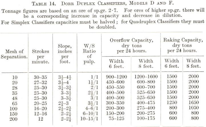
It will be seen from Table 14 that a separation finer than 100 mesh is likely to require a pulp in the classifier with less than 20% of solids. Since most flotation machines cannot be run economically with a pulp as thin as this, some means is needed of thickening it before flotation in installations where fine grinding is practised. A thickener can be used for the purpose, but the long contact period of the ore with water frequently results in “over-conditioning” of the pulp or undesirable oxidation of the mineral. The bowl classifier is designed to meet the difficulty and it is considered better to use it whenever possible in preference to a straight classifier followed by a thickener.