Table of Contents
Shaft Stations, Storage, and Loading Pockets
Arrangements for handling ore and waste at the shaft will depend on the method of hoisting (whether in buckets, in cars on cages, or in skips); the tonnage and physical characteristics of the ore; whether two or more classes of ore must be hoisted and kept separate; the method employed for transporting the ore on the levels and the type and size of cars; and the inclination of the shaft.
Hoisting in Buckets
In mines having a small output the ore may be hoisted in buckets such as those already discussed under the caption, “Equipment, Methods, and Costs of Shaft Sinking.’’ Even relatively large tonnages may be handled in this way, as in the Tri-State zinc and lead district, where buckets or “cans,” as they are termed locally, have been employed for years for hoisting 300 or 400 tons or more per shift;
it is reliably reported that 150 cans or 90 tons per hour can be hoisted by this method.
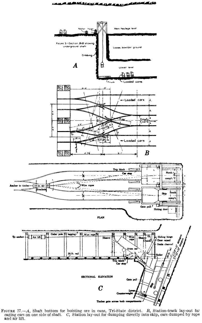
In this district the practice has been to use cans of 1,200 to 1,400 pounds capacity, which are transported to the faces of the flat stopes on small four-wheel, flat-top trucks running on light steel rails. When loaded, these cans are trammed, usually by hand or mule, to a siding, where they are made up into trains and hauled to the shaft bottom (fig. 77, A). Here men known as bumpers uncouple the trucks and push them, one at a time, to a spot directly under the center of the shaft.
A man called a hooker is stationed at this point; it is his duty to detach the empty down-coming buckets and hook the loaded buckets on the hoisting rope. A hook is attached to the end of the wire hoisting cable, and as the empty bucket or can comes within reach
of the hooker he swings it to one side and lowers it onto an empty truck placed there by the bumper. He quickly detaches the hook from the empty and attaches it to the loaded can; it is then hoisted to surface, where it is dumped by the hoist operator and returned to the shaft bottom. The hoistman and hooker work as a team and become so proficient that no signals are required as long as there is a supply of loaded cans at the bottom. The hoist is mounted in the head frame over the shaft, and the hoistman can tell by the behavior of the rope just what is going on at the bottom. The hooker becomes so adept that the unhooking of the empty and hooking of the loaded can are accomplished in one motion.
In some small mines the ore is trammed to the shaft in small cars and either dumped directly into the bucket or into a small loading pocket provided with a chute and gate, whence it is drawn into the bucket. When dumped direct, a hinged apron or spout is required to conduct the ore into the bucket without spilling.
Hoisting in Cars on Cages
Although hoisting in skips has largely replaced hoisting in cars at most modern metal mines, the latter practice is still employed and under some conditions has certain advantages that may outweigh the disadvantages. Thus in mines where two or more grades or classes of ore in addition to waste must be hoisted separately, it would be necessary, when using skips, either to have a separate pocket for each grade of ore and another for waste or, if there is only one pocket, to clean it carefully when changing from one grade or class to another. The disadvantages of the latter practice are more apparent when rapid hoisting is required, and it may be necessary to provide long sidings at the stations on which to assemble cars according to classes of ore. This calls for additional excavation to make room for necessary trackage and involves investment in more cars than would be needed otherwise. If separate pockets are provided, and especially if they have to be duplicated on each of several hoisting levels, the cost of preparation is high, and if ground conditions around the shaft are bad the excavations may weaken the shaft considerably.
Timber, drills, steel, explosives, and other mine supplies and equipment usually can be taken underground more easily in cars or on flat trucks than in a skip. Another advantage sometimes claimed for hoisting ore and waste in cars on cages is that if the shaft is not too busy the same cages may be used for hoisting ore as for handling men and supplies.
Arrangements for caging cars at the shaft stations vary. In some mines stations are cut on both sides of the shaft. The loaded cars are fed onto the cage on one side and push the empty car off on the other side, an arrangement common in coal mines but less so in metal mines. The loads may run down to the shaft by gravity or be pushed by hand or mechanical means on a level track. When run by gravity it is necessary to provide automatic car stops on the track close to the shaft to prevent movement of the cars except when they are intentionally released by the eager.
In other mines the station is cut only on one side of the shaft so that the empty car must be pulled back off the cage before the loaded car can be pushed on. Where space is at a premium, the floor of the station may be covered with steel plates (turn sheets), on which the cars may be shifted about without using tracks. This practice was common for many years and is still used to some extent, especially in development work. Where more room is available or can be made so, the work of the cagers is lightened by bringing the mine tracks up to the shaft in alinement with the tracks on the cages (fig. 77, B). Switches and cross-overs are provided for pulling the empties off to one side to allow caging the loaded cars. Besides lightening the
the labor, the track system is safer; turn sheets become wet and slippery and are likely to cause bad falls.
Hoisting in cages is considerably slower than hoisting with skips, due to the smaller net load that can be hoisted in a shaft of the same size and to the time required for caging cars at the shaft stations and on surface and usually requires more labor.
Hoisting in Skips
Skip hoisting now is employed commonly in metal mines after they have reached the regular production stage. Storage pockets and loading chutes usually are provided at the shaft, although where the output is small and the shaft is not overloaded, mine cars may be dumped directly into the skips, a short chute or apron being used to direct the flow of the ore; the chute can be hinged to fold up out of the shaft after the skip has been loaded. Figure 77, C, shows the plan and elevation of a station where cars are dumped directly into the skip.
For large output, storage pockets are essential, and skip-loading devices greatly expedite hoisting and speed the entire operation. Pockets should be large enough to permit immediate dumping of cars or trains and their prompt return to the chutes for reloading.
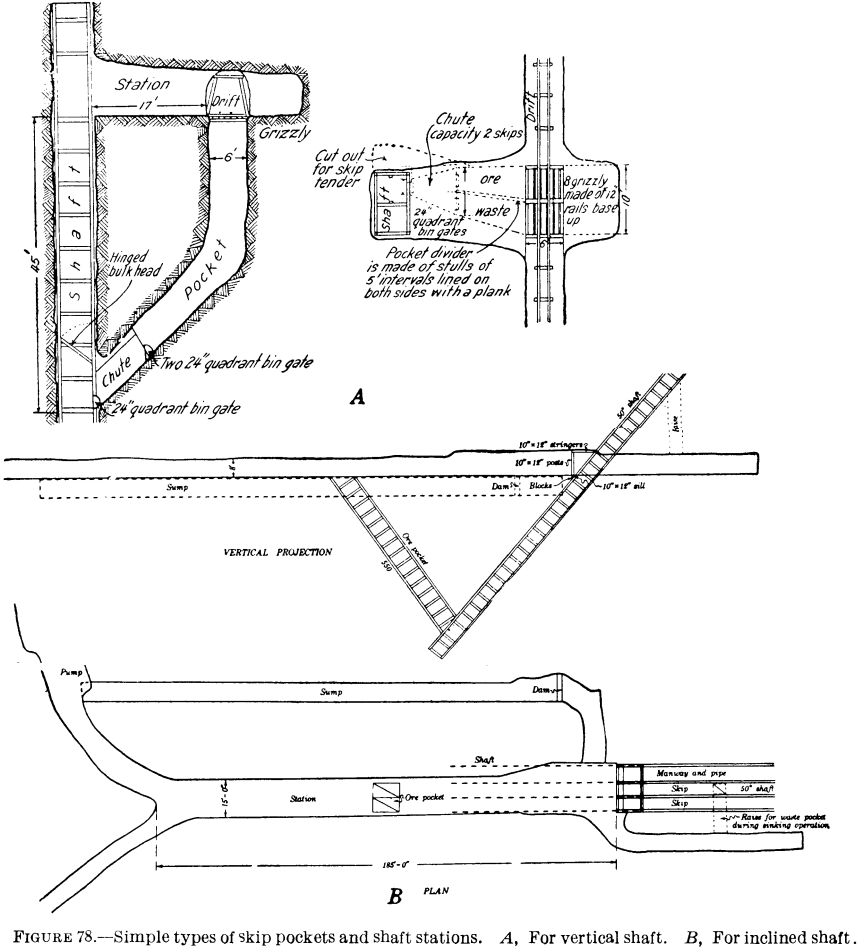
Figure 78, A, shows a plan and section of a simple type of skip pocket and shaft station. The ore cars are dumped into the pocket, which is covered by grizzly bars on which large chunks are caught and broken before they enter the pocket. A minimum amount of excavation is required and the shaft is not weakened by this style of pocket, but to obtain storage capacity the loading station must be considerably below the level. In this particular installation ore is hoisted in only one compartment of the shaft. Figure 78, B, shows a similar arrangement at an inclined shaft.
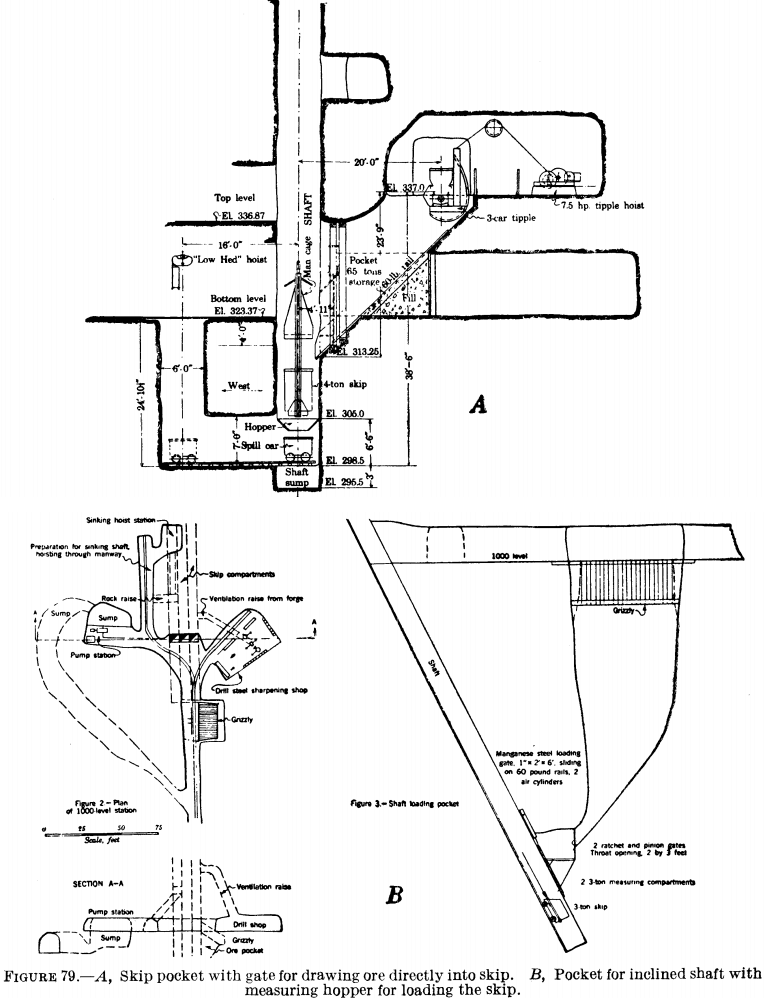
Figure 79, A, shows a loading pocket with the front of the bin nearly flush with the side of the shaft. The ore is drawn directly from the pocket into the skip without the use of a measuring hopper. The haulageway runs parallel to the long dimension of the shaft, and as the cars, which are of the solid-body type, come over the pocket they are dumped by means of a rotary dump. The ore is drawn through vertical, compressed-air-operated, overcut guillotine gates.
Figure 79, A, shows a lay-out for an inclined shaft where the cars are dumped into a large pocket and after dumping are pushed back onto a tail track. The ore is drawn from the pocket through rack- and-pinion, overcut guillotine gates into measuring pockets, each of which holds one skipload of ore.
As previously noted, the use of measuring pockets or hoppers eliminates delays in loading and thus shortens the time of the hoisting cycle. Whereas 25 years ago comparatively few pockets were equipped with these auxiliary measuring hoppers, their use has become almost universal where rapid hoisting is required. The hoppers are filled while the hoist is in motion, and as soon as an empty skip comes to rest under one of them the loader opens the hopper gate, filling the skip. Since the hoppers hold only enough for a skipload, spilling is reduced to a minimum. When the skip is loaded directly from the large pocket, delays may be occasioned by hanging up of the ore back of the gate, and runs of fine material caused by inability to close the gate quickly may overflow the skip.
Skip pockets and measuring hoppers are of varied design, from simple ones such as that shown in figure 79, B, to very elaborate ones. They should be designed to suit the tonnage and nature of the material to be handled, and the general lay-out must conform in individual cases to the position of the haulageway relative to that of the shaft, the available depth below the level, and the nature of the rock and the way it stands. Interference with pump rooms, sumps, and discharge columns must be avoided; underground crusher stations and other factors may further complicate the problem.
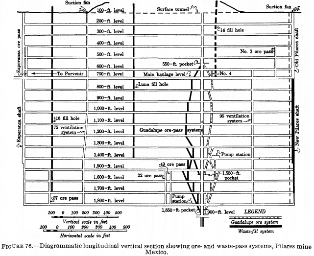
In some mines where the ore breaks large, loading it into skips may be facilitated considerably by installing a primary crusher ahead of the pocket. This practice is common in Ontario and Quebec and not only speeds loading by preparing the ore so that it will run freely but also reduces wear on the pocket and skip linings and breakage of gates. Figure 75, B, shows a general lay-out where a main ore-pass system delivering ore to crusher stations at four separate horizons in the shaft is employed in conjunction with skip pockets and measuring hoppers.
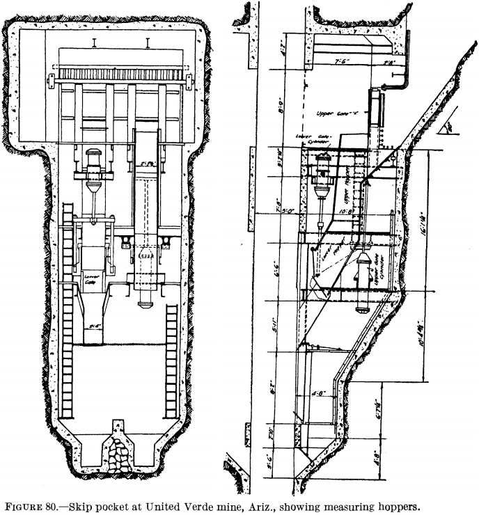
Figure 80 shows a somewhat elaborate installation below a 500-ton main pocket. The main or upper gate is of the vertical sliding undercut plate type and is actuated by a large air cylinder. The ore is drawn through this gate into a measuring hopper equipped with an undercut arc gate actuated by another air cylinder. Below this gate is a short, steep slide or chute that directs the ore into a 112-cubic-foot skip.
It will be noted that the measuring hopper virtually has a bottom discharge. This installation was made at the United Verde mine. The average time required for loading the 112-cubic-foot skip was 7 seconds, and the spill from hoisting 2,000 tons per day was 6 tons. Only one skip loader was required to handle this tonnage.
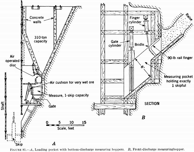
With some very sticky ores it is necessary to have a bottom discharge similar to those shown in figures 80 and 81, A, to prevent the ore from packing in the hopper.
With coarse, dry ore that does not pack, a front discharge such as that shown in figure 81, B, may be satisfactory. In this installation
storage is provided in the raise at the right. The ore breaks in large chunks and the chute is provided with a finger gate. The measuring pocket is discharged by raising the vertical guillotine gate. This arrangement is very compact and requires only a small amount of excavation around the shaft.
The illustrations show only a few of many skip-pocket installations described in Bureau of Mines circulars and in the technical press but serve to indicate the various types in common use. At some mines the measuring pocket is a weigh-hopper, which, when filled, automatically closes the main pocket gate or stops a belt or pan feeder extending from the main pocket to the hopper. The discharge gate of the measuring pocket at some mines is opened automatically when the descending empty skip reaches the loading position, and at others the entire operation is automatic—opening and closing the main
gate, filling the measure, and opening and closing the gate on the measure.
Cost of Stations and Pockets
There are few published data covering the cost of cutting and timbering shaft stations and pockets. Except, perhaps, for the simplest lay-outs, such as those for caging cars, they are not standardized and vary widely as to size, nature of support (whether natural or of timber, steel, or concrete), ground conditions, type of gates and methods of operating them, and types of measuring hoppers and details of their construction and operation.
The excavations may involve raising, drifting, crosscutting, stoping, and sinking, and various methods for removing and disposing of the broken rock may be employed. Broadly speaking, the cost of actual excavation is roughly the same as for similar operations in other mine developments and in stoping, although work in close proximity to the shaft may cost somewhat more owing to the care required in blasting to avoid injury to the shaft. Thus drifting, crosscutting, raising, and sinking costs would approximate those of driving openings of the same size, which have been discussed under “Development.” The cost of enlarging smaller openings to form shaft stations and ore pockets may be roughly the same on a tonnage or yardage basis as for stoping in similar ground, except that support of the ground must be of a permanent nature and therefore may cost considerably more. Thus it may be necessary to install heavy timbers or structural-steel supports and concrete linings or to gunite the walls.
A few data on costs of excavating stations and pockets are given below. At the Sylvanite mine, Kirkland Lake, Ontario, costs of cutting stations only on levels in 1931 were as follows. The rock was syenite and syenite porphyry.

The cost of cutting two stations comprising 8,196 cubic feet of excavation at the Vipond mine, Timmins, Ontario, was $2,885.49, or $0.35 per cubic foot. The rock was a basaltic schist or greenstone.
Costs of level stations, pump rooms, ore pockets, and skip-loading stations and equipment at Matahambre (Cuba) No. 2 shaft in 1930 were as follows:

