When mixed with common cast steel in quantities ranging from 11 to 13½ per cent. and properly treated, manganese increases the ductility of the metal and adds greatly to its toughness and resistance to abrasive action, which properties comprise the distinctive characteristics that make manganese steel so valuable for many purposes at the present time.
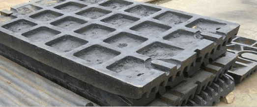
Manganese steel has been manufactured for years. It was first made in a small way in England and subsequently produced in the United States. In the early days of the industry it was impracticable to make manganese castings weighing over a few thousand pounds, but at present crusher heads, rolling-mill pinions, and similar castings weighing up to 30,000 lb. each are produced, and it does not appear that the limit of weight has been reached by a considerable margin.
Manganese steel is similar in analysis to ordinary first-class converter metal except that it is high in carbon and contains from 11 to 13½ per cent, of manganese. From one standpoint manganese steel is similar to malleable iron in that the casting as it comes out of the sand is hard and brittle and must be made ductile by a heat-treating process. The heat treatment is an essential part of the process of making manganese-steel castings and must be properly carried out to secure satisfactory results. The necessity for heat treatment limits the thickness of sections which may be made of manganese steel. Originally the annealing depth was comparatively small, but researches carried on during the past few years have resulted in an increase in the thickness of section up to 5½ in., which it is possible to treat successfully. Large castings are cored out to a minimum thickness of 5½ in., thus not only eliminating some of the internal stresses which are invariably set up in a very thick casting, but also reducing the weight and inertia of the piece, an important consideration if the casting is to be a moving part in a machine. At the same time, the thickness of 5½ in. is sufficient to permit the use of manganese steel for the heaviest classes of machinery.
Before taking up the application of manganese-steel castings to machinery used in the mining industry, a few details covering the chemical and physical characteristics as well as the micro-structure of this material will be presented. Chemically, cast manganese steel has about the following composition:

The following results are an average of 19 physical tests of manganese steel: Elastic limit, 53,396 lb. per square inch; tensile strength, 108,460 lb. per square inch; elongation in 2 in., 33.71 per cent.; reduction of area, 38.56 per cent.
The distinctive characteristics of manganese steel are clearly indicated by the microscope. As is well known, manganese is present in all ordinary steel, but the metal does not become austenitic until about 6 per cent, manganese and 0.80 per cent carbon are introduced. Commercial austenitic manganese steel generally contains from 11 to 13.5 per cent, manganese and from 1.00 to 1.30 per cent, carbon.
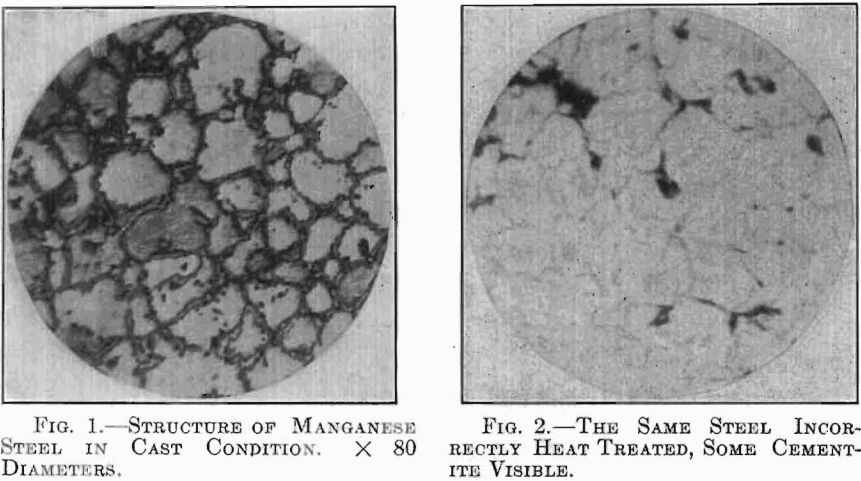
In the cast state, manganese steel is composed principally of austenite and free cementite, austenite being a solution of iron, manganese, and the carbide of iron and manganese, while free cementite is composed of the carbides of iron and manganese which remain undissolved. Free cementite is hard and brittle, therefore manganese steel is also brittle in the cast condition. We thus have a metallographic explanation of the chief characteristics of manganese steel. Microscopic examination reveals the fact that if the steel is heated to a proper temperature and quenched in water, the free cementite is dissolved and the whole becomes austenite.
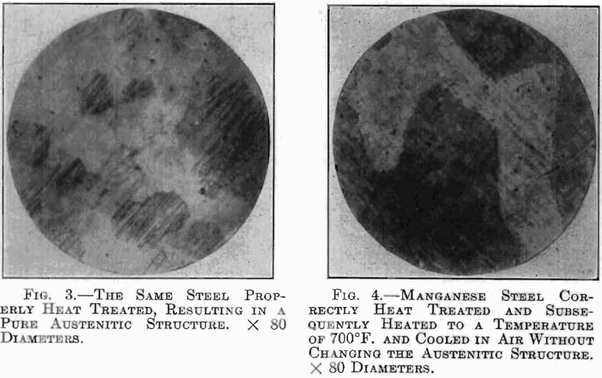
The accompanying microphotographs, Figs. 1 to 5, show the structures of manganese steel as cast and after treatment. Fig. 1 shows the structure of manganese steel in the cast condition. Fig. 2 shows the structure of the same steel heated to a temperature of 1,750°F. and quenched in water. The heat treatment was not correct, and although much of the free cementite has disappeared, some of it still remains in chunks as shown by the dark spots. Fig. 3 shows the structure of the same steel heated to a temperature of 1,800°F. and quenched in water. In this case the heat treatment is correct and all of the free cementite has disappeared, leaving a purely austenitic structure.
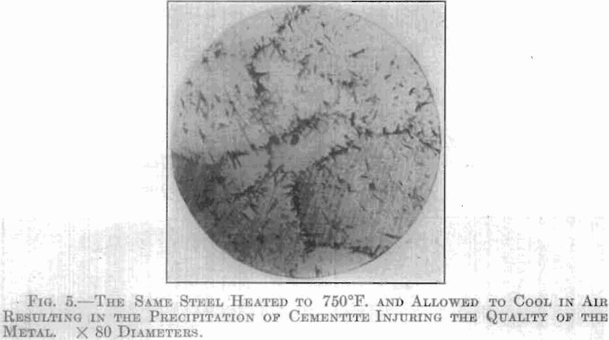
The effect of subsequent heating and cooling in air is shown in Figs. 4 and 5. Fig. 4 shows the structure of a manganese steel which had received a proper heat treatment and was afterward heated to a
temperature of 700°F. and allowed to cool in air. The structure is exactly similar to that shown in Fig. 3; the steel, therefore, has not been injured. Fig. 5 shows the structure of the same steel heated to
a temperature of 750°F. and allowed to cool in air. A heavy separation of cementite, shown by the needle-like particles, is clearly visible. This proves that heating the steel to over 700°F. destroys the purely austenitic structure, seriously injuring the quality of the metal. It is therefore imperative that manganese steel should not be heated to a temperature exceeding 700°F. after being heat treated. The experiments on which the foregoing micro-photographs are based were carried out with the aid of an electric furnace equipped with a pyrometer.
By the Brinell test manganese steel toughened or untoughened shows the moderate average hardness number of about 200. The extreme outer surface of the treated steel shows a slightly lower number than at a depth of about 1/8 in., from which point the number remains constant to the core of the casting. The lowering of the hardness number at the surface is due to the oxidization of the carbon during the heat treatment.
The qualities of manganese steel have led to its adoption extensively for the vital parts of heavy-duty machinery, particularly parts subjected
to unusual wear, shock, etc. Manganese-steel castings are used today in the construction of wearing parts for the following kinds of machinery: Rock and ore crushers, coal breakers, ball mills, tube mills, pulverizers, comminutors, clay mills, traveling cranes, gold dredges, harbor dredges, steam shovels, ditching machines, pig-casting machines, pug mills, coke machines, stead-rolling machinery, stamp mills, cable haulage systems, screening apparatus, centrifugal sand pumps, grab buckets, concrete mixers, etc. Manganese steel is also extensively used in the manufacture of steam and electric railway track work, elevator buckets, gears, pinions, mine and skip car wheels, and for numerous other purposes.
The use of manganese steel for tube-mill liners is a recent development which is of special interest at this time because of the curtailment in the supply of lining materials previously used, by reason of the war abroad. Until the introduction of manganese-steel liners, tube mills were lined almost exclusively with silex blocks imported from Europe, principally from Denmark. The pebbles used in tube mills also have been imported, chiefly from France and Denmark. The manganese-steel liners have been developed to the point where they form a satisfactory substitute for silex blocks, and experiments are now being conducted on the use of 2- and 3-in. diameter manganese-steel balls in place of imported pebbles. A manganese-steel tube-mill liner known as the Komata, developed by E. C. Brown, is now used with good results.
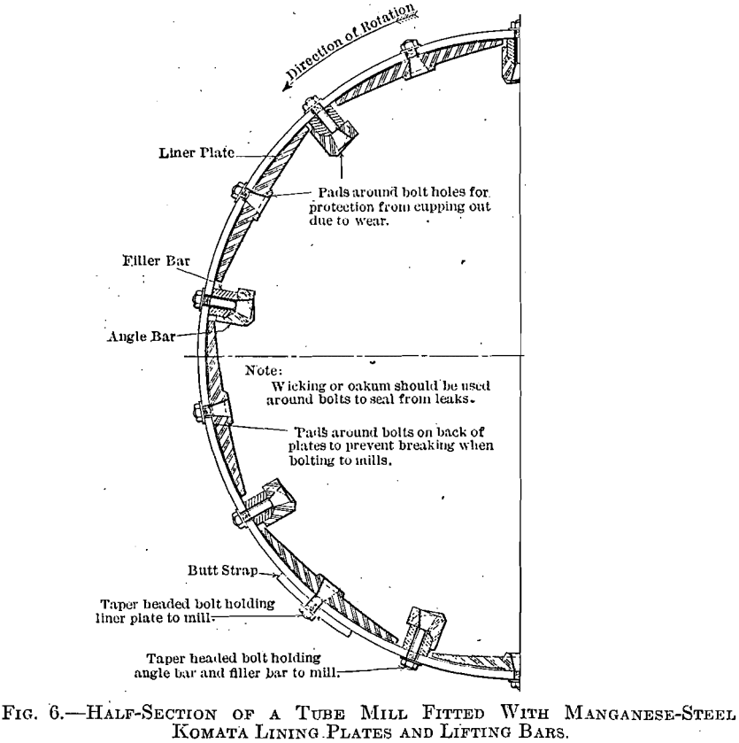
As indicated in Fig. 6, it consists simply of a series of plates and lifting bars securely attached to the shell of the mill by square-headed taper bolts, drawn up from the outside, so that the plates are held in place even when worn extremely thin. The lifting bars perform an important function, their action being similar to the bars installed in Bradford coal breakers. The bars carry the pebbles up to a point considerably beyond the centerline of the mill, causing an almost perfect cascading action. For this reason the pebbles maintain a spherical shape and the great commotion and rolling action of the pebbles produces an effective grinding action. The pebbles do not slip on the liners, with the result that the life of the plates is prolonged and the tendency of pebbles to become flat is prevented.
The lifting bars are invariably made of manganese steel because of the great wear to which they are subjected. The lining plates are preferably made of the same material, but if local circumstances warrant, they can also be cast of less expensive semi-steel or white iron at local foundries. To prevent the liner from cupping around the bolt holes, raised bosses are placed on the castings around each hole.
In operation the pulp soon gets behind the plates and forms a cushion or backing. The ribs, or lifting bars, are spaced from 18 to 20 in. apart according to the diameter of the mill. The filler bars which are placed underneath the lifting bars are not exposed to wear and therefore are made of soft cast iron. The joints in the bars are staggered with the joints of the liner plates to prevent the formation of grooves or channels in which the pulp might travel and wear the shell of the mill.
When a manganese-steel liner is employed, the speed of the mill has an important influence on the results obtained. The correct speed can be derived from the following formula:
Revolutions per minute = 183 ÷ √D
where D is the diameter of the mill in meters.
To secure satisfactory results, the pebble load should be about 3 to 5 in. below the centerline of the mill, depending on the diameter. When grinding ordinary coarsely crushed battery pulp, the new pebbles fed into the mill should not exceed 2½ in. or, in any case, 3 in. in diameter.
For the year ended June 30, 1914, one of the largest milling companies in Nevada reported the following consumption of lining material: Manganese-steel lifting bars, 16,633 lb.; semi-steel liner plates, 49,916 lb. During this period, 341,354 tons of ore were ground, comprising the discharge of 12 batteries equipped with 3-mesh screens, together with the discharge from eight batteries passed through Chilean mills equipped with 16-mesh screens, both products being passed through Dorr classifiers before the sands were fed to six 5 by 22 ft. tube mills. The actual sliming done by the tube mills was estimated at 100 tons per day per mill, 80 per cent, of the product passing through a 200-mesh screen. The pebble consumption for a similar period was 1,647,524 lb.
At this plant a set of manganese-steel lifting bars lasts about 14 months and a set of semi-steel liner plates, which are 1 11/16 in. thick at the center, tapering to 11/16 in. at the edges, lasts about 23 months.
In some of the mills manganese-steel liner plates also were used. They were in service 29 months and when removed weighed less than 30 lb. each. These plates were 1 1/8 in. thick at the center, tapering to 3/8 in. in thickness at the edge.
The consumption of metal and pebbles per ton of material ground, according to the figures given previously, was as follows:

In the mills in which the foregoing tests were made, it is not customary to renew the whole liner at once, but to remove worn-out pieces from time to time as necessity demands.
Some interesting tests of manganese-steel liners have also been made on a Schmidt-Davidson type mill in operation in New Zealand. This mill is 4 ft. 6 in. in diameter and is run at 23 r.p.m., which was found, to be the most effective speed when using lifting bars. The liners in this case were of hard, white cast iron made at a local foundry. When new, the liners were 1 in. thick in the center, tapering to 3/8 in. at the edges, the lining weighing 5,940 lb. There were 10 rows of ribs in the mill with an aggregate weight of 2,347 lb. The liners were used for 75½ weeks and the angle bars for 60½ weeks before they required replacing. From 187 to 232 tons of ore were passed through the mill daily, these figures, including the coarse sand which was returned to the mill as many times as necessary. The stamp delivered an average of 76 tons of ore to the mill daily. The pebbles were from 1½ to 2½ in. in diameter.
During the last six months of the run, the fineness of grinding was increased and for this reason the quantity of ore fed to the mill from the stamps was reduced to 55 tons per day, exclusive of returns. The fineness of the ore before and after grinding, when crushing this tonnage, averaged as follows:
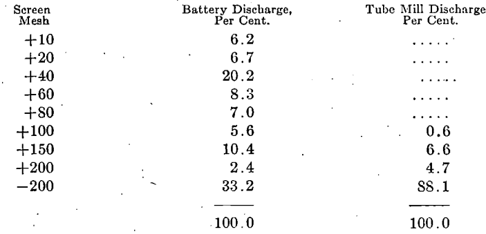
The pulp passing through the tube mill varied between 1 and 1.4 parts of moisture to 1 of ore by weight. The adoption of this special form of liner is said to have reduced the consumption of pebbles by 70 per cent., the liner cost having been cut 37 per cent.
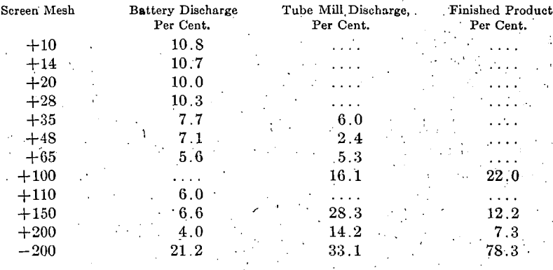
A company at Tonopah, Nev., is operating two 5 by 18 ft. tube mills fitted with Komata linings. These mills run at 24.4 r.p.m. and they require 98.67 hp., or 46.335 hp. per mill. The mills are fed with the discharge from stamps which are equipped chiefly with 6-mesh screens, a few batteries being provided with 4-mesh screens. The feed contains 38 per cent, moisture. With a pebble consumption of approximately 4 lb. per ton of ore ground, the results are as follows:
Manganese steel has been found particularly suitable for dredge buckets in the gold-dredging districts of Montana, California and elsewhere, the life of the manganese-steel buckets being reckoned by years instead of months. The buckets usually are cast solid and the lips riveted in place; they range from 600 to 5,000 lb. in weight each, the average being about 2,200 lb. A number of buckets of this type have, been in service since September, 1909, and judging from present indications their total life will be from 10 to 12 years.
Usually placer dredge buckets are removed from service because the metal underneath the back eye wears away. In some cases the buckets are worn entirely through to the bushing at this point before they are taken from the line. The metal underneath the back eye ranges from 1½ to 3 in. in thickness, depending on the size of the bucket. Some observations were recently made of the wear on 50 manganese-steel buckets placed, in service on a dredge in Montana , in December, 1911. These buckets have a capacity of 9 cu. ft. each. When new; the metal underneath the back eye had an average thickness of 2½ in. After having been in service for three years, actual running time, the buckets were again measured and the metal under the back eye was found to have been worn to an average thickness of 1 7/8 in. In other words, about 5/8 in. of metal was worn away. This means that 1¼ in. of metal are still available for wear, assuming that the buckets are worn out when the thickness is reduced to 5/8-in. Since the wear has amounted to 5/24 in. per year, the estimated total life of the buckets is nine years.
Another set of measurements was made recently on a line of 86 5-cu. ft. dredge buckets which have been in service in Colorado for 32 months, actual running time, covering the period from March, 1911, to Aug. 5, 1915. These buckets which when new had a thickness of 2 1/8 in. underneath the back eye showed an average wear for the period of 3/8 in. Assuming that the 5-cu. ft. manganese-steel buckets would be discarded when but 5/8 in. of metal is left underneath the back eye, the estimated life is 10½ years running time. It is estimated that the average life of a carbon-steel bucket line on this particular dredge would not exceed 30 months:
Most dredge buckets now made are of the two-piece type, the bottom and hood each being cast integrally. With this design of bucket, leakage is avoided and there is no danger of loss of valuable material through the rivet holes while the; bucket, is carrying its load from pond to the upper tumbler. A short, lip can be used on the two-piece buckets and comparatively few rivets are required.
The tumblers on gold dredges also are frequently made of cast manganese steel, some of them weighing 24,578 lb. The tumbler is simple in construction, consisting of nothing more than spool cast in one piece, the bore being finished by grinding. Renewable wearing plates are eliminated on both the inside and outside of the flanges and on the barrel. Although the round tumbler is used successfully with the ordinary type of bucket, it is considered preferable to widen the bottom of the bucket somewhat when a tumbler of this type is employed. This usually is accomplished by placing a flange-along the outside of the bucket at the bottom between the front and rear eyes.
Screen plates are also being successfully made from manganese steel. When used, in connection with gold dredges, the hole may be either ½ in. in diameter, tapering to 5/8 in., on the outside, .or 5/8 in., in diameter, tapering to ¾ in. on the outside. In order to overcome the difficulties of casting round holes in manganese steel, some plates have been designed with rectangular slots about ½ in; or 5/8 in. wide on the inside, tapering to 5/8 or ¾ in. on the outside, the slots being 1¼ in. long and set diagonally. Elevator buckets of the same thickness as malleable iron buckets are now made of manganese steel, the latter giving six times the service of the malleable iron.
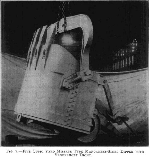
The application of manganese steel to steam-shovel dippers was one of the first problems attacked by the manufacturers of this material in this country, the wear in this service being particularly severe. A dipper known as the Missabe type is made entirely of manganese steel. Its body consists of but two castings, the front and back halves, which give maximum stiffness and rigidity. This design permits the construction of a large dipper with only a few rivets. The bail brackets are set at an angle conforming to the line of pull on the bail. They are butted against shoulders or offsets which are formed integrally with the sides of the front castings and are riveted to the front half of the dipper, the joints between the front and back halves being placed at the rear of the brackets, thus throwing all the digging strains on the front casting, and relieving the rivets at the joints from shearing stresses. The teeth, which are easily renewable, are of cast manganese steel.
Dippers of the Missabe type of 10-cu. yd. capacity, which are believed to be the largest manganese-steel dippers ever made, were used on dredges working in the Culebra Cut, Panama Canal. The weight of the empty dipper is 37,600 lb. and its overall dimensions are 9 by 9 by 10½ ft. The lips are 3¼ in. thick and the fronts are the same thickness underneath the teeth. Between the teeth the fronts are 1½ in. thick, the thickness at the bottom band being 3¼ in. The backs are 1¼ in, thick, except at the bottom where the thickness is increased to 3¼ in.
Another improved dipper front is known as the “ Vanderhoef, ” in which the front and the dipper-tooth bases are cast integrally. The renewable points are substantially designed and are of the reversible type. Among the advantages of this design may be mentioned the elimination of rivets, correct digging angle, increased room inside the dipper, due to the position of the base portions, great strength coupled with rigidity of the entire front, and economy in repairs and renewals.
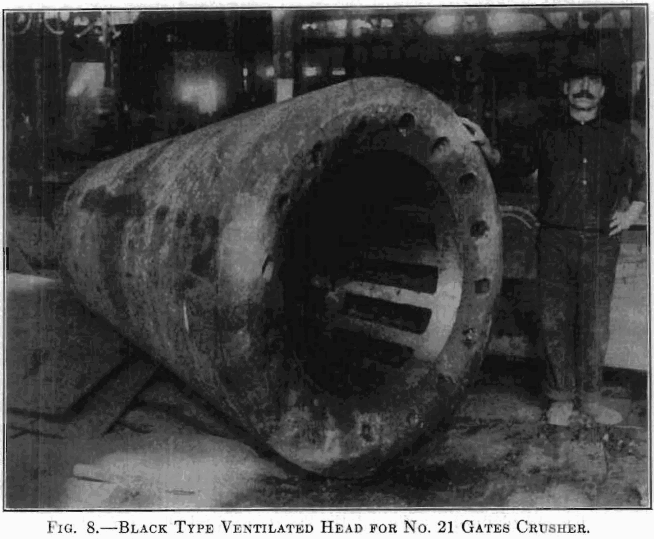
This casting weighs 21,360 lb. As shown in the illustration, it is provided with a series of vertical flues or cores running from top to bottom which permit a circulation of air between the wearing surface and the shaft. This tends to prevent the transmission, from the wearing surface to the shaft, of the heat incident to crushing. As compared with a solid head, the weight is reduced from 20 to 30 per cent.
Manganese steel although not suitable for railway car wheels on account of its comparative softness, has been found satisfactory for mine and skip-car and crane wheels. For crane wheels carrying heavy rolling loads, manganese: steel has been, found particularly satisfactory, Manganese-steel-crane wheels are in service, today carrying loads of 90,000. lb. each, although 30,000 lb: has always been considered the limit of safe working load for chilled-iron wheels. A microscopic examination, of a manganese-steel wheel under load will show a flat spot instead of a line, contact as in the case of hard metal wheels manganese steel under these conditions is springy and recoils as the load is released. The wheels also exhibit strong resistance to flange wear. This feature is worthy of consideration in view of the fact that derailments on curves are usually caused, by the flanges having worn to, the angle of least frictional resistance, allowing the inherent straight, line force to push the wheel flange over the rail.
Where the loads are heavy, manganese steel is now being extensively employed for gears. For the past, two years manganese-steel spur-gears have been made with the teeth ground mechanically true, up to 44-in. pitch diameter with a 10 in. width of face. Many ordinary steel gears are cut with a range cutter which does not leave the rolling contact theoretically correct, whereas in grinding manganese-steel- gears, a trimming arrangement is placed on the grinder for the purpose of dressing the emery wheel which shapes the tooth to the proper contour.
After two years continuous service, the wear on a set of heavy, high-speed manganese-steel nest gears was recently measured. These gears had a 10-in. face and when new the thickness of the tooth at the pitch line was 0.684 in. At the conclusion of the two-year period, the tooth measured 0.601 in., the wear being 0.083 in. These gears are still in service after having more than earned their original cost, and barring accident they will be good for many years to come.
Manganese steel is now employed extensively in rolling-mill machinery; it has been found particularly suitable for pinions on heavy roughing and blooming mills. Other parts around steel mills now being made of manganese-steel are pipe-drawing balls, chafing plates, sprockets, cams, draw chains, unloader chains, conveyor chains, buckets, screens, pulverizer hammers, dry and wet pan parts, crusher castings, coupling, boxes, spindles, and backing rolls.
For the production, of manganese-steel castings the shop practice, is fundamentally similar to that of an ordinary steel foundry, but a number of factors not vital in, ordinary work must be considered. Among other points, the shrinkage is 5/16 in. per foot as against 3/16 to ¼ in. for ordinary steel. For this reason the founders frequently prefer to make their own patterns from drawings supplied by, their customers. Where patterns are furnished, sometimes they have to be modified or rebuilt.
The distribution of the metal in the casting is also important, since the heat treatment and cooling produce stresses which must be taken care of. At times it is necessary to add metal to a casting temporarily to withstand shrinkage strains, such additions of metal being removed in the machine shop. Manganese steel, being comparatively expensive, must be used economically, for which reason designs or patterns occasionally have to be altered.
In making manganese steel, side-blow converters are commonly employed and the 80 per cent, ferromanganese with which the steel is alloyed is melted in separate crucible furnaces. The melted alloy is placed in the bottom of the ladle and the converter metal is poured in on the top.
Manganese acts as a strong scavenger, removing the gases and impurities from the metal, leaving it condensed and homogeneous. Before the molds are poured, the ladles are allowed to stand for a time to permit the alloy to perform its function, after which the accumulation of slag is removed.
The annealing process is particularly important. The temperatures and the time the work is allowed to remain in the furnace vary considerably, depending upon the nature of the piece; the temperature ranges from 1,600 to 2,200°F. and the time of annealing from 4 to 24 hr.
The gates and risers of castings can be broken off as in malleable foundries. The cores are removed with pneumatic drills and the exterior surfaces are cleaned and trimmed by grinding.
Castings which are to be accurate are finished in the machine shop by grinding, much of the work requiring special grinding equipment. Holes more than 1¼ in. in diameter are cored out of the casting and ground to size. When it is necessary to drill smaller holes or to cut threads, soft steel or wrought-iron inserts are set in the molds at the desired points, like chaplets, and the metal is cast around them. Except in small holes, inserts or bushings are not necessary where keyways are cut, since these can now be ground successfully. Sometimes bushings are set in the hubs of wheels to be machined by ordinary methods.
The foreman continually exercises his judgment as to the wheels and cuts to be employed; coarse wheels and heavy cuts are used for removing stock rapidly, though it is never accomplished as easily as would be the case were it possible to use ordinary cutting tools.
A complete manganese-steel castings plant, therefore, includes a steel foundry with special equipment for melting ferromanganese and annealing castings, a pattern shop, and a machine shop equipped with heavy-duty standard and special grinding apparatus.
