Transporting minerals as a slurry is an efficient means of transportation and is done during many mineral beneficiation processes. However, the movement of slurries can cause significant wear to the slurry-handling equipment, especially in places where the flow changes direction. Wear caused by slurries is an economic concern of industry. Pumps, elbows, tee junctions, and hydrocyclones are component parts of slurry transport systems that are exposed to severe wear. In a slurry, abrasive erosion is produced by the solid particles, and corrosion may be produced by the liquid; the two are frequently synergistic. Reliable experimental wear data are needed to aid in the design of slurry transport equipment.
Types of slurry wear tests reported in the literature include slurry pot, pipeline, and jet impingement. All of these involve low-stress, two-body abrasive wear. Many variations of a slurry pot test have been devised. Jackson used a rotating wire, Tsai used two rotating metal tubes, and Bess used a rotating disk as specimens in baffled pots containing abrasive slurries. These slurry pot tests relied on experimental reproducibility because only one type of specimen was used in any one test. In addition, the impingment velocity was based on the assumption that baffles in the pot held the slurry stationary. Postlethwaite, Hocke and Wilkinson, and Elkholy used closed-loop slurry pipeline test systems. Postlethwaite used rectangular specimens that were flush with the inside wall of the pipeline, and Hocke used rectangular specimens with a slurry jet impingement tester. All of the above-mentioned slurry wear tests have the problems of abrasive particle degradation and slurry contamination by wear debris. These problems are inherent in tests that re-circulate the slurry for prolonged times. The low-angle slurry pot test devised by the Bureau is normally operated in a flowthrough mode that essentially eliminates the problems of particle degradation and slurry contamination.
Slurry Pot Equipment and Specimens
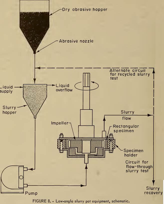
The Bureau’s slurry test apparatus is a slurry pot consisting of an impeller that rotates the slurry past an array of specimens located around the inside of the pot. Thus, the impingement angle is low or nearly tangential. A schematic of the equipment is shown in figure 8. The slurry pot consists of a plastic ring with 16 sides that form a hexadecagon to hold specimens. This central section is bolted to a stainless steel top and bottom and is sealed with 0-rings. In order to avoid galvanic effects between unlike specimens, eight specimens are alternated with eight plastic inserts around the inside of the plastic ring. Both the specimens and plastic inserts are 24 by 32 mm and 10 mm thick. The plastic inserts are made of ultrahigh-molecular-weight polyethelene, which has proven very wear resistant. The ends of the specimens are beveled to fit adjacently inside the plastic ring. The test surface of the specimen is surface-ground and polished through 400-grit abrasive before each test.
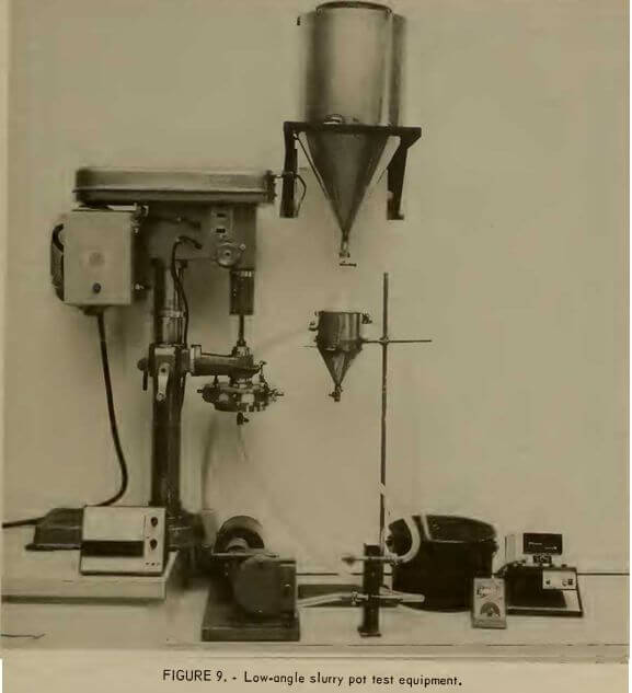
The impeller is made from a commercial helical gear made of hardened steel that rotates to move the slurry past the stationary specimens. Dry sand is fed through a nozzle to a slurry hopper where the sand is mixed with the liquid. In tests conducted with this flow through system, typically, tapwater is fed to the system at a rate of 4.34 L/min and the sand is fed at 88 g/min, which results in a mean retention time for the sand in the slurry pot of only 2 s. The slurry discharges to a settling basin where the solids settle and the water flows to a drain. A modified drill press supports the slurry pot and drives the helical gear. A magnetic pickup provides a means to electronically measure the impeller tip speed, which can be varied from 1.3 to 22.4 m/s by changing the belt system in the drill press. The temperature of the slurry is monitored at the discharge of the slurry pot. The equipment is illustrated in figure 9.
Alternatively, the slurry can be recirculated by shifting the slurry discharge back into the slurry hopper, as shown in figure 8. This alternate mode can be used to study the changes in particle


shape and roughness and their effect on wear rates. Tests such as these also can be used to characterize wear mechanisms.
Slurry Pot Procedure
Specimens are prepared for testing by cleaning, drying, and weighing to the nearest 0.1 mg. Up to eight specimens along with the plastic inserts are placed inside the plastic center ring. Replaceable inserts above and below the specimens ensure that the specimens are electrically insulated from the stainless steel top and bottom sections.
The mass flow rates of the dry abrasive solids and the solution are each adjusted prior to the test to provide the desired percent solids and slurry flow rate. After the solution is pumped through the system for a few seconds, the helical gear and sand flow are started, and the time is noted. After a predetermined test time, the slurry pump and helical gear are stopped, and the samples are removed, cleaned, dried, and weighed. The specimens are put back into the slurry pot, and the test is repeated several times. The volume losses are calculated and recorded as a function of time. Curves of time versus volume loss are then compared with data obtained with standard AISI A514 steel specimens. The test procedure in the recirculating mode is essentially the same, except the percent solids is determined by the initial mass of solids and solution put into the system.
One of the attributes of the flowthrough system is that the temperature of the slurry is nearly constant and is determined by the temperature of the liquid supply. When recycled slurry is used, a means of heat exchange at the slurry hopper is required to prevent overheating of the system.
Specimens can be reused after regrinding and repolishing the wear surface and regrinding one beveled edge. Plastic inserts are placed behind the reground specimens in order to maintain the same clearance between the rotating gear and the specimen surface. This assures the same geometry inside the pot and gives a constant exposed area of wear surface. The size of the specimens allows two to be made from each previously worn specimen from dry-sand, rubber-wheel abrasive wear tests or jaw crusher tests.
Slurry Pot Results
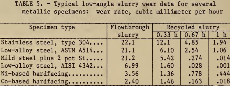
Typical results of wear testing with the low-angle slurry pot are presented in table 5 for both flowthrough and recycled slurry tests. Results of the flowthrough tests showed that the wear rate is constant with respect to time. In contrast, conventional slurry tests that use a recycled slurry give decreasing wear rates with time. In addition, table 5 shows that lower wear rates were obtained with recycled silica sand. The lower wear rates result from the rounding of the slurry particles during the test. The ranking of specimens with

Note.—Water with 2-pct silica sand (minus 50 plus 70 mesh) 17° C, 15.7 m/s
respect to wear rate also can change during a recycled slurry test. For example, after 1 h, the fifth specimen had a greater wear rate than the fourth specimen.
Related: Drill Press for Metal
