This is in part a review paper, indicating the various steps that have been taken in developing hindered-settling apparatus, some of the standard data that have been obtained, and some of the conclusions one is led to as to the effect of it in improving concentrating-methods and machinery, and in part it brings in some unpublished work.
CAUSES OF LOSS IN ORE—CONCENTRATION:
In making a study of the separation of valuable minerals from the waste gangue, particularly by water concentrators, it is necessary to define, first of all, what are the causes of loss that are likely to interfere with the concentration. Having made this definition, we can then study to see in what way the machines make their losses, and plan remedies for them in an intelligent way. Losses may be stated to occur as included grains, as flat or long grains, as fine free mineral, and as absolute slime. We will take these up one by one, as follows:
Included Grains, Fig. 1 shows by a set of diagrams how included grains may occur : first, where the heavy mineral grains attached to the quartz are of large size; secondly, where they are of small size; and thirdly, where very fine particles of heavy mineral are included in the quartz. We have to decide in regard to included grains whether they are rich enough to go direct to the furnace, or poor enough to throw away, or whether they lie between these two points and require recrushing as the only means of severing the values from the waste. This last case is the only one requiring special treatment at our hands. We will therefore consider that next.
It will be noted that the valuable mineral is in coarse, medium, or fine grains, and that in order to sever these from the quartz, so that the concentrator can save them, we have to decide how fine the recrushing shall be. The exact size to which recrushing should be carried has to be determined in each case, and may be stated to be that size which liberates the maximum of the valuable mineral while making the minimum of slime. Where valuable mineral severs easily from the gangue, if it is brought down to twice the size of the grains of the valuable mineral, then they may be nearly all severed. If, however, the grains of valuable mineral do not sever easily from the gangue, then it may be necessary to break down to half their size in order to liberate a sufficient number of them completely from the gangue, so that the concentrating-machines
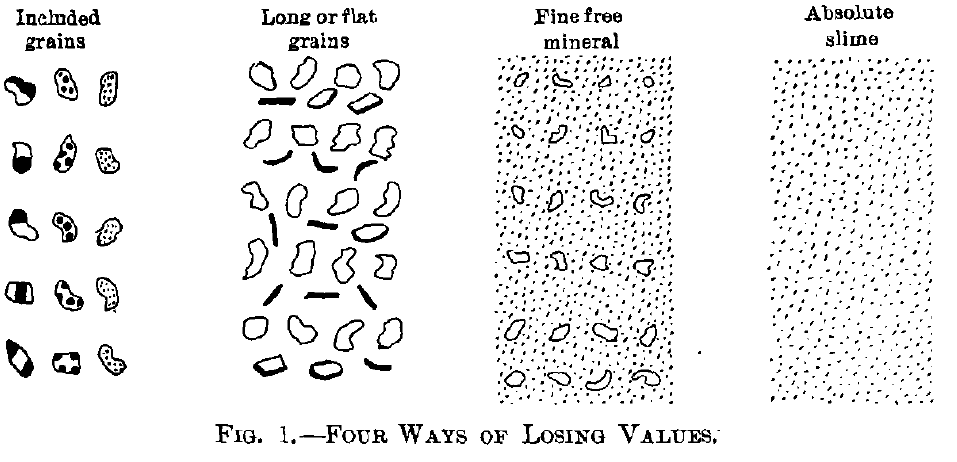
can satisfactorily do their work. It follows from this that where the valuable mineral is in large grains coarse crushing is suitable; where it is in medium-sized grains, crushing to medium sizes would be required; and where the grains are very fine, extremely fine crushing would be required.
Flat Grains and Long Grains.— Of these two, flat grains seem to be much harder to save than the long grains, as the flat grains have such a large surface in comparison with their weight that they settle slowly in water and therefore are not placed where their gravity would seem to indicate that they should be. There sterns no way of saving flat grains other than to recrush them and treat them just as if they were included grains. The size of recrushing here will have to be determined by the same consideration as was shown under Included Grains. Graphite, being lighter than quartz, is an exception to the above rule; its hat form helps save it.
Fine Free Mineral.—Products containing fine free mineral, see Fig. 1, are made by jigs and Wilfley tables which have a mixed feed or a feed consisting of the finest products of classifiers; the tailings of vanners treating the ordinary stamp-mill pulp also contain fine free mineral. In my opinion, these three products, namely, jig-tailings, Wilfley-tailings, and vanner-tailings, furnish the ripest field for improvement in milling. The object of this paper is to set forth the methods of saving this fine free mineral.
Absolute Slime.—This is the title that has been given to us by David Cole, of the Cananea Copper Co., and by it he means the grains of fine free mineral which are so fine that they cannot be settled in a reasonable commercial time. These grains cannot be handled, therefore, by settling. They can be handled to only an imperfect degree by the round table or by any of the film sizing-machines. Perhaps the canvas table is the most successful, and we may say that it is possible that some of the flotation-processes may succeed in saving this class of grain. The matter, in my belief, is still unsettled as to whether they can be saved by any means or not. The Anaconda method of allowing them to go out in a settling-pond, where the bulk of them settle in sufficient time to the bottom of the pond, is one method of handling this product, but owing to the low percentage of values and the large quantity of gangue, it cannot be said to be a satisfactory solution of the problem.
TYPICAL FLOWSHEET:
Let us take up a general flowsheet containing the chief machines used in concentrating, placing them in logical order, and briefly discuss the position of each, see Fig. 2.
The grizzly and the breaker, let us assume, have brought the material to 25 mm., or 1 in., in size, and have fed it to the mill- bin. The feeder next sends it to a trommel with 8-mm. holes. The oversize of this trommel is fed to the bull-jig, which therefore treats 25-mm, to 8-mm.material,yielding concentrates and middlings, or included grains requiring recrushing. The undersize of the trommel is fed to the next trommel, with holes 2.5 mm. in size. The oversize of this goes to Hancock jig which delivers concentrates, middlings for recrushing or to go back over the jig, and tailings either for waste or for recrushing, according to the richness and value of the ore. The undersize of this 2.5-mm, screen goes to a classifier and the coarsest two sizes go to jigs, which yield concentrates, and may yield tailings as waste and middlings for recrushing, or may yield only middlings for recrushing. The remaining four products from the classifier go to Wilfley tables and yield con-
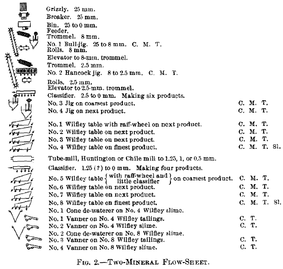
centrates, middlings, and tailings. Where Wilfley tables are fed with the products of a good classifier, and are engaged in making a two-mineral separation, the use of a raff-wheel for returning the middlings to the table is not only a safe procedure, but wise, as the middlings form a very small product and one that can be perfectly separated by the table. Any middlings made by the two jigs or by the coarsest Wilfley tables which contain a large share of included grains, and therefore need recrushing, may be broken by Chile mill, Huntington mill, or tube-mill down to 1.25 mm., or even to 0.25 mm., in diameter, according to the size to which the included grains need to be broken. The pulp from this regrinding must go to another classifier, followed by Wilfley tables, and the final winding up at the fine end can be made by sending the tailings of the finest Wilfley tables of both classifiers to a Callow screen, the oversize of which is clean gangue and the undersize makes a very perfect feed for the smooth-belt vanner; the slime from the finest Wilfley tables of both classifiers can be carried to a Callow cone and be finished up on vanners or other suitable machines. The tailings of these last vanners treating the fine slime will be the worst, and, in fact, the only unsatisfactory, product that will go out from such a mill. I will next take up the investigations that have been made and will refer to four investigations of the separation of sands by the free-settling method.
Free-Settling Tests:
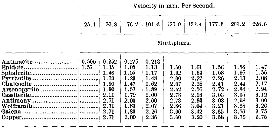
In Close Sizing Before Jigging, using a tube 9 ft. long and about 2 in. in diameter, dropping about 50 grains together, free-settling velocities were carefully determined. Tables I. and II. give, for grains ranging from 1.84 mm. to 0.106 mm. in diameter, the ratios of diameters for grains of quartz and galena when they settle at the same rate.
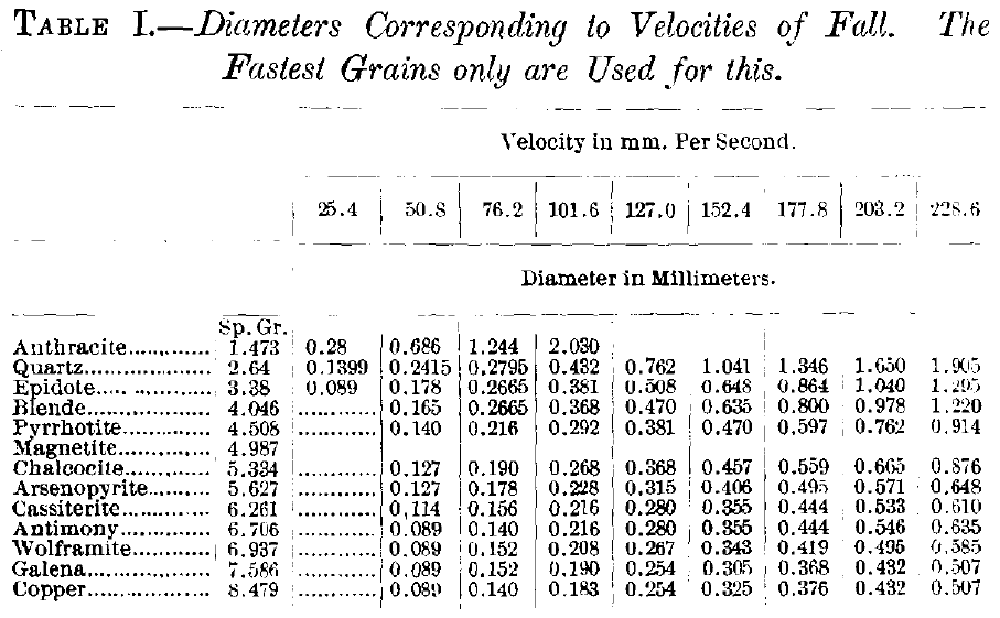
Table II. Free-Settling Factors or Multipliers for obtaining the Diameters of Quartz which will be Equal-Settling with the Mineral Specified when Settling Freely in Ample Water. Using Fastest Grains only.
In the paper, Velocity of Galena and Quartz Falling in Water very complete figures of free-settling velocities of quartz and galena are given, ranging from 11.93 mm. in diameter to 0.00152 mm. in diameter, and these figures are the averages of 100 observations each.
In these tests the larger grains were dropped one at a time 2,800 mm. in a tube 8 in. in diameter, the intermediate grains were dropped 1,000 mm. in a tube 2.87 in. in diameter, and the smaller grains were settled 500 mm. in a decanting-tube (Bardwell’s tube) 500 mm. high and 1.58 in. in diameter. While the ratios are somewhat different at the large end and also at the small end of the table, we find that the diameters of quartz grains from 2 to 0.5 mm. are about 3.0 to 3.5 times the diameters of the galena grains that settle at the same rate under free-settling conditions.
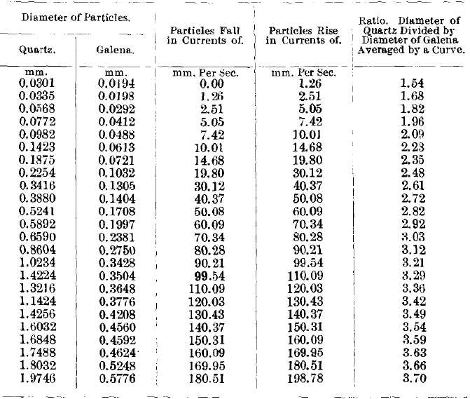
In the paper, Sorting Before Sizing: mixed quartz and galena grains were fed to a glass spitzlutte with sorting-tube 24 in. high and 7/8 in. in diameter. The heavy grains of quartz and galena that were drawn off below were caught in the little bulb placed there to receive them; the lighter grains which could not settle rose and went into the overflow. By using a series of currents starting with the strongest, rising 198.78 mm. a second, and ending with the weakest, 1.26 mm. a second, the overflow of a stronger current each time was fed to the spitzlutte with the next weaker current. The bulb-products so obtained from the series of rising currents form a very perfectly classified series of products, and present a very good opportunity for measuring with the microscope the average diameters of galena grains and of quartz grains found in each product (see Table III.). From these measured diameters we can again obtain the ratios of diameters under free-settling conditions. The results of the work are given in Table III., and we see that the ratios of diameters for quartz grains from 1.97 to 0.589 mm. in diameter range from 3.70 to 2.92 or about from 3.5 to 3, as previously found.
Table III. Diameters of Quartz and Galena Particles which are Equal Settling in the Specified Upward Currents when treated under Free-Settling Conditions, together with the Diameter-Ratios.
In the paper Free-Settling and Hindered-Settling Compared, mixed quartz and galena grains were fed to an iron vortex-spitzlutte, Fig. 3, working under free-settling conditions. In each run of the series a weaker rising current was used than in the run just before it, and in each run the spitzlutte was fed with the overflow-product of the run just before it. In this way each run gave a heavy settling-product. These settling-products form a series ranging from large grains in the first to small grains in the last, and by sizing these products they can be laid out upon a board and photographed, see Fig. 4, which shows the little heaps of quartz and galena grains as obtained by free-settling. This photograph is of especial interest from two points of view:
First, we may, for any and all products, for example the product which settled against a rising current of 73.7 mm. a second, compute the average diameters of all the quartz grains, and the average diameters of all the galena grains, and if we divide the former by the latter we shall get the ratio of diameters 3.71 of the quartz and galena grains which settle together under free-settling conditions. If we calculate them for all the different velocities we get the results in Table IV.
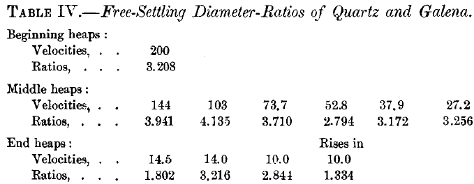
The beginning heaps are too near the galena to be fair; the end heaps are too near the slime to be fair; the middle heaps represent the best we have for ratios. Here again we see the ratios run from 3 to 3.5, more or less, as the ratios for quartz and galena grains settling under free-settling conditions. The average of the ratios of middle heaps is 3.501.
The second matter that is of special interest is the relation of the two ranges of hills. Note that the range of quartz hills is very close to the range of galena hills with only a very slight valley between the two. This is the characteristic result of separating grains by a free-settling classifier. We have now reviewed four different methods of testing by free-settling.
- by letting clusters of grains settle together,
- by letting individual grains settle one at a time,
- by spitzlutte and microscope to get the ratio,
- by spitzlutte and photograph to get the ratio,
and we find that they all give very nearly the same ratios of diameter for galena and quartz that are equal settling, namely, about 3 to 3.5 for the range from 0.5-mm. quartz to 2-mm. quartz.
Free-Settling Mill-Classifiers:
To get the free-settling method of classifying into a practical mill form, there are four things to be provided for:
- We must feed the pocket or bring in the mixed sands to be treated.
- We must subject them to a rough sorting in the pocket, lifting out the finished light product or overflow, using the feed-water with the rising water from the sorting-column to do this work, and settling the heavy unfinished product to the sorting-column.
- We must subject the above-named heavy product to a finishing-sorting in the sorting-column, allowing the finished heavy product to settle down and out, while the entangled light grains are separated and lifted up to the pocket again. This sorting-column must have the same velocity of rising current in all parts of a horizontal section across it.
- Finally, we have a pressure-box into which the wash-water is admitted and where it divides itself into two parts, that which rises and does the work in the sorting- column and that which goes down and out the spigot with the discharged sand. This pressure-box is a species of ticket-office entrance-gate through which the heavy grains are allowed to pass only after they are up to the standard and have obtained their ticket in the sorting-column above.
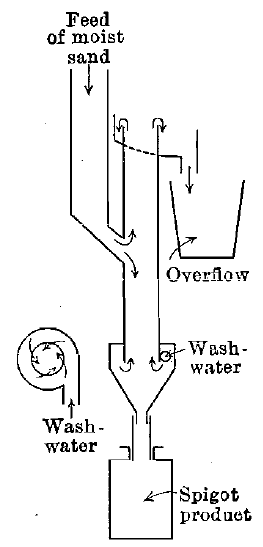
Fig.-3 Spitzlutte with Vortex
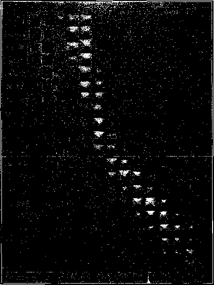
Fig.4- Free Settling Tests

Fig.5- Hog-Trough Classifier
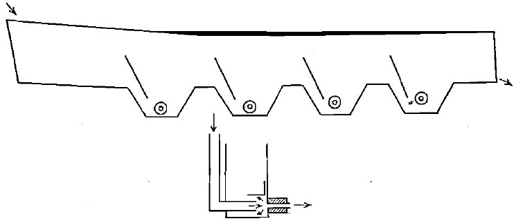
Fig.6- Calumet Classifier
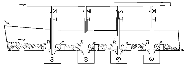
Fig.7- Evans Classifier
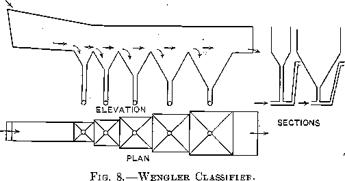
The sorting-column is the most difficult part of all the design, as it must not allow local down-currents which would carry slime down into the spigot-product, but it must have a steady, even rising current to carry up and out perfectly all the lighter grains that do not belong in the spigot-product. Classifiers are good or bad according as they do this one thing well or ill.
It may be further remarked that with all the pocket-classifiers, the water in the pocket must have the same rising-velocity as that in the sorting-column in order that they may both lift the same size of grain. For all these matters of computation of classifiers see my book.
The Lake Superior Hog- Trough Classifier—The advantage of this classifier, see Fig. 5, is its simplicity. Nothing is likely to happen to it that will put it out of order. The disadvantage of it is that it does not keep slime out of the spigot-products or prevent waste in fine free mineral in the jig- and Wilfley-table tailings. The fault is due mainly to two causes: (1) The sorting-column is only the thickness of a board in height, and, therefore, permits local down-currents to carry down slime. (2) The rising current is not positive in its action. When the water is increased by the cock the full effect does not take place until the water has risen in the annular space between the inner and the outer V to its full height, due to the increase. With this uncertainty, it is impossible to get good adjustments. Other harmful complications also arise.
The Calumet Classifier—This has the “hydraulic” water flowing directly at and in line with the plug-spigot, see Fig. 6, and the effect of adjustment of water is instantly felt. The slime is kept out of the spigots by the fact that the sand has to pass through an annular conical zone of clear water in order to get out of the spigot. The classifier is simple and easily kept in order and loses little mill-head. This was the first positive classifier.
The Evans Classifier—This has the advantage of simplicity, see Fig. 7, and of being easily kept in order. It has, however, one rather serious disadvantage in the fact that it requires greater force in the rising current on the up-stream side, B, of the regulating-disk, C, than on the down-stream side; this necessitates using more water on the down-stream side than is necessary for cleaning the sand, and makes the classifier a large water-user.
The Wengler Classifier — This consists of hopper-shaped pockets, see Fig. 8, with feed and overflow of all on the same level. It has small vertical pipe sorting-columns at the points of the hoppers. This was a very early design, made before the classifier was understood. It was probably never put into use but once and then immediately thrown out. It has one fatal error: the hopper-shaped pockets with small sorting- columns below must necessarily fill up with hard sand-banks, for the grains of sand that are just too small to settle in the rapid current of the small sorting-column are much too large to be raised in the weak rising current in the large area at the top of the hopper-pocket. I have put this in simply as a warning to the would-be designer.
The Linkenbach Classifier.—This is one of a number of designs, see Fig. 9, given by Linkenbach in his book, and shows a simple way of overcoming the trouble of the sand-banks referred to under Wengler. The method is to have the overflow of any one pocket above the level of the feed of the next. This gives a plunging-stream feed to all the pockets and breaks up the sand-banks, carrying forward the sand to the next pocket. This method is not systematic and may carry forward into the later pockets larger grains than belong there.
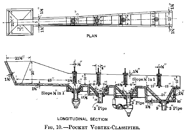
The Pocket Vortex-Classifier—By having the pockets shallow and graded in size, Fig. 10, so that an earlier smaller pocket settling large grains will have a stronger rising current, while a later larger pocket settling smaller grains will have a weaker rising current, the roughing-work of the classifier of lifting out the most of the lighter grains is easily and perfectly done. The sorting-column below is put on to complete the work of cleaning the spigot-product. The hurtful down-currents carrying slime into the spigot are prevented by admitting the “hydraulic” water in a vortex fitting. This gives a helical rising-current, that is, a current flowing up in the direction of the thread of a screw. This classifier is simple and complete in its action.
The Tank Vortex-Classifier—This classifier, Fig. 11, adds to
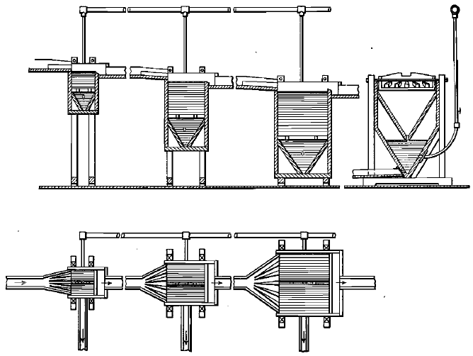
Fig. 9 – Linkenbach Classifier
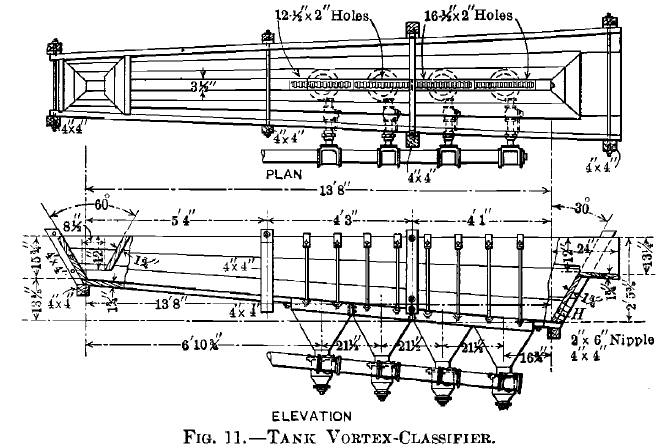
 the advantages of the pocket vortex-classifier the fact that all the pockets are merged into one tank, and no careful grading of pockets has to be allowed for. In case the design provides for a larger amount of feed-water than is used, then the resulting tendency to form a bank is overcome by a safety-spigot, H, in the end of the tank. This safety-spigot product ranks as overflow and may be treated with the latter or as a separate product, as preferred. It will have slime mixed with its fine sand. This classifier is simple and complete in its action.
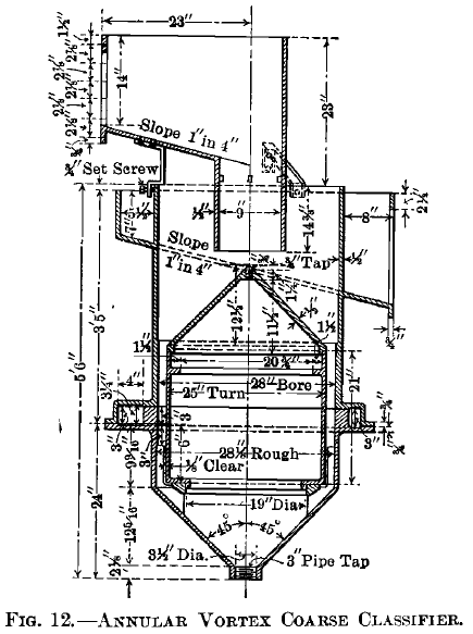
The Annular Vortex Coarse Classifier—This classifier, Fig. 12, is generally used with one pocket only, and has found employment in two directions: (1) for cleaning the fine overflow of the log-washer when used on brown iron-ore, where it saves 25 tons a day of good iron-ore for the furnace; (2) for separating coarse sand for feeding the Hancock jig from the fine sand for the Wilfley table. It makes use of the helical current of the vortex-classifier for very much larger quantities than can
be used in a simple pipe sorting-column, and does so without the danger of hurtful local down-currents to carry slime into the spigot. In fact, it can be designed for almost any capacity.
The Annular Vortex Fine Classifier—This classifier, Fig. 13, has an enlarged cone above the annular sorting-column to enable the classifier to deliver a fine overflow-product of any degree of fineness by the large diameter and consequent small velocity of the overflow. At the same time it delivers a spigot- product free from slime.
The Callow Slime-Cone and Water-Cone—These cones, Fig.14, are of two kinds: (1) the slime-cone, which draws sand and some slime from the spigot and sends slime into the overflow; and (2) the water-cone, which draws sand and slime from the spigot and clear water, or nearly clear water, from the overflow. They have no rising “hydraulic” water. They are really settling-tanks. The reason for mentioning them here is to bring out the advantage they possess over the rectangular settling-tank. An ordinary settling V-tank 6 ft. wide has an overflow 6 ft. wide; an 8-ft. water-cone has an overflow 24 ft. wide. If the two tanks have the same quantity (gallons a minute) to treat, the V-tank will have four times the amount of overflow per foot that the water-cone has;
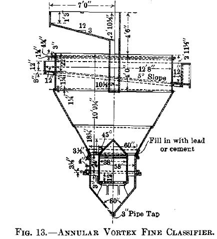
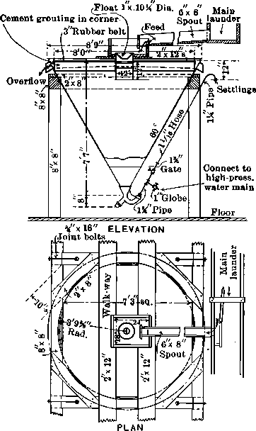
Fig.- 14 Callow Settling Cone
the water approaching the overflow will have four times the velocity, and will therefore carry much larger grains into the overflow.
The Work of a Free-Settling Classifier:
Fig. 15 is introduced to give more clearly the exact idea of what happens in a free-settling classifier. To the left of this figure will be seen a diagram representing a tall glass tube of water in which grains of sand can be allowed
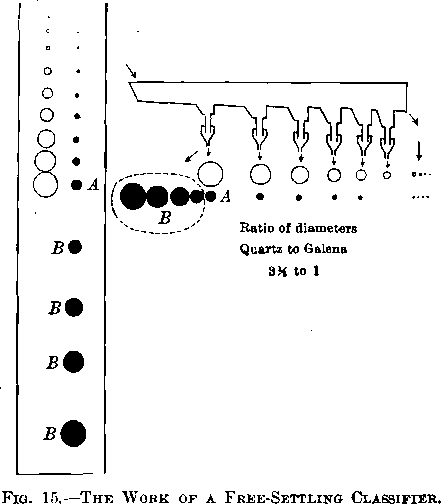
to settle, and in which they will settle with velocities according to their size and gravity. The open circles at the left represent quartz with a gravity 2.64, and they show that the largest grain goes the fastest and the smaller grains diminish in velocity as their diameters diminish. Similarly, the black circles represent galena with a gravity 7.5. Here the grains also settle according to their size, the larger going faster, but the galena grains settle much faster than quartz of the same diameter. We at once notice that the grains are paired off, that there is in each pair a smaller grain of galena opposite the larger grain of quartz which is equal settling with it, and the quartz grains are, as we have already seen, about 3.5 times larger in diameter than the galena grains. These grains having the same velocity are said to be equal-settling grains under free-settling conditions, and they naturally belong in the same spigot of the classifier. If now we suppose this complete group of grains to be laid in a horizontal position underneath the classifier, we shall see that each spigot receives its large grain of quartz and small grain of galena according to the equal-settling velocities that have been discussed in the early part of this paper, that in succession the second spigot has smaller grains than the first, the third has smaller grains than the second, and so on, diminishing until we reach the final overflow, which contains the finest grains of all; but the most striking thing is the remarkable difference shown by the first spigot, for besides the equal-settling grains of quartz and galena, A, we have all the added increment, B, of larger grains of galena, which find their way into this spigot in addition to the regular classified grains of quartz and galena, making the first spigot uniformly very much richer than any of the subsequent spigots. A supplementary condition occurs also in the overflow. Here the largest grain of quartz is much larger than the largest grain of galena, and this portion is the truly-classified product; but in addition to this the quartz ranges down to the finest dust, and the galena also making this product has an added increment of extra-fine grains over and above the truly-classified grains, making it differ from the truly-classified products of all the intermediate spigots.
We see that all of the products of the classifier, except the first spigot and the last overflow, are truly-classified products ; that is to say, they contain larger grains of quartz and smaller grains of heavy mineral, but that the first has an added increment of a large quantity of coarse grains of the heavy mineral, which enrich it very largely, while the last overflow has an added increment of tine material over and above the truly-classified grains. These facts showing the difference between the coarsest and finest products render it necessary to give these two products special consideration when they are being treated by concentrating-machines.
Hindered-Settling Tests:
Hindered-Settling with Steady Current—If in Fig. 16, after turning the water on moderately by the valve, G, filling the glass tube and hopper to the overflow, we charge mixed quartz and galena grains from 2 mm. to 0 in size, and as the rising current of water is too strong to allow them to go through the 0.25-in. tube constriction at the bottom, the grains will quickly arrange themselves according to their ability to settle under these conditions, fine grains at the top, coarse grains at the bottom, and it will be found that they are all in movement, teetering or oscillating up and down through short distances, like the grains of sand in a boiling spring. If one should take out a grain from any part of the tube and drop it in at the top, it would settle down until it came to approximately the same position as that from which it was taken. These grains have arranged themselves according to the laws of hindered-settling particles. If now we slacken the water and draw off a bulb full of sand, and we do it a second time with a new bulb, and a third time and so on, we get a series of products beautifully classified. We may now size these products on our series of sieves and lay them out on a board and photograph them, Fig. 17. After doing this, we can compute for any bulb the average diameter of the quartz grains, and the same for the galena grains, and divide the former by the latter and get the diameter-ratio for quartz and galena under hindered-settling conditions. Such a computation for bulbs 4, 5, and 6 gave the results in Table V.

This (First discovery) shows a remarkable advance from the diameter-ratio of free-settling. See also the wide valley between the quartz and galena heaps in Fig. 17. The same work has been done for the 13 minerals referred to under Free-Settling, and the hindered-settling diameter-ratios given in Table XII. were obtained. See the paper, Close Sizing Before Jigging.
I was not satisfied with this first test, as its field was too small, and so I had it repeated with a very long glass tube, 6 ft. long, Fig. 18, which yielded 45 bulbs, and from them, after sizing, the photograph, Fig. 19, was obtained. Diameter-ratios were computed from these bulbs and gave Table VI.
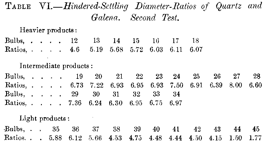
Throwing out of the count the first few heavier products as being too near the galena to be fair, and also a few of the light products as being too near the slime to be fair, we get the above mentioned ratios from the intermediate products, and their average is 6.92, showing a still greater advance over free-settling diameter-ratio than was shown in the first hindered-settling test. Observe also the wonderfully wide valley between the quartz and galena heaps in Fig. 19.
Hindered-Settling with Pulsating Current—With a view to see whether anything was gained by the use of intermittent pulsions in the place of steady current under hindered-settling conditions, the following experiment was tried: Fig. 20 shows a hindered-settling tube which has been cut apart and a sieve has been placed across it as a horizontal jigging-sieve. Tests made with this tube indicated that the ratio of diameters was not advanced over that obtained by the steady current; and photograph, Fig. 21, from this work is identical with photograph, Fig. 17, without pulsations. The tests, however, indicated that the pulsating current could be made to act much more evenly than the steady current; that is to say, the avoidance of downward hurtful currents could be gained to a much greater

Fig. – 16 Pointed Tube, or Hindered-Settling Spitzlutte
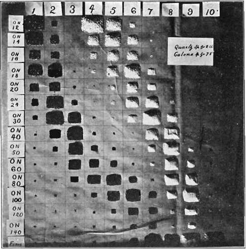
Fig. – 17 Hindered-Settling Tests with Pointed Tube

Fig.- 18 Lewis and Richmond Hindered-Settling Tube with bulb Drawn 45 times
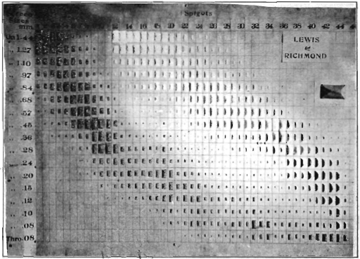
Fig.- 19 Hindered-Settling Test with long Tube
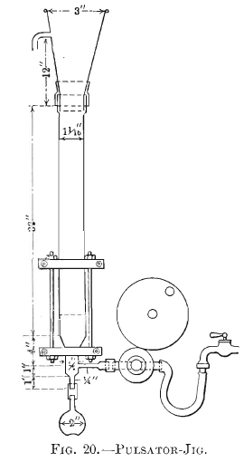
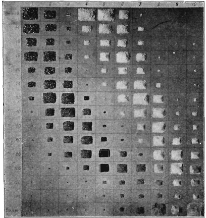
Fig.- 21 Hindered-Settling Test with Pulsator Jig
degree by the use of a pulsating current acting evenly all over the surface of the sieve than could be done with a steady current, in both cases acting under hindered-settling conditions.
Method of Getting Hindered-Settling:
It will be seen that the hindered-settling apparatus has a constriction whether by narrowing the tube or by the use of a sieve, up through which the rising current comes, and that the tube widens out to a larger diameter and area in the hindered-settling chamber above the constriction. This is the essential feature of the method of getting hindered-settling, namely, a hindered-settling chamber above and a constriction below it, with the whole current rising up through the two.
Cause—The cause of the difference between hindered-settling and free-settling appears to be that with free-settling both the quartz and the galena are settling in water with a specific gravity of 1, and they obey the law laid down by Rittinger for particles settling in that liquid. With hindered-settling, however, the grains are settling in liquid much denser than water, with perhaps 1.5 specific gravity, due to the crowding mineral grains. This, when worked out mathematically, should give a diameter-ratio of 6.9 between quartz and galena, and this is exactly what has been obtained in Fig. 19.
Effect—The effect of hindered-settling and the advanced diameter-ratio is twofold: first, the slime is kept out of the spigot- product more perfectly than by any other method known to me; second, the advanced ratio really means that the hindered- settling classifier has done more to help the concentrating-machines which follow to do their work than has the free-settling classifier. In proof of this, the reader is asked to compare the hindered-settling photographs, Figs. 17, 19, and 21, with the free-settling photograph, Fig. 4. These photographs all represent the work of a classifier as a preliminary machine followed by screens as the finishing machine. Notice how much farther the galena is removed from the quartz in the hindered- settling photographs than in the free-settling photograph. Notice also how much more galena is concentrated into the first spigot of the hindered-settling than is in the free-settling classifier.
Requirements—As the teeter-chamber (hindered-settling chamber) must have a constriction below it, it is necessary to know what should be the ratio of areas between the two. Clearly it cannot be so large a ratio as in Fig. 16, namely, (¼)² to (7/8)² = 12.25, because when the current was strong enough to cause full teeter in the teeter-chamber it was too strong in the constriction to allow any grain to go down, and it cannot be a very small ratio, as then it would simply be a free-settling classifier. Clearly there must be some ratio that is better than all others. I have worked long at this point, and I think I now have end figures in sight. Up to date I can say that a ratio of areas of 1 to 4 will work, that is, it will give a teeter-chamber above and a discharge through the constriction at the same time.
The Jig:
From what has already been said it will be understood that the act of pulsion or the movement of rising current in jigging is identical in its action with the hindered-settling rising current. The plunger-jig, however, adds another very important feature, namely, the act of suction, or return-downward current. This is caused by the rising of the plunger when returning preparatory to the next downward or pulsion stroke.
In the paper, Close Sizing Before Jigging, three series of tests were recorded which threw a great deal of light on this question.
A little glass hand-jig, Fig. 22, was used in such a way that the water at no time reached the top of the glass side, A, A. The lift-pump valve-action of the sand grains soon brought the water to its maximum height within the glass, and then it was evident that the amount of water that rose through the sand during pulsion was equal to the amount of water that fell during suction; that is, we had jigging with strong suction.
The above glass jig was filled up with water until the water stood above the glass sides, A, A, of the jig. When so adjusted a considerable portion of the water which rose during pulsion could overflow, and therefore the amount of water which came down during suction was very much reduced. It was then jigging with mild suction.
The glass pulsator-jig, Fig. 20, of this paper has pulsion only, and therefore represented jigging with no suction. Six tests were made in each series with each of the above three sets of conditions, using the same size of quartz in all cases, but varying the size of blende from coarse to fine in each of the three sets. The results are given in Table VII.
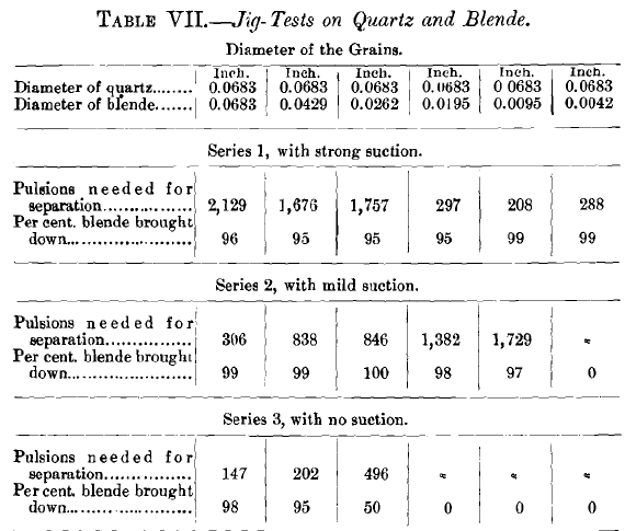
The results show that with a closely-sized product, 0.0683-in. quartz and 0.0683-in. blende, strong suction is very slow (2,129 pulsions needed), while no suction is extraordinarily rapid, 147 pulsions needed (Second discovery). On the other hand, with second spigot of a classifier where the diameter of the quartz is 3.5 times the diameter of the heavy mineral (0.0195 x 3.5 =
0. 0683), strong suction is very rapid, 297 pulsions needed, while no suction would never make a separation (means infinity or never). Mild suction appears not to have been very satisfactory in either case.
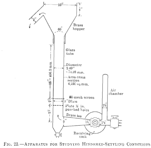
Full Teeter—When a water-current rises, Fig. 23, through a mass of sand where the grains are all of one size, if very slow it will not move the grains at all; if faster, the grains begin to move. By gradually increasing the current, we reach a speed where all the grains are moving so freely that they are immediately stratified according to gravity. When this speed is reached, we call the condition “just full teeter,” that is, the weight of the grains is balanced by the rising water-current, and as a result, they are teetering up and down like the grains of sand in a boiling spring.
The data in Tables VIII., IX., X., and XI. are the result of many trials, some of them as many as 20, before adopting the results.
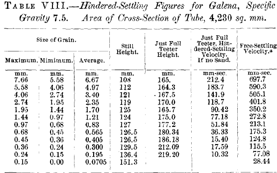
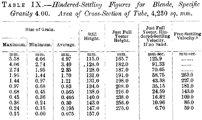


Grains of quartz 3.4 mm. in diameter, Table X., require for just full teeter a rising current of 68.7 mm. a second (that is, a quantity of water that would give this velocity if no sand were present), while these same grains under free-settling conditions settle at the rate of 207 mm. a second. Galena grains 3.4 mm. in diameter, at just full teeter, see Table VIII., require a rising current of 141.9 mm. a second, while the same grains settle under free-settling conditions at the rate of 505 mm. a second. Let us see to what conclusion these interesting facts lead us. See Fig. 24. If we are concentrating 3.4-mm. quartz and galena grains in a pulsator-jig, we must give the galena 141.9 mm. a second velocity of rising current in order that they may be at full teeter or liquid stratification. This 141.9 mm. a second is far above the just-full-teeter velocity of quartz, in fact it is nearly up to the free-settling velocity of quartz. We see, then, that when galena is in hindered-settling condition at just full teeter the quartz is so separated that the grains are far apart. We have in this phenomenon the answer to the question, why is it that the pulsator-jig can treat ore so much more rapidly than the plunger-jig? for in the pulsator-jig a grain of galena meets no resistance to settling through the quartz layer
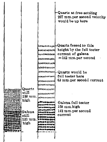
Fig.- 24 Behavior in Pulsator Jig of Galena and Quartz 4.06 to 2.74 mm. in Diameter
lying above the galena (Third discovery), while on the other hand, if we drop a grain of galena on the bed of a plunger- jig and watch it, it takes 5 or 10 pulsions before it settles into the quartz far enough to get out of sight. This clearly explains the remarkably high capacity of the pulsator-jig.
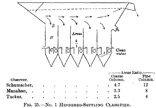
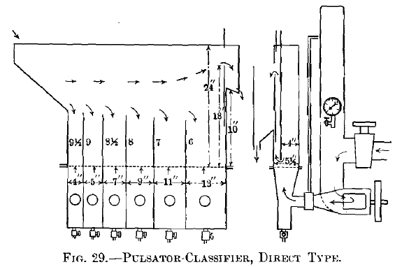
Economy of water should be largely realized by the use of hindered-settling. Since it requires only one-quarter, more or less, of the velocity required by free-settling to do the work, it should require only one-quarter the quantity of water. As the designs are being improved this economy is more and more being realized. For example, in the direct pulsator-classifier, Fig. 29, the quantity required is extraordinarily small, and in the pulsator-jig the water consumed is less than in the plunger- jig. The No. 1, No. 2, and No. 3 hindered-settling classifiers, Figs. 25, 26, and 27, have not yet been measured for water, but I believe they will economize water.
Hindered-Settling Mill-Classifiers:
To get the hindered-settling method into practical mill form, one must provide for each compartment:
1. means of feeding it with pulp. See B, Fig. 25.
2. a teeter-chamber or hindered-settling chamber, H, in which the separation takes place.
3. a constriction at the bottom, C, of the teeter-chamber, down through which the heavy product may or may not go, according to the design.
4. means of removing the product by overflow-discharge or spigot.
To put the hindered-settling principle into practical final form I have made five designs:
No. 1 hindered-settling vortex-classifier, Fig. 25.
No. 2 hindered-settling vortex-classifier, Fig. 26.
No. 3 hindered-settling vortex-classifier, Fig. 27.
The hindered-settling inverted pulsator-classifier, Fig. 28.
The hindered-settling direct pulsator-classifier, Fig. 29.
Taking these up in order:
No. 1 Hindered-Settling Vortex-Classifier, Fig. 25, shows at a glance its relation to the hindered-settling test-tube, see Figs. 16 and 18. Here one sees the hindered-settling chamber, H, and below it the constriction, C, for each of the pockets, and again below the constriction and pressure-box furnishing the upward current in a helical form and also the water for the spigot. This classifier submits the sand to hindered-settling treatment in the hindered-settling chamber, the grains there being in the condition of teeter, the heavy grains quickly going down and out, and the medium grains, remaining at full teeter, act as a filter for filtering out the fine slime. Fine free mineral is scarcely discernible in the tailings of Wilfley tables treating these products.
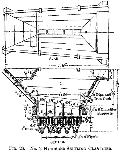
No. 2 Hindered-Settling Vortex-Classifier, Fig. 26, has constriction considerably longer than in the No. 1, and it has the additional feature of a lot of little vortex jets (20 in all) for giving a whirling current to the water in the constriction. This makes it still more impossible for the constriction to have a downward current on one side with upward current on the other, carrying slimes into the earlier spigots, and thereby guarantees tailings free from fine free mineral.
No. 3 Hindered-Settling Vortex-Classifier, Fig. 27, instead of a hindered-settling chamber above, and a constriction below with vortex jets in it, as in No. 2, has these two parts merged into one in conical form with inflowing jets all the way from the
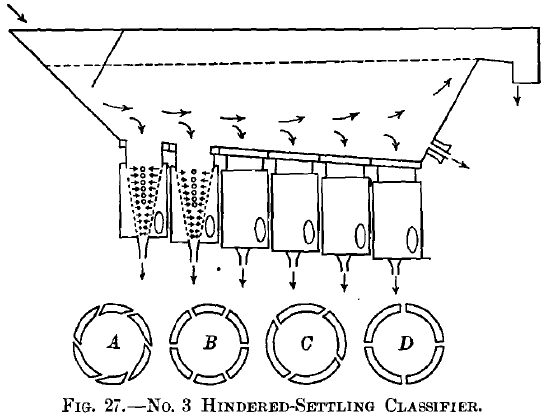
top to the bottom. The inflowing jets, however, have three variations, which should be mentioned. They are in layers, alternately radial jets, B, D, and vortex jets, A, C, the vortex or tangential jets breaking up a possible sand-bank in the form of a shell around the margin, and the radial jets breaking up a possible core-bank of sand in the center. Further, the upper holes, C, D, are smaller in size, 0.25 in. in diameter, more or less, and only four to the circle or layer, whereas the lower holes, A, B, are larger in size, 0.5 in., more or less, in diameter, and six of them to the circle or layer. The conical form, combined with the arrangement of jets just referred to, gives maximum rising current two-thirds of the height down, and gives a steadily-diminishing velocity of rising current as the water rises in the cone. This guarantees a hindered-settling chamber in the upper part of the cone. This arrangement lowers the neutral plane which lies between the rising current which does the sorting and lifts out the light stuff, and the descending current which carries down the heavy grains to be discharged at the spigot. By putting this plane considerably lower, it is believed that this No. 3 classifier is more perfect than the No. 2 from the theoretical point of each, and by having layers of jets made alternately radial and tangential, it is believed that the elimination of possible harmful currents is thoroughly accomplished, and that tailings made from treating these products will be free from fine free mineral.
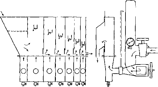
Fig.- 28 Pulsator Classifier Inverted Type
The Hindered-Settling Inverted Pulsator-Classifier, Fig. 28, is another mode of preventing hurtful downward currents. It is believed that oft-repeated pulsations will give an even rising current when passing up through a mass of sand; first, because it comes by pulses, and secondly, because it comes through the sieve at high velocity compared with full teeter. If the meshes of the sieve have one-quarter the area, then the velocity when passing the sieve is four times that in the space above. The up-coming water attacks all parts alike through the meshes of the sieve, which act as the constriction. This classifier, Fig. 28, has been designed to make use of this principle. It will be seen from the figure that the feed-water and sand enter the apparatus in the feed-hopper, and that the feed-hopper has a pulsating bottom to prevent the sand from solidifying and forming an obstruction on the bottom. The pulsation is given by the pulsating rising current up through the sieve in the feed- hopper as in all the succeeding compartments. The liquefied sand then passes into the first compartment and the pulsating rising current lifts out all of the lightest grains of slime and sand as overflow. The first two products carry all the slime and give the densest slime of any classifier known to me. All the heavier material finds it way forward by passing under the partition-gate into the second compartment, receiving its force to do so by the diminished height of overflow, and, therefore, head of water in the second compartment as compared with the first. The second compartment again repeats the act of the first in lifting out the lighter parts by the pulsating rising current, allowing the heavy parts to flow into the third by the diminished head of the third as compared with the second, and so on to the fourth, fifth, and sixth compartments. A safety- spigot in the end just above the sieve of the sixth compartment may be used in case an excessively heavy bank forms in that compartment. This gives a seventh product. Each compartment of the series discharges a heavier product than the one before it, and each furnishes a very perfectly classified product. The slimes that come in with the feed are taken out by the first and second compartments and appear in these two products. The Wilfley tables which treat these two slimy products cannot make tailings free from fine free mineral with one treatment, as all the other Wilfleys can. They require an additional treatment. The tailings of the Wilfley tables treating the third and fourth, fifth and sixth spigots of this classifier, are as clean and free from fine free mineral as it is likely will ever be obtained in mill practice. One may say that they are commercially free from fine free mineral. The fifth and sixth products may yield tailings on jig or Wilfley table, with sufficient amount of included grains to make their further treatment by recrushing and re-treatment necessary. The latest form of revolving- cock for getting the pulsating current is designed with the feed-water entering the end of the hollow cylindrical revolving part and discharging through two ports on opposite sides. This makes it a perfectly balanced valve and prevents the valve from pressing too hard on the valve-seat. This alternate opening and closing of a revolving-cock gives an alternating condition of rising current and repose, repeated perhaps at the rate of 200 times a minute, and produces the desired result. By using a single revolving-cock and distributing the current through seven regulating-cocks, the seven compartments can be furnished each with its own pulsating rising current. The air-chamber used with this apparatus differs from the air- chambers ordinarily used with pumps and other hydraulic apparatus, in that the latter are used simply to diminish the shock due to the water-hammer, while this air-chamber is used mainly for the purpose of giving a sudden impulse to the water the instant the revolving-cock is open. This impulse is due to the elasticity of the air, and without it the classifier could not be
operated. The avoidance of shock is necessary with the classifier, as it is with all hydraulic apparatus, but it is not the main feature for which the air-chamber is used. For the method of cleaning up the first and second products of this classifier, see the description of the treatment of the slimes of the direct pulsator-classifier. The method in both cases is the same.
The Hindered-Settling Direct Pulsator-Classifier, Fig. 29, differs from the inverted only in the fact that the pockets are not connected at the bottom of the dividing partitions, and in consequence the earlier pockets overflow into the later within the machine, instead of overflowing as separate products. All the compartments receive pulsating rising current, and as a result the first compartment gives the heaviest largest grains and the final overflow gives the lightest. The several compartments discharge their products either by the gate-and-dam discharge, commonly called the cup-discharge, used in jigs, or by the ordinary plug-spigot, with or without a shield behind it, beneath which the discharge sand must come. The ordinary spigot is the simpler and is very good. It yields its series of products graded from coarse to fine. It is not difficult with this classifier to bring the discharge of the first compartment up to a quality of finished concentrates, and in this way eliminate one jig from the set of finishing-machines. If the first be made a finished product the second can go to the Harz jig, and it will be found to give tailings free from fine free mineral. These tailings are free from fine free mineral, but they may have included grains, and require recrushing and re-treating in consequence. The succeeding spigots, third, fourth, fifth, and sixth, can all give tailings free from fine free mineral on Wilfley tables. This fulfills the requirements of milling, leaving only the slime as the single product to be finished, and this can be finished by running it upon the Wilfley table, making tailings containing fine free mineral, which are finished by Callow screen, sending the undersize to a vanner. The oversize of the Callow screen and the tailings of the vanner will both be free from fine free mineral. The slime from the Wilfley table will have to be treated by vanners or by any of the slime-methods best approved in the district under consideration.
The Hindered-Settling Pulsator Pebble Sand-Slime Cone, illustrated in Fig. 30, has been tried on a small scale and has shown remarkable abilities for separating sand and slime. By using pebbles, perhaps 1 in. in size, supported on a very coarse screen, a pulsating current furnishes a very perfect separation of sand from slime. When one realizes that the rising current in the interstices is about four times what it is in the space above, one sees that there is great opportunity for regulation of the rising current and for the avoidance of downward currents carrying slime into the sand.
The Work of the Hindered-Settling Classifier:
Fig. 31 represents the work of a hindered-settling classifier. The side tube represents here the relations between the grains
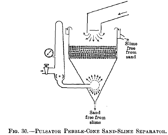
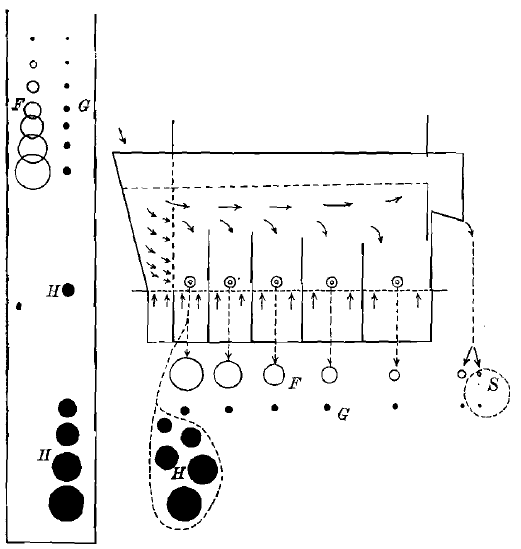
Fig.- 31 Work of Direct Pulsator Hindered-Settling Classifier
of quartz and galena under hindered-settling condition, namely, the quartz grains in juxtaposition with the galena grains are 6.9 times the diameter of the latter. Laying this diagram down under the direct pulsator-classifier, we have an illustration of the products made by a hindered-settling classifier. Just as the free-settling classifier had an added increment, H, of heavy mineral in the coarsest spigot, truly-classified products in all the between spigots, and an added increment in the finest product of slimes, so has this hindered-settling classifier. It, however, differs from the free-settling classifier in having a very much larger ratio between the diameters of the grains in juxtaposition in the between products, namely, the quartz grains are 6.9 times the diameter of the galena grains associated with them, and as a consequence the coarsest product has a much larger proportion of all the values in it than was the case in the free-settling classifier. The amount of water in the spigots and in the overflow is much reduced from that in the free-settling classifier. The fine free mineral grains liable to contaminate the tailings of the concentrators that follow are much easier kept out from those tailings.
What I have said here of the direct pulsator-classifier is in the main true of hindered-settling classifiers No. 2 and No. 3 and also of the inverted pulsator-classifier. The latter does not reduce the water in the spigots so much, but reduces the water in the overflow more.
Mill Concentrators, Some of Their Faults and the Benefits Derived from Sizing or Classifications:
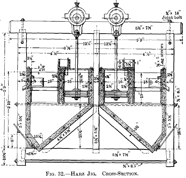
The Harz Jig.—Fig. 32 represents the Harz jig. We come now to the study of the effects of improved classification upon the different machines, and we will first take up the Harz jig, and call attention to the fact that this jig has a plunger which falls and rises, and as it does so, it first sends a pulsion of water up through the grains of sand, causing the same action as the hindered-settling classifier, and, second, the water goes down through the bed of sand, sucking down into the hutch the fine grains which are lying in the interstices of the quartz.
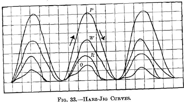
Fig. 33 represents the curve of a Harz jig where the movement down and up of the plunger is by simple eccentric, and these curves represent in vertical direction the distance up and down of the movement, and in horizontal direction the time elapsing while the movement is being made. The curve marked P represents the movement of the plunger: the curve marked W represents the movement of the water; R, the movement of the rock or quartz, and O, the movement of the ore or heavy mineral. The describing pencil moved from left to right, as indicated by the arrows, so that the left-hand side of the curves represents the pulsion or rising current of water, and the right- hand side represents the suction or downward rush of water.
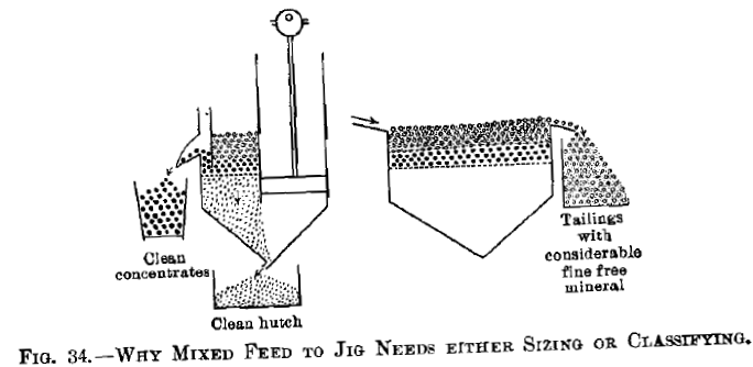
Jigging Mixed Feed—Fig. 34 shows points of strength and of weakness in jigging mixed sizes upon a Harz jig. It can yield a large quantity of good concentrates in the side-discharge, it can yield a large quantity of clean hutch-work in the grains which pass down through the sieve, but it fails in the fact that the tailings carry a large amount of fine free mineral which is too fine, and therefore too high up in the bed, to be drawn down into the hutch by the suction of the plunger.
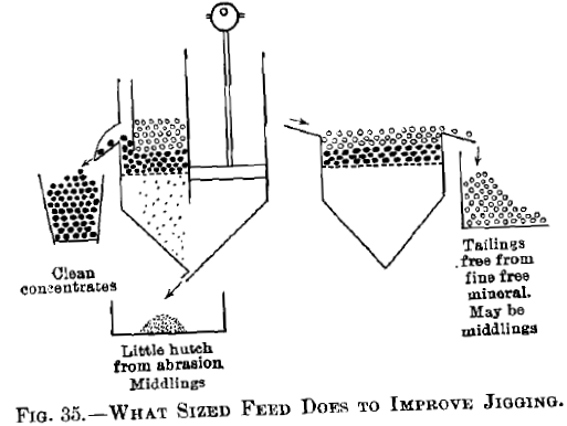
Jigging Sized Feed.—Fig. 35 shows the improvement in jigging that is brought about by jigging a sized product. Here the side-discharge is clean concentrates. The amount of hutch is extremely small, and consists of particles abraded from the ore
on the jig-bed. The tailings are free from fine free mineral. They probably have included grains, and if so may require recrushing, but the removal of fine free mineral from the tailings places the jig in the most favorable aspect.
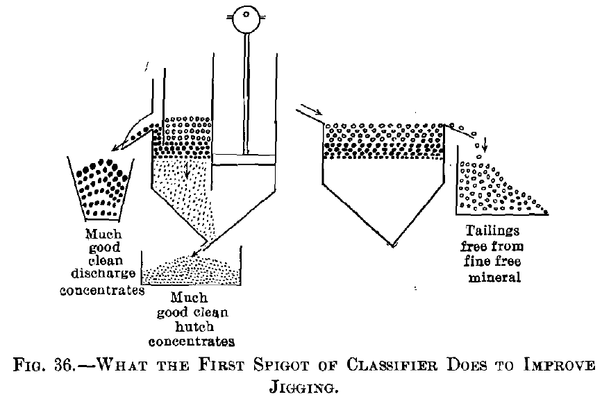
Jigging First-Spigot Product of Classifier.—Fig. 36 shows the improvement that may be had by jigging the first-spigot product of the classifier. Here the side-discharge concentrates and the hutch are both clean and very large in quantity, and the tailings are free from fine free mineral, because, while a certain amount of small grains of heavy mineral finds its way into the first spigot, the grains are not small enough to go into the tailings as fine free mineral.
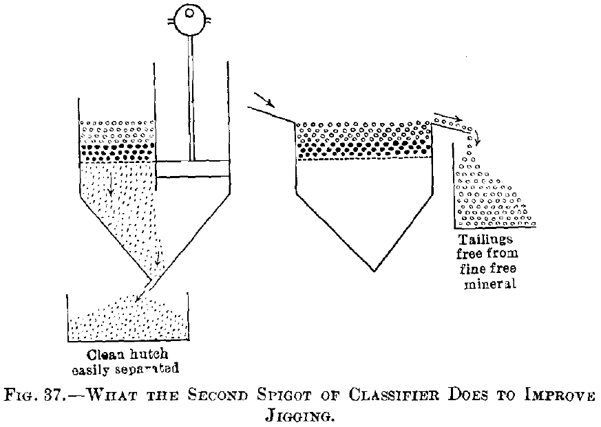
Jigging Second-Spigot Product.—Fig. 37 shows improvement due to second spigot of the classifier. Here the coarse free mineral is all wanting, and as a result, we simply make hutch-work and considerable of it, and this hutch-work will be clean concentrates. This jig will require a bed of coarse heavy mineral added to it. The tailings will be free from fine free mineral, because, while the grains of heavy mineral are much smaller than the grains of quartz, they are not fine enough to go into the tailings as fine free mineral.
Free-Settling and Hindered-Settling for Jig-Feed Compared:
Why are the two coarsest spigot-products of a hindered-settling classifier better for jig-feed than the two coarsest spigot- products of a free-settling classifier? Answer. The coarsest spigot-product is much richer, and in consequence the jig has less quartz to separate from it, and a larger proportion of heavy mineral is saved from the coarsest product. The next to the coarsest spigot has already had removed from it all the concentrates which go into the automatic side-discharge (cup-discharge), and the only work left for the jig to do is the suction- work of putting the small grains of concentrates into the hutch. For this work a bed of coarse mineral will have to be placed on the jig-screen, to prevent the quartz from being sucked down into the hutch. Spigot-products finer than the two coarsest will ordinarily go to the Wilfley table. If the third in size has to go to a jig, what was said of the next to the coarsest will be true of the third also.
Why is the second- or third-spigot product of a hindered-settling classifier better feed for a plunger-jig than the second- or third-spigot product of a free-settling classifier? Answer. In the paper, Cycle of the Plunger Jig, it is shown that rapid suction and rapid jigging take place when the ratio of diameters of quartz and heavy mineral is 3.52 or larger. It is also shown that slow suction and slow jigging take place when the ratio of diameters is 2.61 or less.
Taking from the paper, Close Sizing Before Jigging, the free-settling ratios for a fall of 9 in. per second, or 228.6 mm. a second, and the hindered-settling ratios as obtained from the average of the three columns computed, we have Table XII.
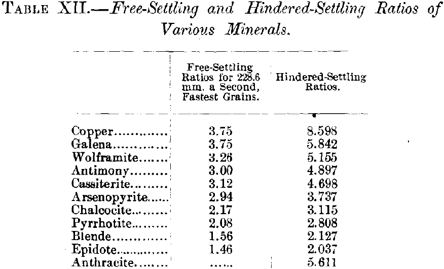
Assuming that 3..52 is the dividing-line between easy jigging and difficult jigging with much suction, then we have: free- settling only includes copper and galena as having the favorable ratios, while hindered-settling includes copper to arsenopyrite and all the minerals between as having a ratio favorable to suction.
Whether the jig is fed with products from free-settling classifier or hindered-settling classifier, the tailings will be free from fine free mineral, if the classifier is a good classifier and is properly run.
How to Improve Fine Jig-Tailings Which Have Resulted From Mixed Feed:
The loss is mostly fine free mineral, and a fine screen will put all this into the undersize, which can go to Wilfley table. The oversize will be clean waste up to the limit possible. If it has too much included grains it will need to be recrushed.
The Pulsator-Jig—Fig. 38 represents the plan, longitudinal and cross-sections of the pulsator-jig. Here the pulsations are given to the sand from the forward current due to the opening and closing of the cock, which revolves 100 times a minute, more or less, giving about 200 forward pulsions, with an instant of repose between the pulsions. Obviously the hutch-product is somewhat reduced in this jig, and on that account its main field lies in jigging sized products. If there
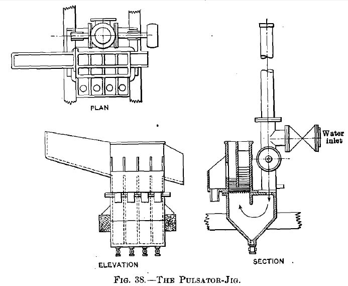
are small crumblings coming off from the concentrates, due to abrasion, these small grains may find their way into the tailings. If it is used as a machine for treating the first-spigot product of the classifier, some of the finest grains in this classifier-product may find their way into the tailings. This is a disadvantage of the pulsator-jig. It is, however, completely overcome by screening the tailings, in which case the tailings-oversize is turned out just as clean as the best Harz-jig tailings, while the undersize goes back to classifier and to Wilfley shaker table. The advantages gained by the pulsator-jig far more than compensate for the above-mentioned disadvantage. By omitting the suction, the matting together of the sands in the bed of the jig, which is so marked in the Harz jig, is avoided, and as a result the jig has a very large capacity fordoing work. The mistake one is liable to make, in starting a pulsator-jig for the first time, is to cut down the added “hydraulic” water so as to make the upper quartz layer about like that on a Harz jig. When this is done the bed of heavy mineral below is very hard and immovable. To correct this the quartz bed must be so completely liquefied that the bed of heavy mineral is at full teeter below. When this has been done the great capacity of
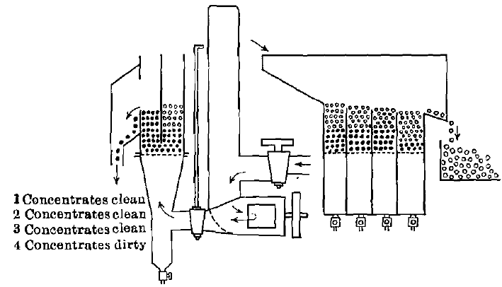
Constumes one-twentieth the power; uses about one-half the water; occupies about one-fifth the space. Makes a little fine free mineral in the tailings, which is saved in recrushing and re-treatment or by screening.
Fig.- 39.–What The Pulasator-Jig Does to Improveme Jigging
the pulsator-jig will be at once available, and its ability to control its discharges will also be available. Summing up the advantages of the pulsator-jig over the Harz jig, the former requires 5 per cent, or less power for driving, it requires perhaps one-half the water, it requires less than one-fifth the space in the mill, and the only disadvantage incurred in order to gain these improvements is that it may be necessary to screen the tailings.
Fig. 39 represents a pulsator-jig making its discharge, concentrates and middlings, and making its tailings with a small quantity of fine free mineral.
Comparing the pulsator-jig with the plunger-jig as they have been tested in the mills:
At Great Falls, Mont., a 4-compartment pulsator-jig with compartments 4 in. square displaced 8 plunger-jigs with 2 compartments each, and with compartments 19.5 in. wide and 39.5 in. long. The plunger-jigs had 12,324 sq. in. of sieve, while the pulsator-jig had 64 sq. in., or 1 sq. in. of sieve in the pulsator-jig did the same work as 192 sq. in. in the plunger- jig. The pulsator-jig tailings were slightly higher in copper, but the plan of screening them to remove the small quantity of fine free mineral had not then been devised.
At Britannia Beach, British Columbia, one 4-in. 6-compartment pulsator-jig has replaced five 2-compartment plunger-jigs with compartments 24 by 48 in. The total plunger-jig screen- area was 11,520 sq. in. The total pulsator-jig screen-area was 96 sq. in. In this case 1 sq. in. of sieve-cloth did the work of 120 sq. in. of sieve in the plunger-jig. The results are reported as being quite as good with the pulsator- as with the plunger-jig.
Feed for Wilfley Table:
The Wilfley table may be fed with : (1) mixed feed or natural feed, that is, unclassified and unsized stuff just as it comes from the crushing-machine; (2) sized feed which has been screened on 20-mesh, 30-mesh, 50-mesh, 80-mesh, and through 80-mesh, or some other suitable series of screens; (3) classified feed prepared by free-settling or hindered-settling classifier.
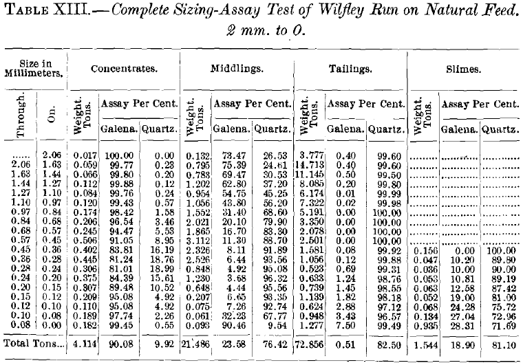
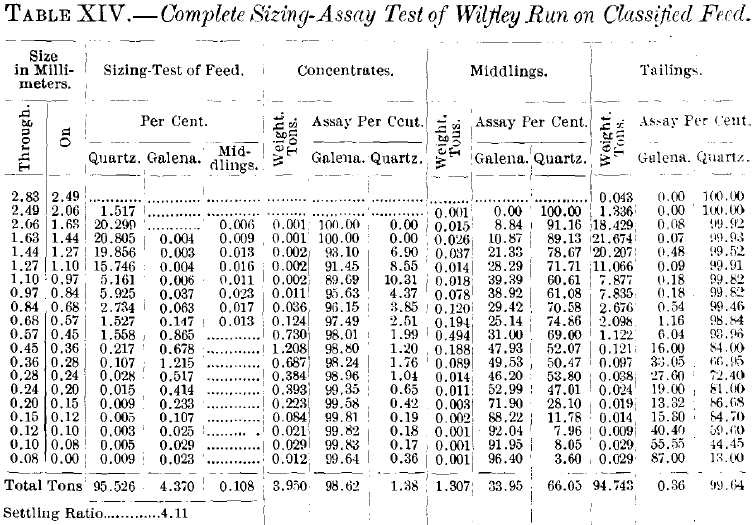
Table XIII., taken from the paper The Wilfley Table, shows the results of concentrating a hatch of ore with natural feed or mixed feed on a Wilfley table, and Table XIV. shows the results of feeding classified feed, second spigot of a free-settling classifier fed with from 2-mm. to 0 material, on a Wilfley table. The mixed feed gave for 100 tons of feed 4.1 tons concentrates with 90 per cent, of galena, 21.5 tons middlings with 23 per cent, of galena, and 72.8 tons tailings with 0.5 per cent, of galena. The classified feed gave 3.9 tons concentrates with 98 per cent, of galena, 1.3 tons middlings with 33 per cent, of galena, and 94.7 tons tailings with 0.36 per cent, of galena, showing a great improvement on all three lines above referred to. Tables XIII. and XIV. show many interesting facts, and a study of them will well repay the time spent.
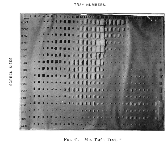
Tse’s Test.—Tse has demonstrated all the above points quantitatively. His test was to start the table, Fig. 40, working upon mixed feed of quartz and galena from 2.0 mm. to 0, and when running perfectly to slip in 30 little trays 1 in. wide in such position as to catch all the products except the finest slimes;
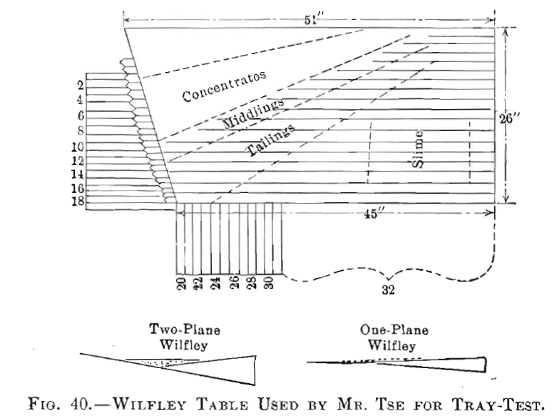
as soon as the trays were nearly full they were pulled out, and the time in seconds to make the catch noted. These 30 products were then sized on a series of sieves.
Trays 10,11 and 12, Fig. 41, are the middlings. In these we can readily see the coarse galena mixed with small quartz in sufficient quantity to bury the galena very nearly out of sight. Looking at the concentrates we do not see the small quartz, but it was found in considerable quantity and was bounded by the triangle whose angles are on the three heaps defined as follows:
1, tray 9, sieve 0.28; 2, tray 5, sieve 0.20; and 3, tray 9, sieve 0.12. The fine free mineral of the tailings is partly visible on the photograph. It is shown on line through sieve 0.08, from tray 13 to tray 24 or further.
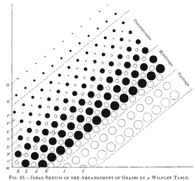
Mixed Feed for Wilfley Table.—By studying Fig. 42, which is constructed from Table XIII. and corroborated by Mr. Tse, and represents the bands of mineral grains where the table was fed with mixed feed, with the understanding that the line H represents the fine heavy mineral that washes over into the slime, the line G represents the fine free mineral that washes over into the middlings and tailings, we see that the following irregularities take place which need to be improved:
- The concentrates are contaminated by a noticeable amount of small free quartz grains.
- The middlings are large in quantity and they have large free mineral mixed with small free quartz and fine free mineral. Mr. Caetani has given the name “counterclassified” where the heavy mineral is in large grains and the quartz is in small grains.
- The tailings are contaminated with fine free mineral.
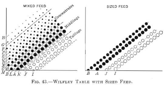
How Sized Feed Helps a Wilfley Table.—In the diagram, Fig. 43, we have placed the coarse quartz and the coarse galena just where they would be found in the mixed-feed bands of Fig. 42. The actual figures obtained, calculated for 100 tons of sized feed, gave 6.5 tons concentrates with 99 per cent, of galena, 1.6 tons middlings with 59 per cent. of galena, and 91.8 tons tailings with 0.04 per cent, of galena. It is not probable that the bands will stay so far apart as shown in the figure; in fact, they will run together a little. The small lot of middlings produced was 1.6 tons with 59 per cent, of galena, and these grains are perfectly separable on a Wilfley table. In consequence, the middlings can go to the little raff-wheel and be sent back into the feed without any harm whatever; they will not accumulate unless included grains or middle-weight mineral is present. Then different provision will have to be made. Summing up, we have:
The concentrates are free from small quartz; the middlings are small in quantity and can be fed over again unless included grains or middle-weight mineral is present; the tailings are free from fine free mineral. All of which is as satisfactory as possible.
How First Spigot of a Classifier Helps a Wilfley Table.—In the diagram, Fig. 44, we have placed the coarse quartz and the small galena, together with the added increment of larger
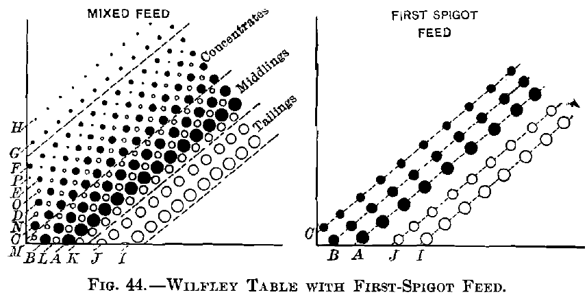
galena, approximately where they would be found in mixed- feed bands, see Fig. 42. If actually drawn to a scale the band of galena would be much wider than is shown in this diagram. The bands will not stay so far apart, but will mix a little. In my test, the middlings ran up to 5.5 tons in 100, but that I think is unnecessarily high. These middlings, unless included grains or middle-weight mineral is present, can be returned and fed over by raff-wheel and so save further complications. The actual figures obtained and rated for 100 tons of feed were: concentrates, 49.6 tons, with 99 per cent, of galena; middlings, 5.5 tons, with 13.8 per cent, of galena; and tailings, 44.8 tons, with 0.29 per cent, of galena, all of which is a thoroughly satisfactory improvement over mixed feed. The concentrates are free from quartz, the middlings are small in quantity, the tailings are practically free from fine free mineral.
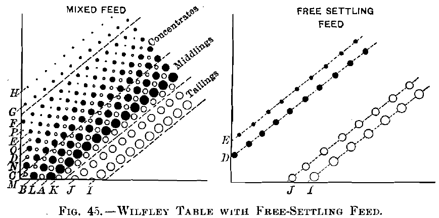
How Free-Settling Second Spigot Helps a Wilfley Table—Here, see Fig. 45, the bands are placed far apart, as they would be in the mixed-feed diagram. If actually drawn to scale they would be farther apart than as shown in this figure and the galena grains would be smaller relatively to the quartz. The actual figures obtained on basis of 100 tons were: concentrates, 3.9 tons, with 98.6 per cent, of galena; middlings, 1.3 tons, with 33.9 per cent, of galena; tailings, 94.7 tons, with 0.36 per cent, of galena. Here again the concentrates are practically free from small quartz, the middlings are small in quantity, and the tailings are almost free from fine free mineral.
If Table XIV. had been the result of hindered-settling classifier instead of free-settling classifier, the results and the above discussion would have shown still better.
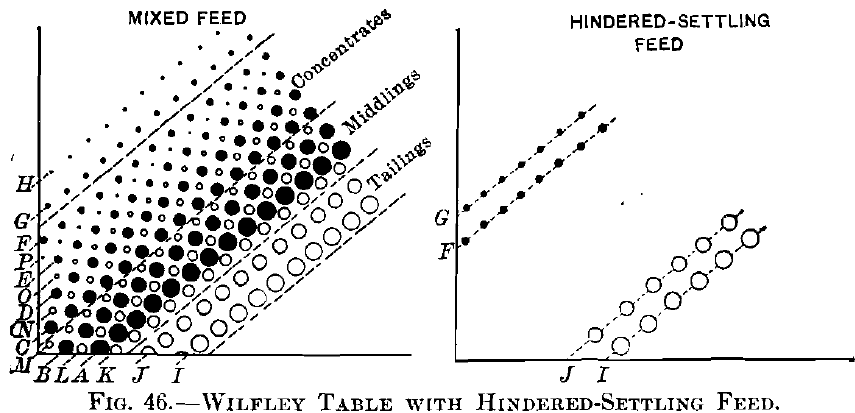
How Hindered-Settling Second Spigot Helps a Wilfley Table.— Fig. 46 represents the quartz and galena bands approximately as they would occur on the mixed-feed table. They are probably not far enough apart even here if drawn to scale. In actual work these will drift towards one another and be slightly mixed in the middlings, but the middlings can be fed back as in the previous cases and disappear from the account unless they are contaminated by included grains or middle-weight mineral, in which case they must receive suitable consideration, as in the previous cases also. (This calls for another paper.) My paper on The Wilfley Table has no instance in it of hindered-settling feed. (This also calls for another paper.)
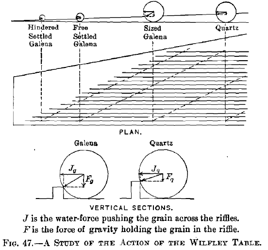
A Geometrical Suggestion.—When one watches the coarser tailings on the margin of the bands on a Wilfley table, and sees that the grains are jerked forward a little and then drop over a riffle-cleat, then jerked forward again and then drop over a riffle- cleat again, he is led to ask what is the determining feature which causes the grain to be lifted over the cleat. Fig. 47 is offered as a suggestion pointing to cause and effect. The large quartz grain has a short vertical arrow representing gravity, and a longer horizontal arrow representing the force of the water. Between these two forces lies the diagonal of the parallelogram which is the resultant of the two forces. The action would be as follows:
As soon as a point on the taper riffle-cleat was reached where the resultant came above the cleat, that moment the grain would rise over the cleat and drop into the next groove. This would be repeated over and over, and thus give the path of the quartz grain down a diagonal. The sphere of galena of the same size as the quartz would have a longer vertical arrow, and therefore its diagonal would reach lower, and therefore the riffle-cleat would have to be considerably lower before the point was reached where the galena grain could rise over and drop into the next groove. This gives the large grain of galena a diagonal path considerably in advance of the quartz. Again, a galena grain related in diameter to the quartz as in the second spigot of a free-settling classifier, that is, with a ratio of 1 to 3.5, would be far in advance again of the equal-sized grain of galena. Finally, a galena grain related in diameter to the quartz as in the second spigot of a hindered-settling classifier, that is, with a ratio of 1 to 6.9, would be still further in advance of the quartz. This cannot be regarded as a demonstration, because the grains in the figure are far too large to be true to nature, but if we consider that the vertical arrow represents the sum of all the forces that tend to keep the grain in the groove, and the horizontal arrow represents the sum of all the forces pushing the grain down the slope, then this analogy may turn out to be a true picture of fact.
What Can be Done to Improve Wilfley-Table Middlings resulting from mixed feed, supposing no preparatory classification or sizing is used? This product is “counter-classified” with grains of heavy mineral larger than the grains of quartz; see Fig. 41, trays 10, 11, and 12; also Fig. 42. This can be screened to let the small quartz and fine heavy mineral go through while the coarse heavy mineral remains on the screen as oversize; or better, it can be fed to a little free-settling classifier with one pocket. This would save more of the heavy mineral than the screen; or best of all, it could be fed to a one-pocket hindered-settling classifier, which would save more heavy mineral than the little free-settling classifier. The rejected fine product with either method could go to a Wilfley table to finish it.
What Can be Done to Improve Tailings of Wilfley Table resulting from mixed feed with no preparatory classification or sizing ? This product has included grains and fine free mineral. I am assuming that the slime has been already separated from it. This product is the exact opposite of the middlings. Free- settling classifier is better than hindered-settling, and screen- sizing is better than free-settling. The Callow screen seems to be the machine for this work. The oversize will be free
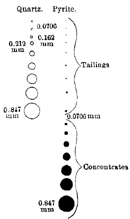
Fig.- 48 The Location of Loss by a Vanner
from fine free mineral and will in all probability be clean enough to throw away; if not, it must be crushed for included grains. The undersize can go direct to a vanner and yield clean concentrates and tailings. The slime can be sent to a vanner unless another slimer has been proved to be better.
Feed for Vanners:
What Can be Done to Improve Vanner-Tailings resulting from mixed feed without preparatory classification? A vanner-feed with pulp 0.847 mm. to 0, Fig. 48, will yield in the concentrates pyrite, 0.847 to 0.0706 mm. in diameter; and in the tailings, quartz, 0.847 mm. to 0, with pyrite, 0.0706 mm. to 0. This 0.0706 mm. is only the result of a single determination and needs to be corroborated, but it is believed to be about right. Here, as in Wilfley tailings, hindered-settling is not so good as free-settling, and free-settling is not so good as sizing for separating the fine from the coarse.
Hindered-settling would put into the overflow (multiplier is about 3):
Pyrite from………………………………………..0.0706 mm. to 0
Quartz from………………………………………..0.2118 mm. to 0
Free-settling would put into the overflow (multiplier is about 2.25):
Pyrite from………………………………………..0.0706 mm. to 0
Quartz from………………………………………..0.1588 mm. to 0
Screen-sizing would put into the undersize:
Pyrite from………………………………………..0.0706 mm. to 0
Quartz from………………………………………..0.0706 mm. to 0
Clearly the screen is theoretically the best, but the process would call for such a fine screen that it would, according to present knowledge, probably be impossible, and in consequence a free-settling classifier will probably be the best appliance to use here. The loss by included grains has not been considered, as the grains may be too fine for recrushing and redressing.
Having obtained the overflow or undersize, we next feed it upon canvas table, making clean tailings, and feed the canvas concentrate on a steep high-speed vanner, making clean concentrates, the tailings to go back to canvas.
Development of Hindered-Settling Apparatus, by ROBERT H. RICHARDS
