The below image shows a sectional view of a typical gyratory crusher. This type of machine is, by virtue of chronological priority, known as the “standard” gyratory crusher. Although it incorporates many refinements in design, it is fundamentally the same crusher that first bore the name of “gyratory”; its crushing chamber is very much the same shape; the motion is identically the same, and the method of transmitting power from belt to crushing head is similar. It is an interesting fact that the same similarity in essential features of design exists in the case of the “standard,” or Blake type, jaw crusher, which is something in the way of a tribute to the inspiration and mechanical ability of the men who originated these machines. 
Essentially, the gyratory crusher consists of a heavy cast-iron, or steel, frame which includes in its lower part an actuating mechanism (eccentric and driving gears), and in its upper part a cone-shaped crushing chamber, lined with wear-resisting plates (concaves). Spanning the crushing chamber across its top is a steady-rest (spider), containing a machined journal which fixes the position of the upper end of the main shaft. The active crushing member consists of the main shaft and its crushing head, or head center and mantle. This assembly is suspended in the spider journal by means of a heavy nut which, in all but the very large machines, is arranged for a certain amount of vertical adjustment of the shaft and head. At its lower end the main shaft passes through the babbitted eccentric journal, which offsets the lower end of the shaft with respect to the centerline of the crusher. 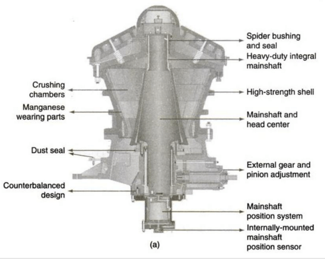 Thus, when the eccentric is rotated by its gear train, the lower end of the main shaft is caused to gyrate (oscillate in a small circular path), and the crushing head, likewise, gyrates within the crushing chamber, progressively approaching, and receding from, each element of the cone-shaped inner surface.
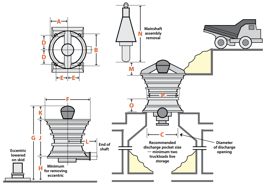
The action of the gyratory crusher, and of the other member of the reciprocating pressure family, the jaw crusher, is fundamentally a simple one, but as will be seen a great deal of thought and some very progressive engineering has been expended upon the design of crushing chambers to increase capacities and to permit the use of closer discharge settings for secondary and fine-reduction crushing (various crusher types).
Referring to the table, always available from the manufacturer, it will be noted that standard gyratory crushers are manufactured in commercial sizes ranging from 8″ to 60″ receiving openings. Capacities are listed, for minimum and maximum open-side discharge settings, in short tons per hour, and the horsepower requirements for soft and hard materials are listed for each size. The capacities, and the minimum settings, are based upon the use of standard (straight-face) concaves.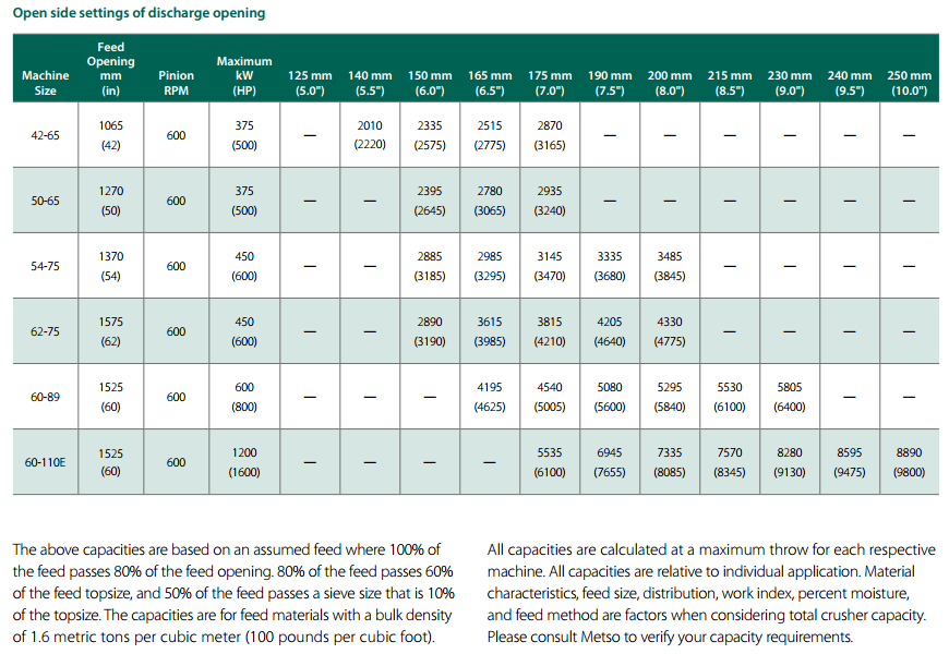
Primary gyratory crushers are designated by two numbers. These are the size of the feed opening (in inches) and the diameter of the mantle at its base (in inches). A 60″~x~89″ crusher would have an opening dimension of 60 inches (152 cm) and a diameter across the base of the mantle of 89 inches (226 cm).
To stand up under the extremely rugged work of reducing hard and tough rock and ore, and in doing so to maintain reasonably true alignment of its running component, the crusher must necessarily be of massive and rigid proportions, rigidity being of equal importance to ultimate strength. Regardless of the tensile strength of the metal used in the main frame, top shell, and spider, these parts must be made with walls and ribs thick enough to provide this rigidity. Therefore it is practicable to use close-grained cast iron, and special high-test mixtures of cast iron, for these parts, if the machine is intended for crushing soft or medium materials. When very hard and tough materials are to be crushed, the machine is usually strengthened by substituting cast steel in one or more of its parts.
Wearing parts in the gyratory crusher may be either chilled cast iron or manganese steel, depending on the character of the material to be crushed and the particular class of service for which the machine is intended. Standard crushers, in the small and medium sizes, are customarily fitted with chilled-iron head and concaves for crushing soft and medium limestone and materials of similar hardness and abrasiveness, because its relatively low first cost and excellent wearing qualities make it the most economical material to use when the service is not too severe. Manganese steel, which combines extreme toughness with unsurpassed wear-resistance, is the universal choice for crushing hard, tough rock regardless of the class of service or type of crusher. Even though the rock be quite soft and non-abrasive, it is general practice to use manganese steel concaves in the larger sizes of primary crushers because of the shocks attendant upon handling large and heavy pieces of rock.
Gyratory Crushers
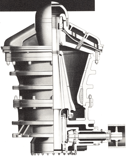
The primary rock breaker most commonly used in large plants is the gyratory crusher, of which a typical section is shown in Fig. 5. It consists essentially of a gyrating crushing head (521) working inside a crushing bowl (522) which is fixed to the frame (501).
The crushing head is carried on a short solid main shaft (515) suspended from the spider (502) by a nut (513) ; the nut fits into the seating of a sleeve (514) which fixes its position in relation to the spider and, therefore, to the frame (501). The lower part of the main shaft fits into a sleeve (530) set in an eccentric (527), to which is keyed the bevel driving gear (528) ; the bevel pinion (533) is similarly fastened to the countershaft (535) and engages with the bevel gear. The whole of this driving assembly is protected from grit and dust by means of a dust seal (524), (525), and (526).
The countershaft carries the driving pulley, and as it revolves it causes the eccentric to rotate ; as it rotates the main shaft gyrates and with it the crushing head ; the top of the shaft at the point of suspension has practically no movement. Although the motion of the head is gyratory, the main shaft is free to rotate in the eccentric and it actually revolves slowly in relation to the bowl, thus equalizing the wear on the mantle (519) which lines the head and on the concave liners (522 and 523) which comprise the bowl. Both mantle and bowl liners are usually made of manganese steel. The suspension nut (513) is adjustable and enables the crushing head and main shaft to be raised in relation to the bowl to compensate for wear. The size of the product is determined by the distance between the bottom edges of the crushing head and the bowl, in the position when they are farthest apart.
The crushing action is much the same in principle as that of a jaw crusher, the lumps of ore being pinched and broken between the crushing head and the bowl instead of between two jaws. The main point of difference between the two types is that the gyratory crusher does effective work during the whole of the travel of the head, whereas the other only crushes during the forward stroke. The gyratory crusher is therefore the more efficient machine, provided that the bowl can be kept full, a condition which is, as a rule, easy to maintain because it is quite safe to bury the head in a pile of ore.
Gyratory Crusher Capacity Tables


Tables 7 and 8 give particulars of different sizes of gyratory crushers. As in the previous paragraph, the capacity figures are based on material weighing 100 lb. per cubic foot and should be increased in direct proportion for heavier ores.
Small Gyratory Crusher Capacity Chart

Crusher Drive
Primary and secondary gyratory crushers, including the cone crusher, can be directly connected to slow speed motors if desired, but the standard method of drive is still by belt and pulley. Jaw crushers must be belt-driven.
An efficient substitute for the flat belt in all cases is the Texrope drive, which consists of a number of V-shaped endless rubber belts running on special grooved pulleys. The grip of these belts is so great that the distance between the pulley centres can be reduced to about 30% of that required for a flat belt. This results not only in a saving of space but also in greater safety, since the drive is easier to protect and there is no danger of an accident such as might occur if a long belt were to pull through its fasteners. Moreover, the short drive makes it possible for any stretch to be taken up by moving the motor back on its rails without the necessity of cutting and rejoining the belts. The flexibility and ease of maintenance of the Tex-rope drive makes it very suitable for crushing machines.
Gyratory Crusher
MAXIMUM STRENGTH Sturdy all-steel construction. Heavy external ribs.
HIGH CAPACITY Large head diameter, balanced relationship between speed and eccentric throw, long, deep, properly curved crushing chamber. Bottom discharge speeds run-off.
LOW OPERATING COSTS Vertical adjustment compensates for wear on crushing surfaces (also maintains product uniformity). Oiling system provides proper lubrication throughout, including spider. Effective dust seal prevents dust infiltration to moving parts. Long life bearings, easy to replace.
These and many more important features contribute to the unparalleled performance of the Gyratory crusher.
 HIGH STRENGTH
Strength, of course, makes an all-important contribution to the rugged heavy duty service and day-in, day-out dependability demanded of a crusher. However, strength does not necessarily mean excessive weight. The metals and alloys used in construction and the distribution of weight are actually the determining factors in the strength of a gyratory crusher.
HIGH TENSILE METALS PROVIDE HIGH RATIO OF STRENGTH TO WEIGHT
In the Gyratory crusher, the spider, top shell and bottom are shock-resistant cast steel. Annealed forged steel is used in the mainshaft. The spiral bevel gear and pinion are heat-treated alloy steel.
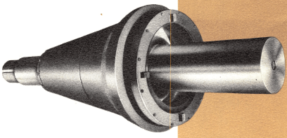
MAINSHAFT ASSEMBLY mainshaft forged steel; annealed quenched and tempered. Tapered to gauge for head center fit. Head center of cast steel. Head mantle of manganese steel. Mainshaft sleeve shrunk on mainshaft to provide renewable wearing surface on spider bearing.
PROPERLY PLACED RIBS ADD STRENGTH, MINIMIZE WEIGHT
Gyratory crusher advanced design includes the placing of circumferential ribs around the top and bottom shells. These integrally cast reinforcing rings prevent distortion provide the rigidity necessary to maintain true alignment of running parts.
SPIDER DESIGNED FOR MAXIMUM RIGIDITY AND STABILITY
Hollow box construction of the cast steel spider affords maximum strength with the least amount of feed interference. Arms are cast integrally with the heavy outer rim. Crushing stresses are transmitted to the rim, which is taper-fitted to the top shell. Because spider and top shell are interlocked, they reinforce each other to provide maximum stability and rigidity.
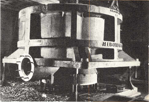
BOTTOM SHELL The eccentric bearing hub is cast integral with shell. Hub is machined for eccentric bushing fit, faced for bottom plate and machined for pinionshaft housing.
POUND OF METAL RESISTS CRUSHING STRESSES
COMPACT BOTTOM SHELL PROVIDES STURDY BASE, PROTECTS VITAL MECHANISM
The bottom shell is the foundation of the crusher. It must be strong enough not only to support the weight of the crusher, but to withstand extreme crushing stresses (most stresses terminate here) strong enough to protect vital mechanism — the eccentric, gears and countershaft assembly housed in the bottom shell. In the Gyratory crusher, bottom discharge design makes possible a compact, squat structure of simplified design and comparatively high strength. Supplementing the strength of the bottom shell are the previously described circumferential ribs. Crushing stresses are transmitted directly to these reinforcing members through three radial arms.
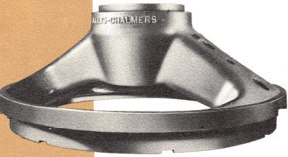
SPIDER cast steel two-arm type. Spider arms and rim protected with liners of manganese steel or cast steel, depending upon the application.
STUBBY MAINSHAFT WITHSTANDS SEVERE SERVICE
Because the mainshaft does the actual crushing, it must literally possess “crushing strength.” In the Gyratory crusher, the eccentric is located directly below the crushing head. This design permits the use of a short, rigid mainshaft a mainshaft that will withstand the strain of severe service.
TOP SHELL constructed of cast steel. Inside finished for concaves. Note tapered fit for spider. On larger crushers top shell may be split horizontally to facilitate shipping.
ADAPTABILITY
Flexibility is the keynote of the Gyratory crusher efficiency and economy. While your particular installation is designed to best meet your specific and immediate requirements, built-in flexibility permits adaptation to changing operating conditions anytime in the future.
A Gyratory crusher not only affords a maximum capacity-to-size ratio, but provides the variable factors which facilitate increasing or decreasing capacity as the need arises. Flexibility in a Gyratory crusher also permits compensation for wear and assures product uniformity.
SPEED ADJUSTABLE TO CAPACITY DEMANDS
In the Gyratory crusher, the use of spiral bevel gears instead of spur gears makes possible the broad range of speeds conducive to meeting varying capacity demands. Because the Gyratory crusher is equipped with an external oiling system, speed may be reduced as much as desired or required. Adequate lubrication is supplied at even the lowest speeds, because the flow of oil is not relative to the crusher’s operating speed as is the case with an internal system.

MEETING BROAD RANGE OF OPERATING CONDITIONS
PINIONSHAFT ASSEMBLY for a 42-65 Gyratory crusher. Spiral bevel pinion mounted on turned steel shaft in cast steel housing. Anti-friction bearings.

Assembly is independently lubricated. Seal plates and oil seals on both ends of housing. Spiral bevel gears allow a broad range of speeds.
Eccentricity Adjustable to Capacity Demands
With a primary gyratory crusher running at a given countershaft speed, capacity is increased as eccentricity is increased. At a given eccentricity, greater capacity results from higher countershaft speeds. Conversely, reducing either the speed or eccentricity reduces capacity.
Eccentricity, in a Gyratory crusher, may be varied by simply installing the proper sleeve in the eccentric at the bottom of the mainshaft.
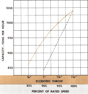
Relationship of crusher capacity to eccentricity and speed for a 42-65 Gyratory primary with 6-inch open side setting. Capacity is in tons per hour of 100 lb per cubic foot crushed material.

ECCENTRIC ASSEMBLY for a 48-74 Gyratory crusher, showing spiral bevel gear, cast steel eccentric and bronze eccentric sleeve. Also note oil groove and passage through top of sleeve and eccentric.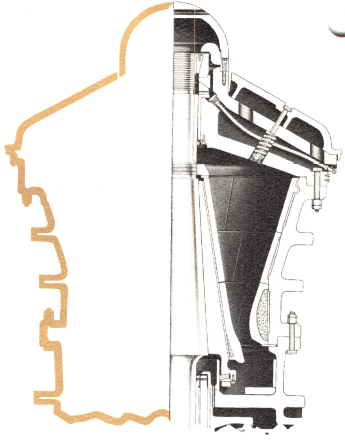
Gyratory motion is imparted to the mainshaft by means of the eccentric at the lower end of the mainshaft. The spiral bevel gear and pinion transmit power to the eccentric from the countershaft.
CRUSHING CHAMBER DESIGNED FOR HIGH CAPACITY
The Gyratory crusher features a long, deep, curved profile crushing chamber with an acute crushing angle. This design provides a positive breaking action and minimizes slippage.
Another high capacity characteristic of the Gyratory crusher is a large diameter crushing head. Because the area of discharge opening is directly proportionate to head diameter, high capacities result.
DEEP, CURVED CRUSHING CHAMBER minimizes slippage, provides acute crushing angle maximum capacity.
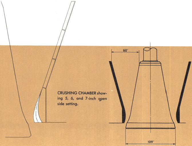
VARIABLE INITIAL SETTINGS The contour of the crushing chamber at the bottom is designed to afford various initial settings without changing the angle of the nip. This is accomplished by installing lower tier concaves of the shape and thickness for the desired setting and capacity.
 HOW SIZES ARE DESIGNATED The numerical size designation of Gyratory crushers represents the feed opening and the maximum diameter of the crushing head. For example, a 60-109 Gyratory crusher has a 60-inch receiving opening and an 109-inch maximum diameter crushing head.
ADVANTAGES OF BOTTOM DISCHARGE
ELIMINATES DIAPHRAGM In a gyratory crusher with a side discharge, sticky materials may pack on the diaphragm and eventually cause considerable damage. The straight down discharge of the Gyratory crusher is a design simplification that eliminates the diaphragm and its maintenance problems.
REDUCES Weight Because of the bottom discharge design, the bottom shell has been shortened. Crusher weight has been reduced considerably without sacrificing strength.
CONTRIBUTES TO BALANCED CIRCUIT The adaptability of a primary crusher to a large extent dictates the plant flowsheet — the initial and overall operating costs of subsequent equipment. With a Gyratory primary crusher, these costs are kept at a minimum because the entire crushing circuit remains in balance. The concrete foundation may be modified for use as a surge bin. This storage capacity permits controlling the flow of material through the plant. Secondary and tertiary crushers, vibrating
screens, etc. may be installed in size ranges and types to meet the requirements of a constant tonnage. For those few installations where a side discharge is essential, a discharge spout can be furnished. Another factor in maintaining a balanced circuit is the vertical adjustment (pages 12 and 13) which permits retaining the initial discharge setting by compensating for wear on mantle and concaves. Related equipment need not be readjusted because of variations of feed size from the primary crusher.

LOW OPERATING COSTS VERTICAL ADJUSTMENTS
In the Gyratory crusher, the original discharge setting may be maintained for the life of a single set of alloy crushing surfaces with only one resetting of concaves. Raising the mainshaft compensates for wear on concaves and mantle. This simplified vertical adjustment cuts resetting time — facilitates holding product size.
METHODS OF VERTICAL ADJUSTMENT
In the Gyratory crusher, vertical adjustment is provided for in a choice of two methods — spider suspension of mainshaft and the Hydroset mechanism.
Gyratory Crusher Spider suspension
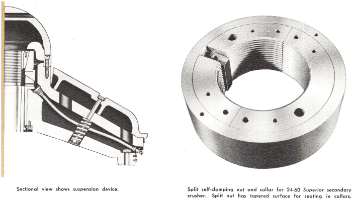
The threaded mainshaft is held in and supported from the spider hub. (See illustration at lower left.) A vertical adjustment range of from 6 inches to approximately 11 inches is possible, depending upon the size of the machine. The original discharge setting can be maintained until the combined wear of mantle and concaves is about one-third of the vertical adjustment.
A cast steel, split adjusting nut with a collar is supported on a two-piece thrust bearing in the spider hub. The nut is threaded for the mainshaft. The outside of the nut is tapered, with the large diameter at the top. The weight of the head and shaft draws the nut down in its tapered seat in the collar to form a self-clamping nut. Desired setting is achieved by positioning split nut in the proper location on the threaded portion of the mainshaft.
OF MAINSHAFT COMPENSATES FOR WEAR
Hydroset mechanism
The Gyratory crusher is also available with a Hydroset mechanism a hydraulic method of vertical adjustment. With the Hydroset mechanism, compensation for wear and product size control is a one- man, one-minute operation. The Hydroset mechanism consists of a motor-driven gear pump operated by push button.
The accompanying drawings show the simplicity of Hydroset design. The mainshaft assembly is supported on a hydraulic jack. When oil is pumped into the jack, the mainshaft is raised compensating for mantle and concave wear or providing a closer setting. When oil is removed from jack, the mainshaft is lowered and a coarser setting results.
Since the mainshaft assembly is supported on a hydraulic jack, its position with respect to the concaves, and therefore the crusher setting, is controlled by the amount of oil in the hydraulic cylinder.
INDEPENDENT HYDRAULIC OIL SYSTEM
Oil pressure is maintained in the hydraulic cylinder below the mainshaft by a highly effective chevron packing. The oil supply of the Hydroset mechanism functions independently of the crusher’s lubrication system.
EASY-TO-CLEAN CRUSHING CHAMBER
If a Gyratory crusher equipped with Hydroset mechanism stops under load, the mainshaft may be lowered to facilitate clearing of the crushing chamber by merely pumping oil out of the cylinder. Only under extreme conditions is it necessary to “dig out.” When the cause of the stoppage is remedied, the oil is pumped back into the cylinder quickly, returning the mainshaft assembly to its initial position.


STEP BEARING consists of bronze mainshaft step, bronze piston wearing plate, and an alloy steel washer between the two. Washer is drilled for oil cooling lubrication. Bearing surfaces are grooved to permit oil distribution.
Gyratory SPIDER LUBRICATION
Utilizing pool lubrication, a gun-type fitting in the spider arm makes it easy to oil the spider bearing. A garter-type oil seal in the bottom of the bearing retains oil. Being flexible, the seal compensates for movement of crusher mainshaft.

COUNTERSHAFT BEARING LUBRICATION
The countershaft assembly is an anti-friction, pool-lubricated unit. Both ends of the bearing housing are sealed by garter-type spring oil seals which: (1) keep dust from anti-friction bearings; (2) separate pinion- shaft bearing lubricant from oil lubricating the eccentric and gears.

The colored line indicates flow of oil to all critical wearing parts. The separately lubricated countershaft assembly can be removed from the crusher for convenient cleaning and repairing.
POSITIVE LUBRICATION
Getting the most out of a crusher in performance and capacity depends largely upon positive lubrication. And positive lubrication means more than just adequate oil lubrication. It also entails conditioning oil for maximum lubricating efficiency.
INDEPENDENTLY CONTROLLED NOT DEPENDENT ON CRUSHER SPEED
The Gyratory crusher is equipped with an externally located, fully automatic lubricating system.
Positive and constant lubrication is maintained at all speeds — even at the slowest speed. If desired, oil may be circulated through bearings of Gyratory crusher during shutdown periods.
HOW a GYRATORY CRUSHER IS LUBRICATED
A gear pump circulates oil from storage tank, through crusher and back. Each time oil is pumped to the crusher, it passes through the filter and cooler. The cleaned, cool oil lubricates the step bearing (in Hydroset mechanism only), the eccentric wearing plate and the inner eccentric bearing. At the top of the bearing, most of the oil flows through ports in the eccentric to the outer eccentric bearing. The oil then flows down the outer eccentric bearing and lubricates the gear and pinion before it is returned to storage. The overflow oil which may have become contaminated is returned immediately to the oil conditioning tank. It does not contact any other wearing parts within the crusher.
The spider and countershaft bearings are lubricated separately.
SYSTEM MODIFICATIONS
The oil conditioning system may be modified to meet your particular applications.
In cold climates immersion heaters are installed in the storage tank to preheat oil. This arrangement permits circulating warm oil through the crusher during shutdown periods. A thermostatic control turns heater on and off. Only in a crusher specifically designed for external oiling is it possible to circulate warm oil when the crusher is stopped.
Another modification is a radiator for air cooling oil. The radiator is used in oil conditioning systems for crushers installed in areas where cooling water is not available.
SYSTEM FILTERS AND COOLS OIL 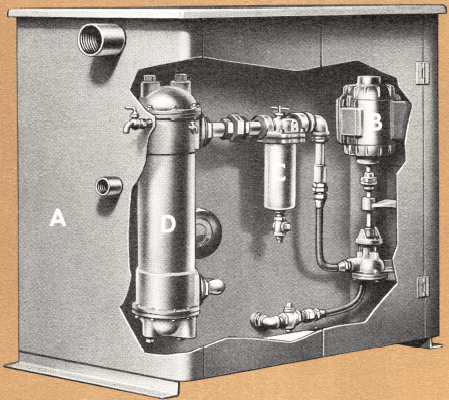
An added measure of safety is provided by the oil conditioning system. Foreign material is removed by pumping warm oil through a mechanical filter. After oil is filtered, it flows through a condenser-type
cooler before it is returned to the crusher.
AUTOMATIC SAFETY SWITCH PREVENTS DAMAGE
An oil flow switch provides automatic protection against possible damage caused by oil system failure. This switch stops the crusher immediately if oil flow is insufficient for proper lubrication. Interlocks between pump motor and crusher prevent starting crusher before oil circulation begins.
In addition to its other advantages, the externally located oil conditioning system is easy to service. The unit consists of (A) an oil storage tank, (B) a motor-driven gear pump, (C) a pressure- type filter, and (D) a condenser-type cooler.
EASILY ACCESSIBLE, RENEWABLE PARTS TAKE WEAR
In the gyratory crusher, expensive castings are protected by replaceable parts. Rim and arm liners protect the spider from wear. Bottom shell liners and shields provide protection below the crushing chamber. An alloy steel shaft sleeve protects the mainshaft in the spider bearing. The eccentric sleeve and bushing are easily replaced when worn.
Because all parts are readily accessible and removable, down time is kept to a minimum. For example, the countershaft assembly is removed as a unit and can be taken to your machine shop for convenient servicing. Eccentric bearings are bronze bushings. Because bronze is used, the need for babbitt mandrels and melting facilities is eliminated.
DUST PROTECTION
Sealing out dirt and dust and their equipment-destroying abrasive action results in obvious maintenance economies. The type of dust seal used in the gyratory crusher is the most reliable and effective device ever developed for preventing excessive wear caused by dirt and dust.
HOW THE DUST SEAL WORKS
In the gyratory crusher, a synthetic, self-lubricating, light-weight ring is used as a dust seal. The ring is enclosed between a dust collar bolted to the bottom shell and a recess in the bottom of the head center. Regardless of the eccentric throw and vertical positioning, the ring maintains its contact with the outer periphery of the dust collar. Because of its light weight and self-lubricating characteristics, wear on this ring is negligible.
Protection for Crushers In Abrasive Conditions
Provisions have been made on the gyratory crusher for the introduction of low pressure air to the dust seal chamber. This internal pressure, which can be obtained through the use of a small low pressure blower, creates an outward flow of air through the dust seal. This prevents an inward flow of abrasive dirt and dust. The combination of a highly effective sealing ring and the utilization of internal air pressure protects the eccentric and gears from destructive infiltration even under the most severe conditions. When required, this additional protection is supplied at a nominal additional cost.

Close-up of dust seal on 30-55 mainshaft assembly. Note scrapers on underside of retaining ring. These scrapers prevent material build-up on arms of bottom shell.

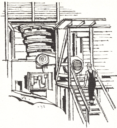 All of the operating advantages all of the engineering and construction features described in this bulletin are found in both the primary and secondary gyratory crushers. Of course, certain modifications have been made to efficiently accomplish the tough, rugged job of secondary crushing. For instance, the secondary gyratory crusher has been engineered to accommodate the greater horsepower requirement of secondary crushing. Increased strength and durability have been built into all components.
DESIGN FEATURES
In the past, primary crushers had to be set extremely close in order to provide an acceptable feed for secondary crushers. As a result, primary crushers were penalized by reduced capacity and excessive maintenance. The secondary gyratory crusher was engineered to solve this problem.
Anticipating product size variations, Allis-Chalmers has designed the secondary crusher with a large feed opening one large enough to accept oversized materials. This design feature is particularly advantageous when the secondary gyratory crusher follows a primary crusher that has no vertical adjustment for wear.
A large diameter crushing head along with tailored-to-your-operation design results in big capacity. An acute angle in the crushing chamber and a long parallel zone facilitate precision setting assure a cubical, well graded product distributes even the normal wear throughout the crushing chamber.
Gyratory Crusher Sections
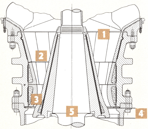
1 Big Feed Opening reduces possibility of bridging by oversized material.
2-3 Acute Angle in Crushing Chamber and Long Parallel Zone permits fine setting necessary for secondary crushing.
4 Vertical Adjustment makes possible maintaining fine settings for long periods. With the Hydroset mechanism, vertical adjustment is a one-man, one-minute operation.
5 Large Diameter Crushing Head plus the flexibility in the initial setting, eccentric throw and operating speed makes possible crusher adaptation to desired capacity and product size.
Gyratory Crusher Parts


PART NO. NAME OF PART
1. Spider cap
2. Spider
3. Hour glass bushing
4. Spider bearing oil seal
5. Spider bearing oil seal retainer
6. Spider bearing oil seal retainer screws
7. Spider joint bolts
8. Spider joint bolt nuts
9. Spider joint bolt lock nuts
10. Spider arm shield
11. Spider arm shield bolts
12. Spider arm shield bolt nuts
13. Center spider rim liners (not shown)
14. End spider rim liners
15. Rim liner bolts
16. Rim liner bolt nuts
17. Spider bearing spherical support ring
18. Spider bearing spherical support ring seat
19. Spider lubricating hose bushing
20. Spider lubricating hose
21. Spider lubricating hose bracket
22. Spider lubricating hose grease fitting
23. Spider lubricating hose bracket bolts
24. Spider joint studs (not shown)
26. Mainshaft thrust ring
27. Mainshaft thrust ring bolts
31. Top shell
32. Concave support ring
33. Upper concaves
34. Upper middle concaves
36. Lower middle concaves
37. Lower concaves
43. Bottom shell
44. Bottom shell joint bolts
45. Bottom shell joint bolt nuts
46. Bottom shell joint bolt lock nuts
47. Bottom shell bushing
48. Bottom shell bushing key
49. Bottom shell bushing clamp plate
50. Bottom shell bushing clamp plate bolts
51. Bottom shell front arm liners
52. Bottom shell rear arm liners
53. Bottom shell side liners
54. Bottom shell hub liners
55. Dust collar
56. Dust collar cap screws
57. Dust collar gasket
63. Bottom plate
64. Bottom plate studs
65. Bottom plate stud nuts
66. Bottom plate stud lock nuts
67. Bottom plate dowel pin
68. Bottom plate drain plug
69. Bottom plate gasket
95. Eccentric
96. Eccentric sleeve
97. Eccentric sleeve key
98. Bevel gear
99. Bevel gear key
100. Bevel gear key cap screws
101. Eccentric wearing plate
107. Mainshaft
108. Head center
109. Mantle lower section
110. Mantle upper section
111. Head nut
112. Dowel pin (for keying head nut to mantle)
113. Mainshaft sleeve
114. Adjusting nut
115. Adjusting nut collar
116. Enclosed ring type dust seal sealing ring
117. Enclosed ring type dust seal retaining ring
118. Enclosed ring type dust seal bolts
119. Adjusting nut tie bar
120. Adjusting nut tie bar bolts
121. Adjusting nut key
124. Pinion bearing housing
125. Pinion bearing housing gasket
126. Pinion bearing housing studs
127. Pinion bearing housing stud nuts
128. Pinion bearing housing stud lock nuts
129. Pinion bearing housing dowel pin
130. Pinion bearing housing oil drain plug
131. Pinion bearing housing oil level plug (not shown)
132. Pinion bearing housing oil filler plug
133. Pinionshaft
134. Drive sheave and bushing
135. Drive sheave key
136. Pinion shaft lock nut spacer
137. Pinion shaft lock nut spacer lockwasher
138. Pinion shaft lock nut spacer lockwasher gasket
139. Pinion bearing seal plate
140. Pinion bearing oil seal
141. Pinion bearing seal plate gaskets
142. Pinion bearing seal plate bolts
143. Pinionshaft outer bearing
144. Pinionshaft inner bearing
145. Pinionshaft bearing spacing collar
146. Pinionshaft bearing spacing collar gasket
147. Pinion
148. Pinion key
149. Pinion retainer plate
150. Pinion retainer plate bolts
GYRATORY CRUSHER DIMENSIONS
Tabulated drawings on this page show the principal dimensions of the gyratory crusher. These dimensions are sufficiently accurate for preliminary plant layout work.

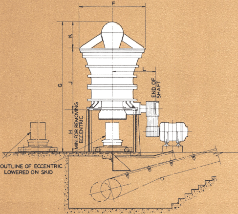

GYRATORY CRUSHER INSTALLATION DRAWING


In the dimension charts above, the first number in each size classification designates the size of the receiving opening in inches. The second number is the largest diameter of the mantle in inches. Primary crushers having the same mantle diameter use the same size bottom shell, gears, eccentrics and countershaft assemblies.
Secondary crushers use the same size bottom shells as certain size primary crushers, but different size top shells, mainshaft and spider assemblies. The 30-70 secondary gyratory crusher uses the bottom shell of the 42-65 primary crusher; the 24-60 secondary uses the 30-55 primary bottom shell.

PERFORMANCE TABLE
CAPACITIES OF GYRATORY CRUSHERS
IN TONS PER HOUR (2000 LB TON) BASED ON 100 LB PER CU FT CRUSHED MATERIAL.


Capacities given here are based on field data under average quarry conditions when crushing dry friable material equivalent to limestone. Because conditions of stone and methods of operation vary, capacities given are approximate only.
Where no capacity data is given the crusher is under development. Figures under Maximum Horsepower are correct only for throw and pinion Rpm given above. When speed is reduced, Maximum Horsepower must also be reduced proportionately.
Example: 42-65 crusher, 1 inch throw, 265 Hp at 497 Rpm.
At 400 Rpm Maximum Hp = 265 x 400/497 = 213
Crusher Feed Opening To Power Shovel Dipper
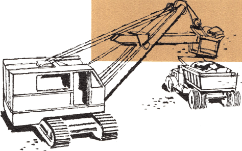

CRUSHER FEED OPENING
This graph is based on customary practice and is principally a guide. Size of crusher may vary considerably with different materials, depending upon stratification, blockiness, quarry methods and size of quarry trucks. Pieces that cannot be handled by crusher without bridging should be broken in the quarry.
Gyratory Product Analysis and Product Curve
Selecting the type of material and type of feed determines the percent of product passing a square opening equal to open side of the crusher.

PRIMARY Gyratory CRUSHER
The screen analysis of the product from any crusher will vary widely, depending upon the character of the material, quarry conditions, and the amount of fines or product size in the initial feed at the time
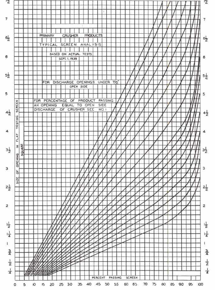
TABLE 2
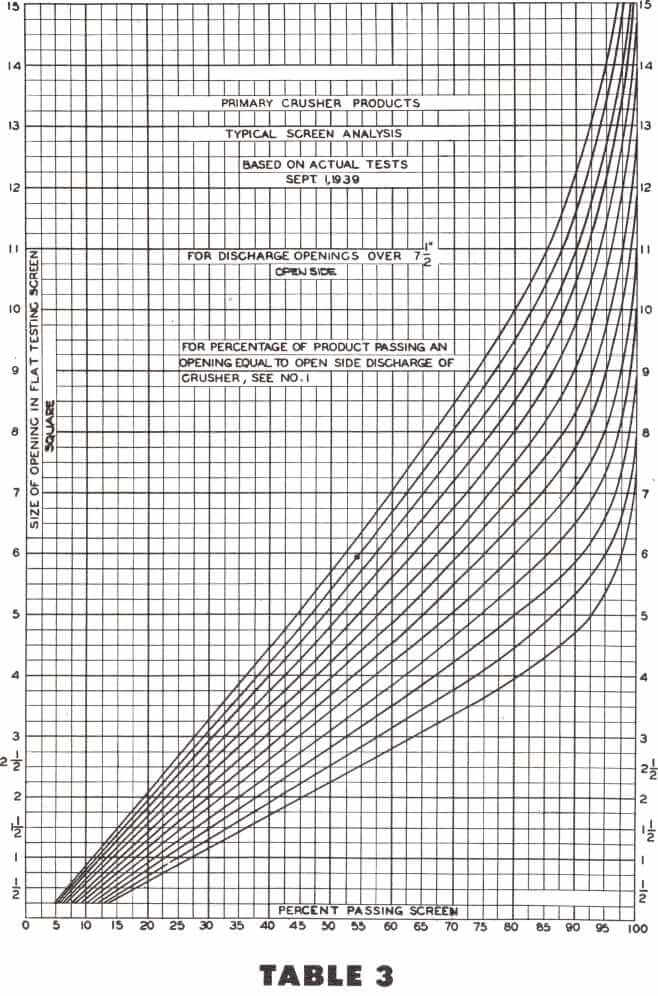
the sample is taken. These factors should be taken into consideration when estimating the screen analysis of the crusher product. Product gradation curves based on many actual screen analyses have been prepared which can be used for estimating.
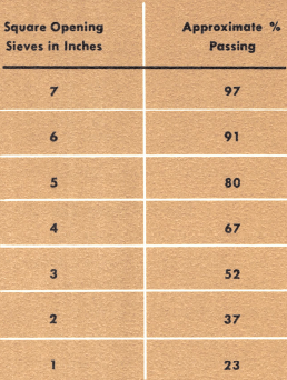
The crusher discharge opening on the open side will govern the product gradation from a crusher if corrected to take into consideration quarry or mine conditions, particularly as to the amount of fines in the crusher feed. The tabulation at the left is based on an average of many screen analyses and gives the approximate percentage of product equal to the open side setting of the crusher. Its actual use when the feed conditions are definitely known should be corrected to take care of these conditions, particularly insofar as fines or product size in the feed are concerned. The curves on these pages have been prepared giving the approximate screen analysis of the crusher product and should be used in conjunction with Table I
EXAMPLE
Feed — Run of quarry medium hard limestone including fines to 42-65 gyratory crusher set 6 inches open side.
Table I shows 90% of product should pass a 6-inch square opening flat testing sieve. Using the 90% vertical line on Table II, follow it up to the horizontal line of 6 inches. Follow the nearest curve to the intersection, and using this curve you will get the following approximate screen analysis.
Formula for Determining Horsepower Requirements
Until recently, there has been no way of accurately determining the power required for a given crushing operation. With little or no factual operating data correlated into useful form, it was difficult even for the most experienced operators to arrive at a correct size crusher or a proper size crusher motor to do a given job.
To overcome these costly shortcomings, Allis-Chalmers compiled and correlated the factual data developed from actual tests and experience obtained over a period of more than 35 years.
The correlation of all this factual material, from extensive field operating data and laboratory data covering wide varieties of material, ranges of reduction sizes, and types of equipment, made it possible to establish a consistent common factor known as the Work Index for accurately determining the power required for crushing.
In the Work Index method, frequently referred to as the Bond method, the Work Index is actually the total work input in kwhr per short ton required to reduce a given material from theoretically infinite particle size to 80% passing 100 microns or approximately 67% passing 200 mesh. Knowing the Work Index, you need only apply the given equation to determine power input required. The calculated power input enables you to select the proper crusher.
In order to simplify the selection of a crusher by the Work Index method, the following form has been developed. References below the form explain the various parts of the calculation, and, immediately below, a complete example is worked out.
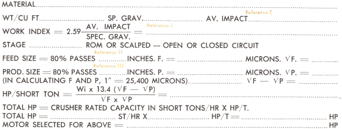
REFERENCE I Average Impact. As noted, the Work Index is determined from the average impact value and the specific gravity of the material being crushed. The impact value and Work Index can be determined in the Processing Machinery Laboratory, or these values can be determined from a comparable operation in the field. A complete listing of Work Indexes of materials which have been tested in the laboratory.
REFERENCE II Feed Size. In the case of a primary crusher this may be somewhat difficult to obtain. Experience indicates, however, that in most cases 80% of the feed size will pass a square opening equal to from half to two-thirds of the crusher receiving opening.
REFERENCE III Product Size. This can be determined with reasonable accuracy from the crusher product curves given on here.
The Following Example Illustrates the Application of the Above Calculations to a Specific Problem:
A crushed stone producer desires a primary crusher to handle the product from a 3-yard shovel at an average rate of 350 tph. The rated capacity of the crusher must, of course, be greater than this because of inevitable quarrying and crushing delays. A crusher setting of 5 in. on the open side is desired because of following equipment and the requirements for stone.
A Processing Machinery Laboratory test indicates the limestone has an impact value of 10.8 ft-lb/in. and a specific gravity of 2.60. The Work Index is, therefore, 10.7 (see Reference I above).
MATERIAL: Limestone WORK INDEX —10.7
CRUSHER: 42-65 Primary gyratory
Open Side Setting: 5″; Eccentric Throw: 1″
Recommended Operating Speed; 400 Rpm
(Approximately 80% of Maximum Speed)
Capacity at Recommended Speed: 438 Short Ton/Hour
Maximum Horsepower Allowable at Selected Throw and
Speed: 213 Horsepower.
FEED SIZE: (F) 80% Passes 28″ (66% of Feed Opening)
F – 711,000 Microns √F = 842
PRODUCT SIZE: (P) 80% Passes 4¼”, P = 108,000 Microns
√P = 328
√F – √P = 514
HORSEPOWER/SHORT TON = 10.7 x 13.4 x 514/842 x 328 = .267
.267 Horsepower/Short Ton x 438 Short Tons/Hour Capacity = 117 Horsepower Required
RECOMMENDED MOTOR SIZE: 150 Horsepower Motor.
Average Work Indexes by Types of Materials
Caution should be used in applying the average Work Index values listed here to specific installations, since the individual variations between materials in any classification may be quite large.

TESTING SOLVE YOUR CRUSHING PROBLEMS
LABORATORY CRUSHING TESTS ON ROCKS
Tabulated data presented has been compiled from tests made in the Allis-Chalmers Research Laboratory. This data is a cross section of impact and compressive strength tests made on hundreds of different rock samples for customers in the U.S. and abroad.
HOW IMPACT CRUSHING TESTS ARE DONE
Ten or more representative pieces of broken stone, each of which passes a square opening three inches on a side and will not pass a two-inch square, are selected and broken individually between two 30-lb pendulum hammers. The hammers are raised by an equal amount and released simultaneously. This is repeated with successively greater angles of fall until the specimen breaks. Its impact strength is the average foot-pounds of energy represented by the breaking fall divided by the thickness in inches. The average impact strength is the average foot-pounds per inch required to break the ten or more pieces, and the maximum is the foot-pounds per inch required to break the hardest piece, the highest value obtained.
HOW COMPRESSIVE STRENGTH IS MEASURED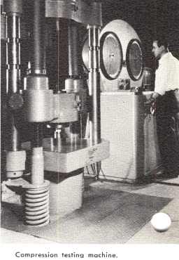
The compressive strengths of many materials have been measured in the Laboratory by cutting samples into one-inch cubes which are then broken under slow compression in a Southwark compression tester. This indicates the compressive strength in pounds per square inch.
The correlation between the compressive strength and the impact crushing strength is inconsistent, and experience has shown that the impact strength is a better criterion of the actual resistance to crushing. The impact device more nearly approaches actual crusher operation, both in velocity of impact and in the fact that broken stone is used in testing.
The average impact crushing strength is an indication of the energy required for crushing, while the maximum compression values indicate the danger of crusher breakage and the type of construction necessary. Crusher capacities do not vary greatly with the impact strength. There is a capacity increase of less than 10% from the hardest to the softest stone, where packing is not a factor.
The average impact strength of all materials tested is 15.3 foot-pounds per inch. The average of the maximum values of each material is 23.1, which is 151% of the average value.

