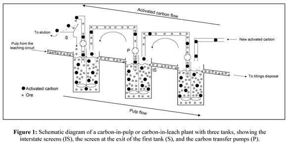
Cyanide is a lixiviant, or reagent that is used to leach, often in tanks, gold from a solid matrix and form a gold cyanide complex. The gold cyanide complex is then extracted from the pulp or slurry by adsorption onto activated carbon. CIL stands for carbon-in-leach. This is a gold extraction process called cyanidation where carbon is added to the leach tanks (or reaction vessel) so that leaching and adsorption take place in the same tanks. CIL is slightly different from another gold extraction process called CIP or carbon-in-pulp process. In the latter case leaching takes place in tanks dedicated for leaching followed by adsorption onto carbon in tanks dedicated for adsorption.

Leaching can be assimilated to the principle of preparation of tea. When we add tea in hot water, the aroma of tea will dissolve in the water and not the tea leaves. So the aromas is found in liquid form and tea leaves remains in solid form in the hot water. Thus we can separate (solid-liquid separation) tea aromas from tea leaves (filtration for example). At this stage , we have been able to extract aromas of tea from the tea leaves by changing the physical shape of the tea aromas.It is the same principle used in the leaching of gold. The gold that is in solid form in the ores turned into liquid form with cyanide in the presence of oxygen. That’s the way gold is separated from the majority of its gangue. The second step is the adsorption of gold on the surface of the activated carbon. Following a natural phenomenon known around the world (positive charges attract negative charges) Gold sticking to coal. the coal loaded with gold and some impurities is then transferred to the elution where he undergoes a cold wash which removes certain impurities and then a hot wash. The solution from the hot wash is transferred to the electrolysis where pure gold is recovered.
Learn Cyanidation
Carbon in Leach vs Carbon in Pulp:
Carbon-in-pulp (CIP) is the sequential leach then absorption of gold from ore. During the CIP stage, pulp flows through several agitated tanks where sodium cyanide and oxygen have been added to dissolve gold into solution. In the absorption stage, this solution flows through several agitated tanks containing activated carbon. Gold absorbs onto the activated carbon, which flows countercurrent to the pulp, while screens separate the barren pulp from the gold-loaded carbon.
Carbon-in leach (CIL) is a simultaneous leach and absorption process. The simultaneous leach and absorption phases of the CIL process were developed for processing gold ores that contain preg-robbing materials such as natural absorptive carbon. These reduce the gold yield by attracting gold meant for the activated carbon. Simultaneous leaching and absorption help minimize the problem.
CIP-CIL versus Agitated Tank Leaching
Process Description. The first industrial CIP plant was installed in South Dakota. A CIP circuit utilizes the same flowsheet as an agitated leach circuit up to the point where the slurry discharges from the final agitated leach tank. At this point, the precious metal values arc recovered directly from the slurry onto granulated activated carbon in agitated CIP tanks The carbon is retained in the tanks by any one of several different types of screens through which the slurry discharges CIP circuits are typically designed with at least four tanks to prevent short-circuiting of sluny and allow sufficient retention time for recovery of all the metals. Although agitated leach tanks are used before CIP tanks, CIP and CIL circuits are considered as a separate process.
CIL circuits are similar to CIP circuits with the exception that leaching and extraction occur simultaneously in agitated leach tanks that also contain carbon and are equipped with carbon retention screens
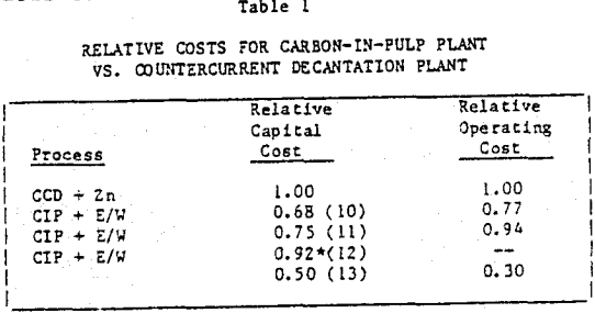
The evaluation of agitated tank leaching verses CIP and CIL circuits is not as complex as the heap leach-agitated tank leach analysis. CIP and CIL circuits generally have lower capital and operating costs for gold ore bodies than agitated tank leach circuits. Silver ore bodies show better economics with agitated tank leach-Merrill Crowe circuits. This is because the volume of carbon that would have to be processed to recover economic levels of silver would increase the capital and operating cost of a CIP or CIL circuit above that of an agitated tank leaching/CCD/Merrill-Crowe circuit.
Counter-current leaching. leaching efficiency can be enhanced by the application of Le Chatelier’s principle. In summary, the lower the concentration of gold in solution, the greater the driving force for gold dissolution to occur, although in a mass transport controlled reaction it is debatable what role this plays in gold leaching. An alternative explanation for this phenomenon is the reversible adsorption of Au(I) cyanide onto ore constituents. The gold adsorption is reversed when the solution is exchanged for a lower-grade solution or when a material (such as activated carbon or suitable ion exchange resin) is introduced into the slurry, which actively competes for the Au(I) cyanide species. This effect can be exploited in practice by performing intermediate solid-liquid separation steps during leaching to remove high-grade gold solutions, and re-diluting the solids in the remaining slurry with lower-grade leach solution and/or with freshwater plus reagents. Successful applications of this principle have been used at the Pinson and Chimney Creek, Nevada (United States), and East Driefontein (South Africa) plants, and at other operations.
https://www.911metallurgist.com/gold-leaching-process-and-methods
At many operating gold plants, an increase in gold dissolution is observed when a leach slurry is transferred from one type of process equipment to another (i.e., between leach tanks, thickeners, filters, pumps, and pipelines). This is explained by the different mixing mechanisms in the different equipment, coupled with other factors, such as changes in slurry percent solids, changes in solution composition, and the effects of pumping transfer (i.e., plug flow mixing).
Likewise, the benefits of the carbon-in-leach (CIL) process compared with leaching and carbon-in-pulp (CIP) have been clearly demonstrated both experimentally and in practice, even without the presence of interfering preg-robbing constituents in the ore. The CIL process results in improved conditions for gold dissolution as a result of the lower gold tenor, albeit at a cost of lower gold-on-carbon loading.
Developments in the Carbon-In-Pulp Process
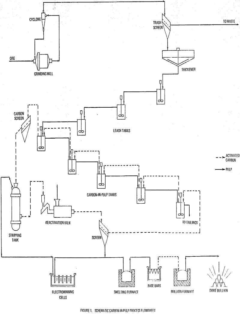
The process technology and equipment design are described in detail for the carbon-in-pulp process. A typical process flowsheet is given with a description of appropriate design criteria. Technical advantages and disadvantages as compared to the traditional countercurrent decantation process are discussed including some illustrative comparisons of capital and operating costs.
Design Criteria
In the carbon-in-pulp process activated carbon is mixed with a ground ore plus water slurry in which gold and silver cyanides are dissolved. After the precious metals are adsorbed onto the carbon, the loaded carbon is separated from the pulp and stripped. The barren pulp is disposed of as tailings and the precious metals are recovered from the strip solution by electrowinning or zinc precipitation.
The carbon-in-pulp process is used to treat low grade gold and/or silver ores. The ore is first ground in a ball mill which operates in closed circuit with a cyclone or similar sizing device. This is done to produce a feed suitably sized so that subsequent leaching is rapid.
The ground ore overflowing the sizing device generally runs at 25 to 35 percent solids. First it is passed through a trash screen to remove tramp oversize, plastics, wood, and other debris. It is then thickened to a requisite 40-50 percent solids prior to leaching. This range of pulp density keeps the activated carbon suspended in the pulp and is suitable for the subsequent leaching operation.
Following leaching, the pulp flows into the carbon-in-pulp circuit which operates in counter-current fashion. Usually five stages of adsorption are employed. Traditionally, 6 by 16 mesh activated carbon is added to the number 5 carbon-in-pulp tank and advanced to the number 4 tank and so on by air lift. The pulp is advanced from the number 1 tank to number 1 tank and so on by a second series of air lifts.
One of the most important factors in the carbon-in-pulp process is the minimization of gold losses on fine carbon reporting to the tailings. To date, the most abrasion resistant plus surface-active carbon has been found to be coconut shell carbon. Normally, the carbon consumption will average between 0.1-0.02 kg carbon per tonne of ore feed.
The loaded carbon containing adsorbed gold and silver plus base metal cyanides is screened and conveyed from the carbon-in-pulp circuit to the stripping circuit.
The traditional process for gold recovery from cyanide leach liquors has been the countercurrent decantation process. Following leaching, countercurrent decantation takes place in a series of thickeners in which the leach pulp is washed by the countercurrent flow of barren solution. The classified pregnant solution is treated for gold recovery with zinc dust. The precipitate may be acid digested. It is then smelted into bullion bars. The barren solution from zinc precipitation is returned to the last thickener.

Commercial Operations
The most well known carbon-in-pulp plant remains the prototype Homestake plant in Lead, South Dakota. Operating since 1973, this facility treats 2130 tonnes of ore per day averaging 2.7 g gold per tonne. Homestake has also operated small silver carbon-in-pulp plants at Creede and Cripple Creek, Colorado since 1979.
Duval Corporation operates a 2720 tonne per day carbon-in-pulp plant at Battle Mountain, Nevada with an average grade of 2.7 g gold and 3.4 g silver per tonne.


