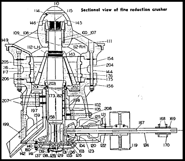
I covered briefly the development of various types of reduction crushers of the gyratory family. Below you see a gyratory reduction crusher, which introduced the cylindrical top shell, flared head, and reversible concaves. Even with the older style of straight concaves, with which this machine was originally fitted, it represented a distinct step forward in secondary crusher design, and the later introduction of non-choking concaves increased its efficiency and permitted the use of finer settings than were originally allowable. This type of machine, although it has been superseded in the fine reduction field by more efficient types, still rates as a very excellent crusher for secondary crushing work. It has good capacity at moderate settings, is ruggedly constructed, and has, for comparable sizes, relatively large receiving openings, as compared to machines designed primarily for fine reduction work.
To show why this machine was a distinct step forward in secondary crusher design, it is interesting to compare the action of its crushing chamber to the standard crusher chambers already described. To make clear the fact that the machine had certain advanced features, even before non-choking 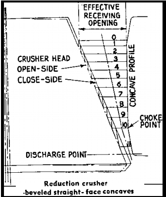 concaves were developed, lets first show a diagram of its crushing chamber with the older type of beveled, straight-face concaves. It should be mentioned that these beveled concaves were not the very earliest type used in this crusher; they were preceded by plain, straight concaves, which utilized the full rated receiving opening of the crusher, but had the same disadvantage we noted in connection with this type, as used in the standard gyratory concentration of wear at the discharge point.
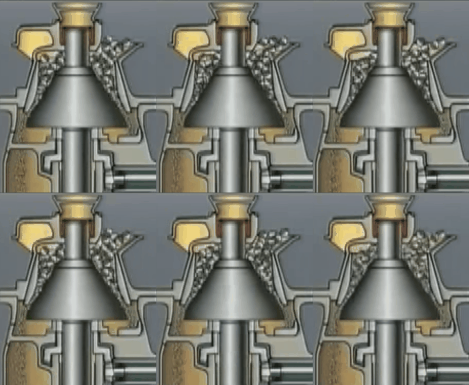 The beveled type spread the wear out somewhat, although at the cost of some reduction in the effective receiving opening.
The distinctive feature of the design shown here is the decided slope of the line-of-mean-diameters away from the center-line of the crusher, as this line runs down through the crushing chamber. As the volumes of the successive rings of material are functions of their diameters, as well as their areas, it is apparent that these progressively increasing diameters tend to offset the decreasing areas; in other words, the flared head spreads the material as it moves downward, thereby tending to minimize the ratio-of-volume-reduction. The actual compression-ratio in this chamber is about 1.5:1, which is lower than in either of the diagrams previously discussed and very much lower than the case of the standard crusher with straight concaves.
This became the cone crusher and this departure from the older conventional design was a decided improvement for secondary crushing is apparent when we compare two machines of approximately equal head diameters, a logical comparison because the diameter of the bottom of the crushing head directly affects the area of discharge opening and, hence, the capacity of the crusher. This 10″ reduction crusher, with its 40″ head, compares closely, in this respect, with the 20″ standard crusher, which has a 38″ head. Using straight-face concaves, the permissible minimum open side settings are 1.5″ for the former, and 3.5″ for the latter. With non-choking concaves these settings are, respectively, 1 1/8″ and 2 1/4″.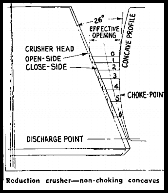
Non-Choking Concaves
To show the characteristics of this type of crusher when fitted with non-choking concaves we have prepared a diagram of the same size machine so equipped. You now have the cumulative benefits of the flared head and curved-profile liners. There is a marked reduction in the number of strokes required to shift plane “O” down to the discharge level; the choke-point has been raised, and the ratio of volume reduction is lower (about 1.2:1).
There is a decrease in the effective receiving opening, as compared with the straight-face chamber, when using “full-curve,” non-choking concaves, which is the type shown in our diagram. This effective opening is established by the maximum angle of nip; therefore it varies somewhat for different materials, and in different sizes of crusher. For this crusher 26 deg. was chosen as the governing angle; about 28 deg. is the conservative maximum for the largest machines of this type.
High-Speed Crushers
So far, all of the crushers we have been discussing have been of the “low-speed”class; that is, with eccentric speeds ranging between the approximate limits of 100-200 RPM. It is customary, as before mentioned, to rate such crushers at their open-side discharge settings, because there is a definite relationship between these values. Most modern crushers, designed for what may properly be classed as fine-reduction crushing, are of the high-speed type. The eccentric speeds and shape of the crushing chamber in the machines of this type are such that the maximum one-way dimension of the product particles is established by the close-side discharge setting; consequently it has become customary to rate these crushers at this setting.
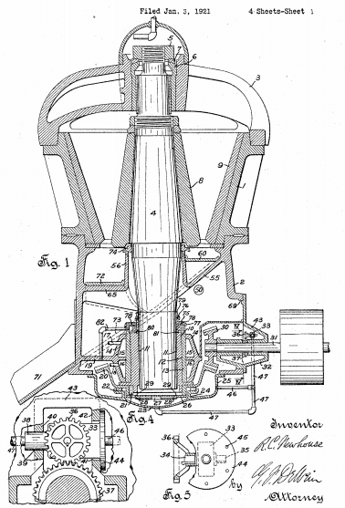 The Newhouse crusher was one of the early developments in the highspeed class of fine-reduction crusher incorporates several unusual features, at least one of which is unique in crusher design. The eccentric is direct-driven by a vertical motor mounted above the spider, the drive shaft running down through the hollow-bored mainshaft. Speeds range from 480 to 580 RPM, depending upon the size of the crusher, and upon the frequency of the electric current. Eccentric throws, as compared with those of the crushers we have been dealing with, are relatively low. This combination of small throw and high speed results in a very uniform product with a minimum amount of fines for any setting and ratio of reduction. A unique feature is suspension by means of cables, eliminating the usual foundation, although the crusher can be set on a foundation where required.
This crusher is usually furnished with full-curve, non-choking concaves, which are reversible in the top shell. These concaves are of the same general contour as those shown in the above diagram of the reduction crusher chamber and in general the crushing chamber is similar, except that the chamber in the Newhouse crusher is somewhat deeper and, consequently, the head does not have as pronounced a flare. The important difference in the crushing action of these two machines lies in the difference in eccentric speed. That of the Newhouse crusher is so high that no material can drop through the almost parallel zone just above the discharge point without being caught between head and concaves and broken to a maximum oneway size closely approximating the close-side setting.
This crusher can be set somewhat closer than comparable sizes of the reduction crusher previously described. Although it cannot be classed as a fine-crusher it does belong to the fine-reduction class. Furthermore, by virtue of its large receiving openings, it rates as a machine for secondary reduction work. When so used it is usually fitted with concaves of the non-reversible, non-choking type, which are designed to make use of the full rated receiving opening of the crusher, although they sacrifice the feature of reversibility which permits wearing both ends of the concaves.
