Conditioning
In small plants, it is common practice to include conditioners following the last stage of grinding. Additional conditioners are normally required between flotation operations which produce individual mineral concentrates. Each conditioner stage should consist of a minimum of two separate agitated tanks. Provision must be made to drain and clean conditioner tanks to appropriate flowsheet locations. This is particularly important in the case of conditioners which follow the grinding circuit since these tanks tend to accumulate oversize material produced during grinding circuit upsets.
Conditioners provide positions in the plant flowsheet wherein changes to the ore slurry are brought about by the addition of reagents and pH modifiers. Conditioners must always be designed to provide adequate time for chemical or physical changes induced by reagent additions to proceed to completion. Conditioners also serve a useful function in that swings in ore grade, particle size distribution, or other flotation variable tend to be partially homogenized and dampened during the conditioning unit operation. For example, in small installations it is not unusual to experience wide swings in feed grade. The conditioning unit operation provides the operator an opportunity to modify reagent additions in order to maximize recovery during periods of process instability. If possible, conditioner tanks should be arranged in tiers so that slurry overflows between sequential tanks under the influence of gravity.
Flotation
The selection of flotation cell size and configuration can have a substantial influence upon installed cost and can contribute to operational efficiency. Two possible flotation configurations for a 500 metric ton per day installation are presented in Figure 5. The computational basis assumes 30 percent solids in rougher flotation, 20 percent solids in cleaner, recleaner and cleaner-scavenger flotation, a ratio of concentration in rougher flotation of 3.07 an overall ratio of concentration of 5.0, and an ore specific gravity of 2.9. This representation indicates that the flotation bay layout employing the larger flotation cells, in this case 2.83 cubic meter (100 cubic feet) machines, occupies less area and reduces installed capital cost by about 25 percent. However, there are instances when the first illustration (selection of small flotation cells) would be chosen for reasons of compactness and symmetry.
Complex multiple product flotation installations usually require a high degree of sophistication regarding operational control. Many times, in small flotation concentrators this level of sophistication is not available. If the facility is located in a remote area, experienced operational personnel may be impossible to acquire. Consequently, the flotation circuits should be as simple as possible. For an installation producing a single mineral product, the flotation scheme illustrated in Figure 6 is recommended. This system, which is compatible with configuration 2 on Figure 5, is simple to operate and eliminates the build-up of a large circulating load of scavenger concentrate. This system is also flexible in that various produced concentrates can be subjected to regrinding should changes in mineralogy or primary grind so dictate.
It must be recalled that the weight of rougher and cleaner concentrates produced from high-grade ores can be substantial. Provision to remove froth by the use of froth paddles on all flotation cells should be included in the original design. The additional capital cost required for froth paddles is a reasonable investment since these devices tend to negate errors in flotation pulp level or frother addition. The open circuit flotation system presented can be operated by individuals having minimal training. The advice of Taggart regarding the inclusion of a small “pilot table” as a visual sample on rougher tailings is still legitimate.
In almost all new flotation installations, the use of launders fabricated from sheet rubber is recommended. Care must be taken to insure that all launders are sloped properly. In addition, launders must be provided with appropriate sprays and sluice lines to facilitate concentrate transport. The launder water system must be carefully designed to insure functionality without excessive concentrate dilution.
In recent years it has become popular to use vertical pumps for both concentrate and tailing transport in smaller circuits. It is usually possible to employ only one, or at the most two, pump sizes for all of the required flotation pumping installations. The same size vertical pump may also be used in various locations about the plant for cleanup duty. The usage of vertical pumps reduces seal water requirements, and eliminates concrete pump bases, fabricated sumps, and the valving associated with horizontal pumps.


FLOTATION MACHINES
For the past 35 years “Sub-A” Flotation Machines have been serving faithfully in all parts of the world. Anniversaries of progress such as this make reminiscing very interesting and we thought you would enjoy seeing some of the “Firsts” in the flotation machine industry as pioneered by the “Sub-A”.
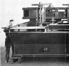
1928 was a pioneer in the use of V-belt drives in the flotation industry. This high-head machine also had wide-spaced greaseless lower bearings. At one time this was the largest flotation machine in the world.
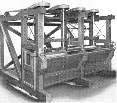
1927 One of the first “Sub-A” Flotation Machines ever built. It was a high-head wooden frame and tank with a quarter-turn flat belt and line-shaft drive.
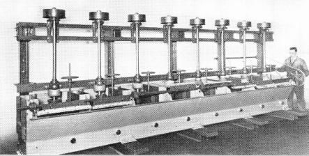
1930 First steel tank flotation machine. Earlier machines had wood tanks. Steel tanks met great opposition at first, later became standard. This high-head, all-steel “Sub-A” marked the introduction of anti-friction lower bearings.
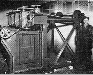
1932 First low-head flotation machine marked a radical departure from the then accepted principle that the space between bearings must be greater than the distance beyond the lower bearing. This machine was of the cell-to-cell pulp flow design and used a quarter-turn flat belt line-shaft drive.
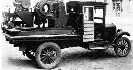
1934 A portable gold placer machine designed to recover fine gold by flotation. Many similar mills were sold for gold recovery during the great depression.
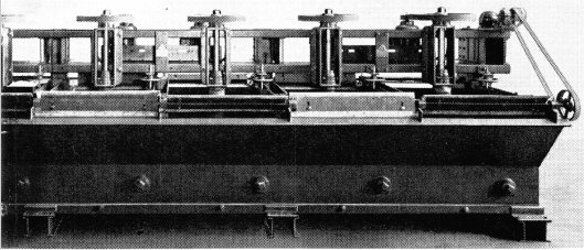
1933 First steel tank low-head, low-level flotation machine. It had an individual motor and a V-belt drive. This design became very popular with mill operators and thousands of cells were sold similar to those pictured above.
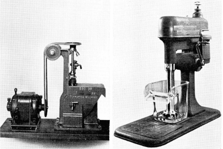
Laboratory Flotation Machines have made progress, too. In our early days the cast-iron tank machine with its round-belt “mule” drive was the latest word. Contrast it with today’s modern “Sub-A” Laboratory Flotation Machine with its heavy glass tank and stainless steel parts.
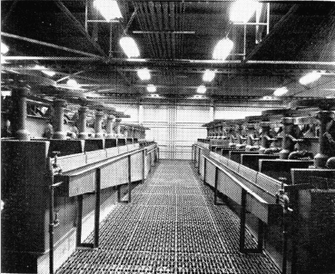
1952 Modern, high-tonnage mills use the open-flow “Sub-A” Rougher Flotation Machines with suspended mechanisms.
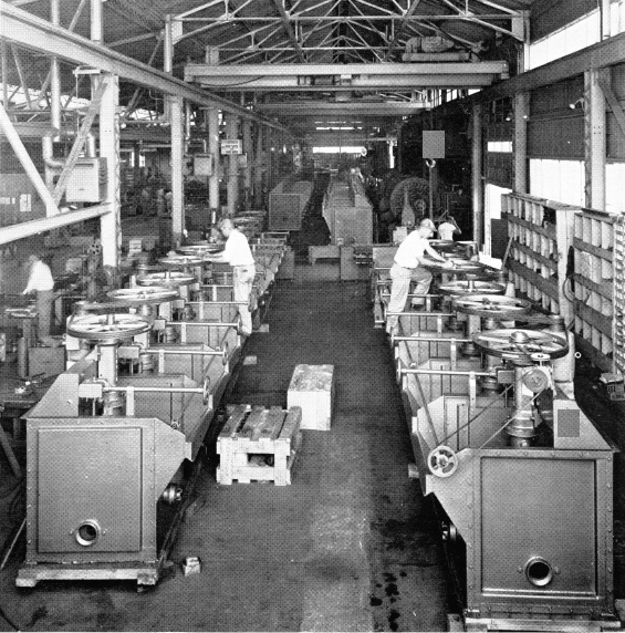
1961 Today’s demands for “Sub- A” Flotation Machines keep our modern factory busy. Today more “Sub-A” Flotation Machines are specified than all competitive makes and is the unquestioned “First Choice” in Flotation.