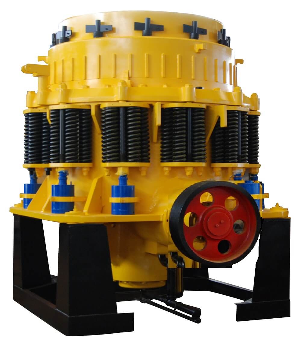
CONE CRUSHER MODELS & TECHNICAL SPECIFICATIONS


There is no startling revelation to the fact that the mining industry as a whole is generally moving toward the use of larger equipment to process ores in quantities far greater than what was even considered a decade ago. Trucks and shovels have led the way in extra large machines and many other manufacturers have followed suit in the development of so-called “supers” in their line of equipment.
In order to keep pace with the industry, crusher manufacturers have also enlarged the size of their equipment. There is now on the market, a Gyratory crusher capable of accepting a 72″ diameter piece of ore. Primary jaw crushers have also increased in size. It is inevitable, therefore, that larger secondary cone crushers would also be required to complement the other equipment used to process these large quantities of ore. This super-size secondary cone crusher is the SYMONS 10 Ft. Cone Crusher.
Until 1973, the largest cone crusher built was the 7 Ft. Extra Heavy Duty crusher, which is currently used in the majority of the mining operations throughout the world. The 10 Ft. crusher, when compared to the 7 Ft. Extra Heavy Duty Crusher, is approximately 1½ times larger in physical dimensions; three times heavier; will accept a maximum feed size which is approximately twice as large; and will crush at approximately 2¼ times the rate of the 7 Ft. machine at identical closed side settings. It will be the largest cone crusher built in the world.
The preliminary design studies for the 10 Ft. cone crusher were made in the early 1950’s. At that time, engineering investigations were made to determine the following:
- The general, physical shape of the machine;
- The capability of our shop to machine and assemble this size crusher;
- The theoretical capacity of the machine in tons per hour at various closed side settings; and
- An approximate cost to manufacture the machine.
The conclusions of this investigation were all positive – the crusher could be built and at a cost that would be in line with its size and capacity and also with other size crushers. After that preliminary study, the project became dormant for several years.
The project was reactivated and this time general assembly drawings were made which incorporated many improvements in the crusher such as pneumatic cylinders in place of the conventional, springs for tramp iron release, a two-piece main frame a dynamically balanced design of the internal moving parts of the crusher, and an automatic clearing and adjusting mechanism for the crusher. At this stage of development we felt we were ready to build a 10 Ft. crusher for any mine that was willing to try one. Unfortunately, the conservative posture of the mining industry did not exactly coincide with our sales plans. This, added to the popularity of the autogenous mill concept at the time, led to another lull in the 10 Ft. development program.
The project was reactivated again in 1970, this time primarily at the request of one of the large Minnesota Iron Range mining companies. We then undertook a comprehensive market research study to determine if there was a need for this size crusher by the mining industry in general, rather than just the iron ore industry. We talked not only to the iron ore people but to the copper people and persons connected with the other metallic ores as well. The acceptability of this large crusher was also discussed with the aggregate industry. After interviews with many of the major mining companies, the decision was made to complete the entire engineering phase of the development program and to actively solicit a customer for this new crusher. We spent approximately $85,000 on engineering work and tests on the gamble that we could find a customer. I speak of a gamble because during our market research study we continually were told “my company would be very interested in buying a 10 Ft. crusher, but only after we have seen one in operation”.
The actual building and test of the first prototype unit without a firm commitment for a sale was an economic impossibility. We were now at the point where we needed to sell at least one unit in order to prove not only the mechanical reliability of the machine, but the economic justification for its purchase as well. Needless to say, when the order for two SYMONS 10 Ft. cone crushers was received, we felt we were now on the way toward completion of the development program.
A SYMONS CONE CRUSHER
Perhaps at this point it might be apropos to examine the crusher itself. It will stand 15′-6” above its foundation, the overall height will be 19′-4-¼”. At its greatest diameter, in the area of the adjustment ring, it will be approximately 17′-6″. It will weigh approximately 550,000 lbs. Under normal crushing conditions, the crusher will be connected to a 700 HP motor. A 50 ton. overhead crane is required to perform routine maintenance on this crusher.
The main shaft assembly will weigh approximately 92,000 lbs. and the bowl assembly approximately 95,000 lbs. The mantle and bowl liner, cast from manganese steel, will weigh approximately 13,000 lbs. and 25,000 lbs. respectively.
The throughput capacity of the Standard will be approximately 1300 TPH at a 1″ closed side setting and 3000 TPH at a 2-½” closed side setting. The throughput capacity of the SHORT HEAD will be approximately 800 TPH at ¼” closed side setting and 1450 TPH at a 9/16″ closed side setting.
Persons familiar with the design of a conventional 7 Ft. SYMONS cone crusher will recognize that the design of the 10 Ft. is quite similar to it. As a matter of fact, we like to say that the design of the 10 Ft. is evolutionary rather than revolutionary, because all the reliable features of the SYMONS cone crusher were retained and the only changes that were made were those that added to the convenience of the operator, such as automatic clearing and automatic adjustment. From a mechanical point of view the stresses generated due to crushing loads are less in the 10 Ft. crusher than in the existing 7 Ft. Extra Heavy Duty cone.
HYDROCONE CONE CRUSHER
A multi-cylinder Hydraulic Cone Crusher, the Hydrocone Cone Crusher can be used in either the second or third stage of crushing by merely changing liners and adaptors.  It can produce the full product range that the combination of a comparable sized Standard and Short Head can produce. It makes the machine much more versatile. It allows for much more standardization. The value of this feature is one where spare parts investment in the form of major assemblies is minimized.
The Hydrocone Cone Crusher uses hydraulic clamping cylinders to hold the bowl securely in the threads. These cylinders are located in pockets between a clamp ring and the adjustment ring.

Hydrocone Cone Crusher Crushers are equipped with a fingertip hydraulic control that adjusts the crusher setting for optimum performance, while the crusher is operating under load.
All operator controls are conveniently mounted on a remote control console to eliminate the need for an operator to approach the crusher during operation. Over a period of years we have developed a unique engineering knowledge about the effects of cone crusher design parameters such as speed, throw and cavity design on crusher productivity.
Hydraulic Tramp Release
Each Hydrocone Cone Crusher features dual function hydraulic cylinders that provide overload protection and a safe and fast way to clear a jammed cavity. Should the crusher become plugged, the operator merely pushes levers on the remote control console to clear the cavity.

HYDROCONE CONE CRUSHER
A multi-cylinder Hydraulic Cone Crusher, the Hydrocone Cone Crusher can be used in either the second or third stage of crushing by merely changing liners and adaptors.
It can produce the full product range that the combination of a comparable sized Standard and Short Head can produce. It makes the machine much more versatile. It allows for much more standardization. The value of this feature is one where spare parts investment in the form of major assemblies is minimized.
The Hydrocone Cone Crusher uses hydraulic clamping cylinders to hold the bowl securely in the threads. These cylinders are located in pockets between a clamp ring and the adjustment ring.
Hydrocone Cone Crusher Crushers are equipped with a fingertip hydraulic control that adjusts the crusher setting for optimum performance, while the crusher is operating under load.
All operator controls are conveniently mounted on a remote control console to eliminate the need for an operator to approach the crusher during operation. Over a period of years we have developed a unique engineering knowledge about the effects of cone crusher design parameters such as speed, throw and cavity design on crusher productivity.
Hydraulic Tramp Release
Each Hydrocone Cone Crusher features dual function hydraulic cylinders that provide overload protection and a safe and fast way to clear a jammed cavity. Should the crusher become plugged, the operator merely pushes levers on the remote control console to clear the cavity.

MONO CYLINDER HYDRAULIC CONE CRUSHER
The Hydraulic Cone Crusher uses hydraulic tramp release cylinders and accumulators to hold the adjustment ring against the main frame seat. There is only one angular surface between the main frame and the adjustment ring which also has a radial contact point in the lowermost area. When a piece of tramp goes through the crusher, the oil is forced into the accumulators allowing the adjustment ring to raise and pass the tramp.
The tramp release cylinders coupled with the accumulators return the crusher to its original setting after the tramp has been passed.
The tramp release cylinders are secured to the adjustment ring and the lower portion of the main frame through clevises. This allows the crushing forces to be transferred directly from the frame arm locations to the adjustment ring. This relieves the main frame shell and upper flange from carrying heavy loads.
Main frame pins are also provided on the Hydraulic Cone Crusher to prevent the adjustment ring from rotating.
The Hydraulic Cone Crusher is equipped with hydraulic clearing. The tramp release cylinders which hold the adjustment ring in place are double acting cylinders. These cylinders can be pressurized in the opposite direction, after the clamping pressure has been released, to raise the adjustment ring and bowl assembly for clearing; only the weight of the adjustment ring, clamp ring, and bowl assembly, plus any residual material in the bowl hopper raises.
The distance through which the adjustment ring can be raised is more than adequate to clear a crusher which has been jammed.


