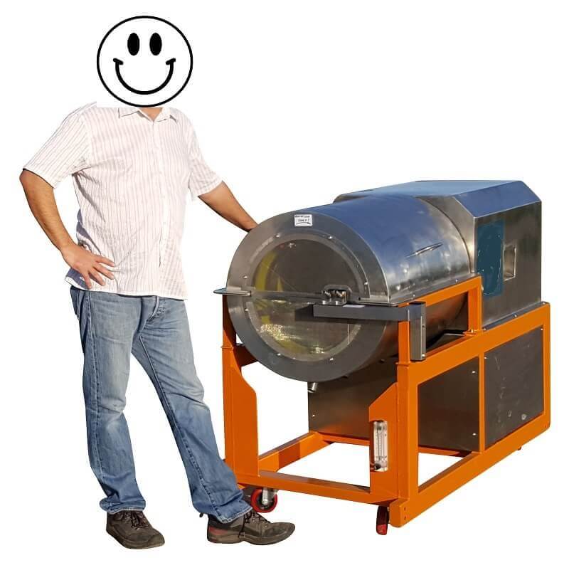
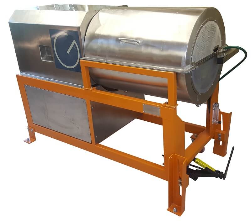
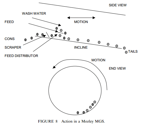
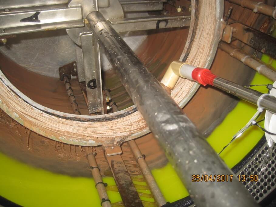
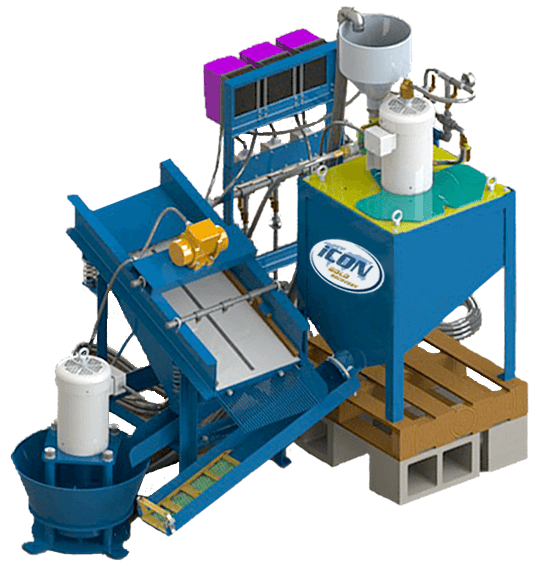
For full-scale production the 911MPEC902 Double Drum MGS is available. Extensive trials have demonstrated that this unit, measuring 4.7m x 1.5m x 1.8m high, will produce similar grade and recovery to the 911MPEC900 MGS while treating between 10 and 25 times the feed tonnage.
INITIAL SETTING UP OF THE MOZLEY DRUM
Lifting & Handling
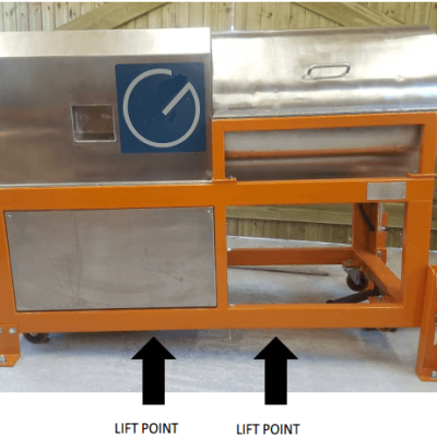
Use forklift truck or similar mechanical aid to lift equipment from the underside of the main frame at the indicated positions.
The MGS is fitted with castor wheels and can be easily moved on a flat surface.
Bolting Equipment to Floor
- Position the MGS on a level concrete floor.
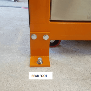
- Using two 19mm spanners slacken the bolt securing each rear foot in the raised position.
- Swing the feet into the position shown (this will take the weight of the castor wheels).
- Fit the second nut and bolt provided for each foot. Leave these nuts finger tight until tilt angle has been set.
- Use a 12mm masonry drill bit to make a hole in the floor corresponding with the holes provided in the feet.
- Use anchor bolts to secure the two rear feet to the floor as shown.
Feed Arrangement – Continuous Feeding
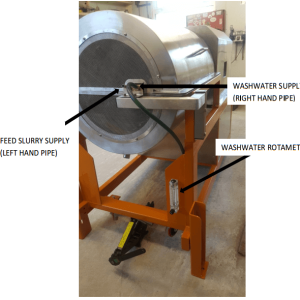
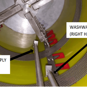
Where a continuous supply of feed slurry is available, or the feed is supplied via a pump from a stirred tank, connect a hose of suitable size (12.5mm ID), fitted with a control valve if necessary, from the feed supply to the left hand pipe on the feed/wash pipe unit.
Washwater
Before dispatch the rotameter is fitted with a plastic packing strip to prevent breakage of the glass tube by the metal float during transit.
- Remove front cover of rotameter
- Pull out clip retaining top plug
- Ease top plug out of glass tube
- Remove packaging material
- Reassemble rotameter
- Connect a 12.5mm hose from water supply to the lower rotameter inlet position
- Connect wash-water hose (the longer length of hose supplied) from the rotameter outlet to the right hand pipe on the feed/wash pipe unit)
Electricity Supply
Connection of electricity supply must be done by a competent electrician. Connect the electricity supply to the isolator fitted at the rear of the machine. Check motor rating plates to confirm correct electricity supply.
Important:
- Do not operate machine before carrying out checks described in section 5.
- Drum rotation must be clockwise when viewed from the open end.
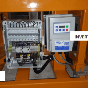
- The electrical enclosure and inverter are set during commissioning and do not contain ‘user’ adjustable controls.
INITIAL TEST RUNNING
Inspection
- Disconnect the electricity supply
- Remove the four locating screws from the launder/guard
- Carefully remove the launder/guard
- Carefully inspect the inside of the drum to ensure there are no loose objects or components that may interfere with the drum’s rotation or oscillation
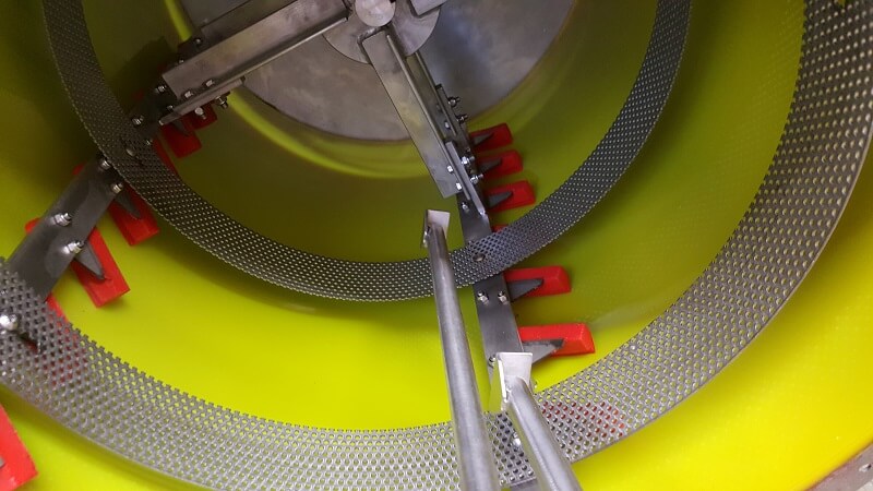
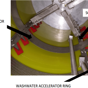
- Ensure the scrapers are fitted non-rigidly to the four scraper bars at an angle of 60° to the drum axis
- Rotate the drum by hand over several revolutions in a clockwise direction (NEVER anticlockwise) when viewed from the open guarded end. This ensures that the drum and scrapers rotate freely and that all scrapers are undamaged and in the correct position.
- Replace launder
- Replace the four locating screws to the launder/guard
- Remove the four locating screws from the rear cover
- Remove the rear cover
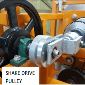
- Rotate the shake drive pulley by hand to ensure the drum and shaft assemblies oscillate freely.
- Replace rear cover
- Replace four locating screws to the rear cover
Electrical Controls
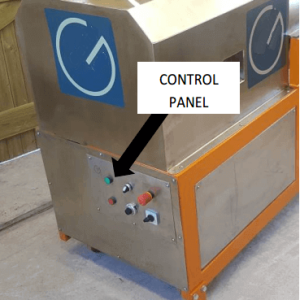
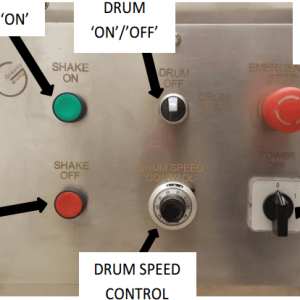
Electrical controls are mounted on a panel at the rear of the machine. The electrical enclosure and inverter are located within the body of the MGS and must not be adjusted by the user. The settings are adjusted during commissioning by a qualified person. For information the Lenze SMV frequency inverter manual is supplied as an addendum.
TEST RUNNING
Ensure Electricity Supply is Disconnected
- Remove the lower side panels,
- Remove tension from layshaft drive belt by slackening clamp bolt on layshaft drive motor mounting plate.
- Remove belt from motor pulley
- Reconnect electricity supply
- Switch isolator to ‘ON’ position
- Switch on rotary drive
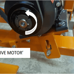
- Ensure the motor rotates in the direction indicated by the arrow
The Drum must Rotate Clockwise when Viewed from the Open Guarded End
If the Drum Rotation is not Correct Press Stop Button
- Isolate the machine from the electricity supply
- Arrange for a competent electrician to reverse polarity of connections at the isolator.
- Reconnect to the electricity supply
8. Refit belt to motor pulley
9. Set correct tension to layshaft drive belt
10. Tighten clamp bolt on layshaft drive motor mounting plate
11. Fit lower side panels
12. Check shake mechanism operates satisfactorily by pressing shake ‘ON’ button
13. Switch off using either stop button and switch or the isolator
Note: Multi Gravity Separator must not be used without Wash-water. this ensures lubrication of the scrapers.
MULTI GRAVITY SEPARATOR OPERATING VARIABLES
Tilt Adjustment
The machine is fitted with sliding feet which are adjusted as follows:
- Slacken the four bolts securing the two rear feet to the MGS using two 19mm spanners. These feet are already bolted to the floor.
- Slacken the four bolts securing the two front feet using two 19mm spanners
- Raise the front of the MGS to the required height using a jack or a lever at the jacking point indicated
- Slide the feet to the required position
- Re-tighten rear feet and sliding feet bolts
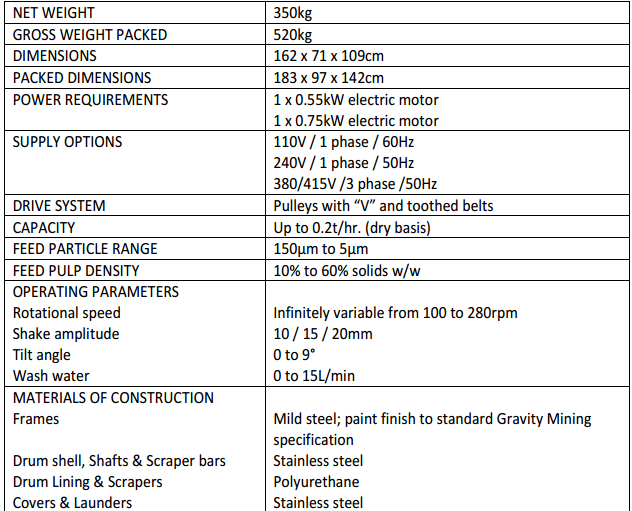
In practice a tilt angle of approximately 4° is usually found to be satisfactory for feed solids finer than 250µm
A combination of larger tilt angle with faster rotational speed will usually produce higher concentrate grades
ROTATIONAL SPEED OF AN MGS
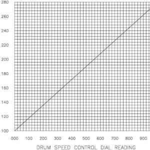
The rotational speed of the drum is controlled by a variable speed controller mounted below the layshaft, accessible on removal of the right hand panel. Speed is adjustable between 100 and 280 rpm using the rotary speed control (this is a ten turn potentiometer) mounted on the control panel.
As a factory setting the speed control is set to give (for a 240v 50Hz supply):
| RPM |
reading |
| 100 |
000 |
| 150 |
275 |
| 200 |
555 |
| 280 |
999 |
These figures are correct where the electrical supply is 240 volts 50Hz. Calibration will vary with voltage frequency. On installation check the drum speed over a range of settings and if necessary plot a revised calibration chart similar to the one below.
Shake Frequency of a Mozley Separator
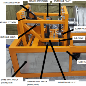
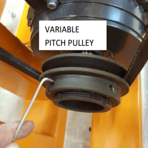
Adjust shake frequency by adjusting the variable pitch pulley using the 4 Allen screws.
How To Change Shake Frequency of the Drum
- Disconnect Electricity Supply
- Remove cover and lower side panels.
- Slacken the Allen screws on the variable pulley adjustable flange
- Screw the adjustable flange to reduce the distance between both flanges and therefore increase the ‘V’ belt tension and the shake speed
- Unscrew the adjustable flange to increase the distance between both flanges and therefore decrease the ‘V’ belt tension and the shake speed
- Use trial and error to adjust the shake speed
- When satisfied with the shake speed, tighten the Allen screws to lock the flange in position
- Replace covers
- Re-connect to electricity supply.
The variable range is 52 to 78 pitch diameters
In Practice it is Usually Unnecessary to Change the Shake Speed from the Factory Setting.
AMPLITUDE
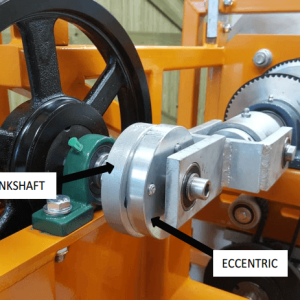
Use the variable eccentric to adjust the amplitude of shake.
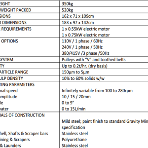
The options available are
HOW TO CHANGE THE AMPLITUDE THE THE MOZLEY DRUM
- Ensure Electricity Supply is Disconnected
- Remove cover
- Using 17mm spanner, slacken the three bolts securing the eccentric to the crankshaft
- Prevent crankshaft rotation by holding tightly.
- Rotate eccentric until the amplitude setting on the eccentric aligns with the mark on the crankshaft
- Tighten the three bolts securing the eccentric
The factory setting of amplitude is 15mm in practice a small amplitude is usually used with a higher shake speed and vice versa
Washwater
Washwater flowrate is adjustable between 0 to 10 L/min by means of the thumb valve below the rotameter.
The quantity of washwater required will normally depend on the density of the minerals treated. For lower SG minerals a flowrate of 2L/min may be sufficient whereas for high SG minerals a flowrate of ≥ 6L/min may be required.
Increased washwater gives a cleaner concentrate (dense fraction), but also results in increased loss of dense mineral to tailings. Solids of lower specific gravity (such as barytes) usually require less wash water than materials with higher specific gravity (such as cassiterite) or coarse solids.
Feed Rate
Depending on the nature and particle size of the feed solids, throughput may vary between 50 and 200kg/hr. of dry solids. For finer solids (<75µm) an acceptably clean concentrate with good recovery is usually produced with a throughput of 100kg/hr.
As a general guide use feed pulp density of 40% w/w with a flowrate of 2 L/min.
Important: do not exceed a feed rate of 200kg/hr. of solids.
Overloading may damage the drive belts
Feed pulp density & classification
Feed pulp density may be varied between 15% and 50% solids w/w. The higher pulp density feeds will require additional washwater. It is usual to use a pulp density of 30% solids w/w.
As with any gravity concentrator a deslimed or classified feed is always preferable. Undeslimed, low density feeds will require higher rotational speeds and vice versa.
Heavy Duty Scrapers
When treating high density minerals at high concentrations (for example magnetite concentrate) it is necessary to fit heavy duty scrapers. These are available upon request.
MULTI GRAVITY MOZLEY SEPARATOR DRUM TEST PROCEDURE
Simulated Continuous Testing
The MGS is a continuous processing separation machine and in order to achieve an accurate indication of its true performance it is preferable to use a test procedure which more closely simulates continuous operation. For this a minimum of 10kg of sample solids is required per test.
Proceed as follows:
- Carry out initial setting-up procedure- see Section 4
- Start with the following settings :
| Tilt |
4° |
| Rotational Speed |
200rpm (mid-range) |
| Shake Speed |
4.8cps (mid-range) |
| Amplitude |
15mm (mid-range) |
| Washwater |
3L/min |
3. Carry out initial test running procedure- Section 5
4. Isolate From Electricity Supply
5. Loosen and remove four set screws
6. Remove upper launder
7. Using a water hose, thoroughly wash out all compartments and drum, ensuring that no residue remains from previous test runs.
8. Replace launder
9. Re-connect to electricity supply.
10. Place a sample bucket under the tailings discharge pipe, another under the concentrate discharge pipe and a third under the centre spillage discharge pipe.
11. Mix a minimum of 10 kg of dry sample with water to give a pulp with a density of between 30 to 50% solids w/w (volume will be 28 and 14 litres respectively). To ensure adequate dispersion of the solids it is advisable to add a dispersing agent (i.e. Sodium Polymetaphosphate). Ensure all lumps or agglomerates are fully dispersed. The solids must be kept in homogeneous suspension for the duration of the test using a mechanical stirrer.
Stir the feed pulp vigorously to keep all particles in suspension.
12. Open the water valve below the rotameter and adjust to give a washwater flowrate of 3L/min.
13. Reconnect to electricity supply and switch on isolator.
14. Press shake starter button and switch on rotary drive to set the MGS in operation.
15. Set speed control to 555 (to give 200rpm). Leave the settings for shake speed and amplitude unaltered for the initial series of tests. Set tilt to approximately 4°. Optimise the results by varying the settings (by trial and error) in subsequent test series. Keep settings for shake, amplitude and tilt angle constant in a test series while varying rotational speed and washwater flowrate.
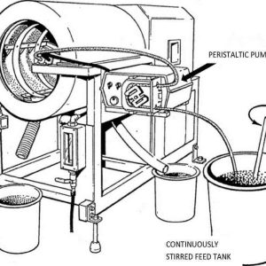
16. Using a suitable pump (a peristaltic type is recommended) introduce the feed pulp into the MGS at a steady feed rate of 1 to 2 L/min.
17. Allow the MGS to run under steady feeding conditions until operation becomes completely stabilised. This usually takes between 2 and 5 minutes, depending on the nature of the sample and the grade of the heavy mineral present. Check buckets frequently and replace when they become full.
18. When conditions have become stabilised use clean buckets to simultaneously collect timed samples of concentrate and tailing products. Allow sufficient time to collect a reasonable quantity of concentrate (this may have a very low flowrate). Between 10 and 30 seconds is normally adequate.
19. After collecting the test products turn off the feed and allow the MGS to operate until the bulk of the remaining solids have discharged, either to drain or into the original buckets.
20. Turn off the washwater and stop the MGS.
21. Isolate From Electricity Supply
22. Remove upper launder.
23. Using a water hose wash all remaining solids from the launders and drum (inside and out) either to drain or into the original buckets. Rotate drum by hand while washing out to ensure removal of all solids.
24. The two samples required for full evaluation of the test will consist of
| CONCENTRATE OR DENSE FRACTION |
Scraped or conveyed product collected over a timed period via front launder with the MGS running in a stabilised condition |
| TAILINGS |
Product containing low density solids collected over the identical timed period from the rear launder. |
Note: Any spillage collected from the centre spout should be combined with the concentrate sample.
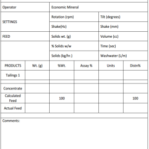
25. Dry, weigh and analyse the samples (see Section 8).
All Other Samples May Be Discarded.
Carry out several tests using different operating settings, to optimise performance.
It is not necessary to vary tilt, shake frequency or amplitude. As a guide, adjust rotational speed and/or washwater as follows:
| TOO MUCH CONCENTRATE PRODUCED |
Reduce speed and/or increase washwater |
| INSUFFICIENT OR NO CONCENTRATE PRODUCED |
Increase speed and/or reduce washwater |
Recommended Arrangement For Continuous Testing
INTERPRETING THE LABORATORY MULTI GRAVITY SEPARATOR DRUM TEST RESULTS
Procedure
Interpretation of test data will vary depending on the sample and will, of course, vary with the amount of information required.
Use the following procedure
- Remove excess water from the test products. This may be achieved either by filtering or by allowing all solids to settle, then decanting or siphoning off the clear water.
- Transfer the damp solids to enameled steel or stainless steel trays, using a small amount of water from a wash bottle to ensure that all solids are recovered from the buckets.
- Dry the samples in an oven at a temperature of approximately 100°C.
- Allow to cool.
- Weigh the dried samples carefully
- Assay for the element or mineral of interest.
- Calculate grade and recovery data in the conventional manner.
MAINTENANCE OF THE MOZLEY DRUM
Carry out regular maintenance as part of a planned maintenance system.
- Always check and if necessary adjust the drive belt tension. (Section 9.1)
- Inspect all bearings and seals. (Section 9.2)
- Lubricate all bearings (Section 9.3)
- Tighten all nuts & bolts
- Inspect drum and scrapers for signs of wear
Drive Belts
- Tension drive ‘V’ belts by slackening the motor mounting plate clamp bolts, pressing down on the motor and re-tightening the clamp bolts
- Tension timing belts by adjusting the positions of the three jockey pulleys
Belts used are as follows (also see 9.2)
| Rotational Drive ‘V’ belt |
SPZ 1060 |
| Shake Drive ‘V’ belt |
SPZ 1737 |
| Drum Drive Belt |
390 L100 |
| Scraper Drive Belt |
367 L100 |
Bearings, Seals & Drive Belts
Check all bearings, seals and drive belts at regular intervals and change if necessary. When ordering replacement parts pleas use stock code numbers shown on Page 35.
Lubrication
Apply grease at regular intervals to nipples on Pillow Blocks and swivel bearings using a snap-on grease gun.
Use a general purpose lithium based grease for all lubrication purposes.
Motor bearings and all other bearings are sealed units with sufficient lubricant for life.
TROUBLESHOOTING A MULTI GRAVITY SEPARATOR
Mgs Vibrates or is Unstable in Operation
- Check if rear feet bolts (to floor/frame) are loose. Tighten if necessary
- Check if front feet bolts are loose. Tighten if necessary.
- Check if a font foot is not in contact with the floor. Readjust if necessary.
Little or no Concentrate Produced
- Check if rotational speed is too low. Increase speed.
- Check if washwater flowrate is too high. Reduce flowrate.
- Check if tilt angle is too steep. Reduce angle.
- Check if shake intensity is too high. Reduce shake frequency and/or amplitude.
- Insufficient quantity of feed solids and short feeding time. If there is no conveyed product (concentrate) the material remaining on the drum inner surface at the end of the wash period may (as an approximation) be considered to be the concentrate. Under normal continuous running conditions only tailing and concentrate are produced.
- Loose or broken scrapers. Re-fit or re-new.
- Loose or broken drive belts. Tighten or re-new
Do Not Overfeed The Mgs Or The Driving Belts Will Break.
Little or no tailing produced (i.e. Too much concentrate)
- Rotational speed too high. Reduce speed.
- Washwater flowrate too low. Increase flowrate.
- Tilt angle too shallow. Increase angle.
- Shake intensity too low. Increase shake frequency and/or amplitude.
Shake Not Operating
- Loose or broken drive belt. Tighten or re-new.
- Check shake drive and transmission system.


