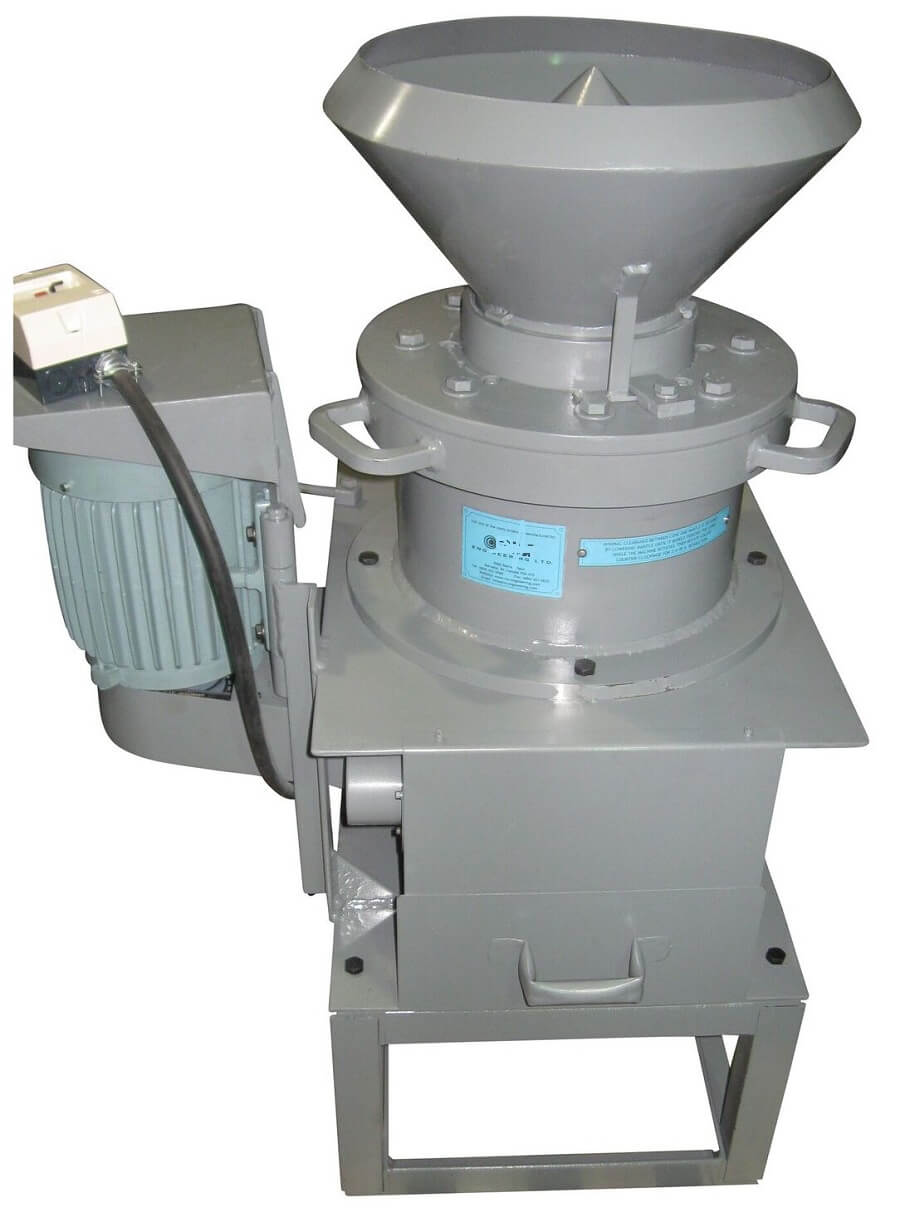
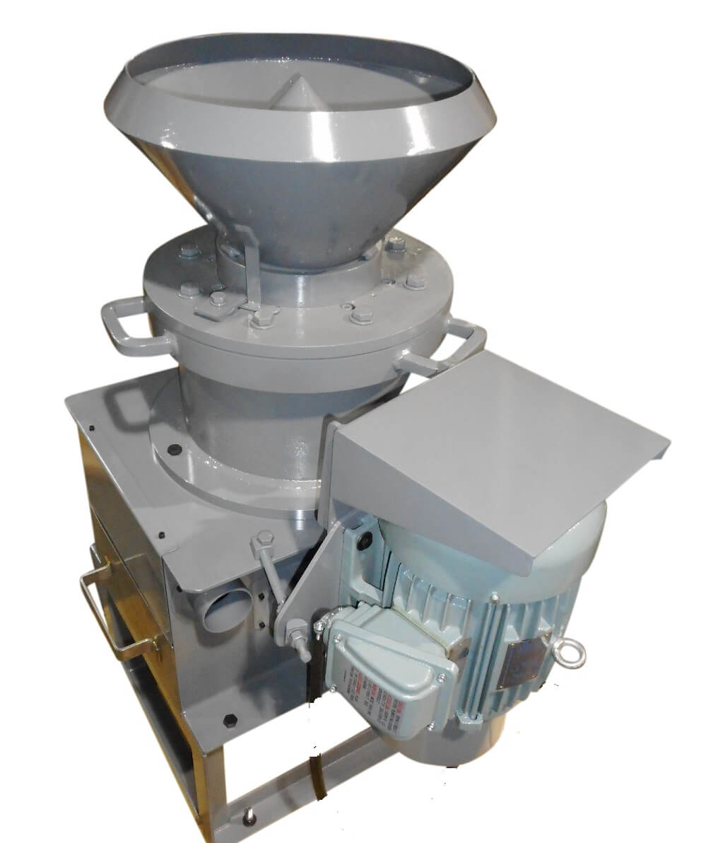
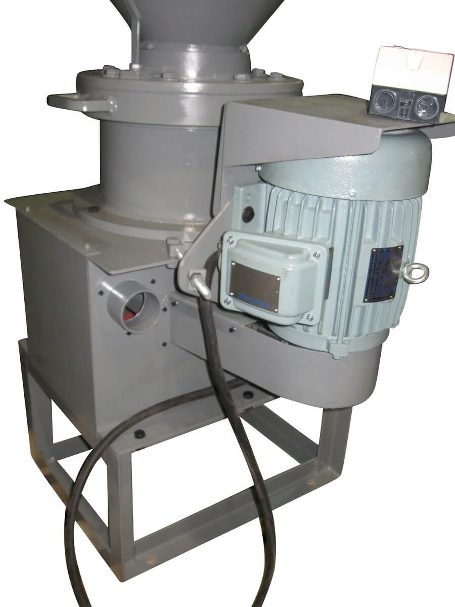
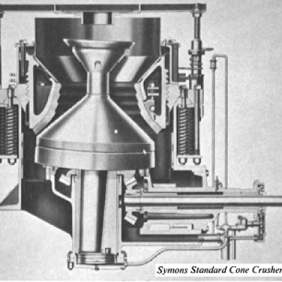
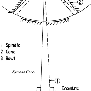
As with the gyratory, crushing results from interaction between three essential parts. The important difference is that in this case the spindle (1) is not hung from its upper end but is supported in a universal bearing below the gyrating head or “cone” (2). Normals to the arc through the universal bearing carrying the breaking head intersect at O. This breaking head gyrates inside an inverted truncated cone (3), called the bowl, which flares outward and thus allows for the “swell” of the broken ore by providing an increasing space for it to enter after each “nip” has released crushed ore for a further drop.
Industrially, two types are made, the standard and the short-head. These differ chiefly in the shape of the crushing cavities. Standard crushers deliver a crushed product varying from ¼” up to 2½” usually in open circuit and can be fitted with fine, medium, coarse, or extra-coarse crushing cavities. Short-head cone crusher has a steeper head angle, a longer parallel section between cone and bowl, and a narrower feed opening. They deliver a crushed product ranging from 1/8″ up to ¾”, and usually work in closed circuit.
The clearance between cone and bowl helps the ore to spread as it works its way down. Choked crushing is avoided since the rock gravitates into an increasing cross-sectional area. The “throw” of the gyrating cone is greater than would be practicable in primary crushers, which must withstand heavier working stresses. Higher speeds are also used (from 435 RPM up to 700 RPM), and particles appear to flow through the machine, partly because of their freedom of movement and partly because, at each revolution, the gyrating head drops from under the recently nipped material. Unlike that for primary crushers, the set is the minimum discharge opening, since during its last two or three nips, the particle of ore must pass through a parallel-sided crushing zone. Tramp oversize can escape, when un-crushed oversize particles succeed in forcing the bowl up, or if clayey feed accumulates on the crushing faces. In the former event the bowl, normally held down to its job by nests of springs, yields sufficiently to allow the object to pass through.
The springs then return the bowl to its correct clearance. While this happens or when choked with clay, the Symons cone crusher is apt to let oversize escape. Such clay is sometimes dealt with by introducing water with the feed. Better practice is to remove it by washing. It is dangerous with any dry-crushing machine to risk the entry of abrasives into its bearings or bevel gears.
The springs then return the bowl to its correct clearance. While this happens or when choked with clay, the Symons cone crusher is apt to let oversize escape. Such clay is sometimes dealt with by introducing water with the feed. Better practice is to remove it by washing. It is dangerous with any dry-crushing machine to risk the entry of abrasives into its bearings or bevel gears.
The springs which hold down the bowl yield when the load is too severe. It is therefore usual to run the cone crusher in closed circuit with a screen, thus ensuring that “tramp oversize” is returned for further treatment. This recirculated material, which may include fragments of non-magnetic steel not removed by the guard magnet, may call for removal by special methods.
With some ores there is a tendency for extra tough particles to “spring” the crusher at a slight oversize to the set. This leads to accumulation in the closed circuit of such particles, and if neglected can build up sufficient pressure in the crushing throat to present a problem not met with in the types of crusher. In passing, it should be noted that in all closed circuits there is selective retention of one fraction of the ore stream which may call for special measures. A simple solution is to use a screen slightly over-sized to the set of the cone crusher, and thus increase the severity of the crushing action upon the most prominent (largest) particles.
Ratio of reduction is controlled by screwing the bowl up or down by means of its capstan and chain. It is usually held between 3:1 and 7:1, though higher ratios can be worked with some ores.
A 2′ standard cone crusher receiving —2¾” rock is rated to deliver 15 tons/hour —¼” in open circuit, or 60 tons/hour when reducing —4″ feed to 1½”. A 2-ft. short-head crusher receiving 1 3/8″ feed and delivering 1/8″ in closed circuit has a capacity of 6 tons/hour. When reducing —2″ feed to —½” product the capacity is 20 tons/hour. The coarser 7-ft. standard crusher has a capacity of 900 tons/hour when reducing —18″ rock to 1½”. Such general figures, taken from manufacturer’s literature, would require checking for performance on samples of the specific ore if it was proposed to work a crushing plant at full capacity.
In the Hydrocone crusher the cone is held up to the correct setting by a hydraulic jack instead of by springs. An automatic method of reset allows the cone to yield when an uncrushable object enters, and to return to the correct setting after this has passed through.
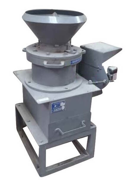
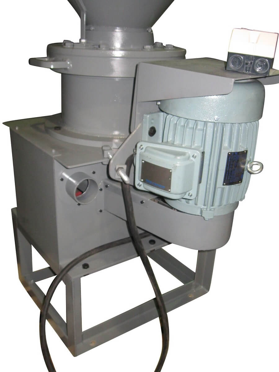
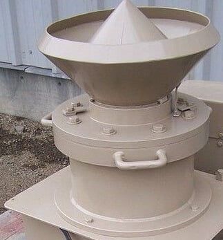
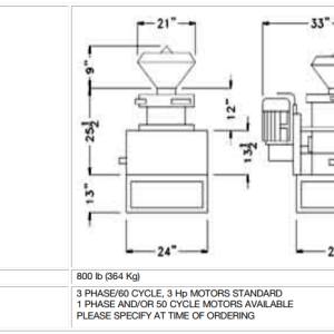
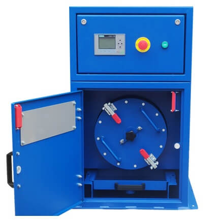
CONE CRUSHER USER MANUAL
Note: This machine is pre-lubricated at the time of assembly and needs neither further lubrication, servicing, nor maintenance. Disassembly should be done only when needed and by qualified people.
We decline all responsibilities if mishaps occur due to unqualified person wiring and manipulating the electrical and mechanical system of this machine.
INSTRUCTIONS FOR DISASSEMBLING HIGH REDUCTION CONE CRUSHER
- Blow entire machine with air to clean away all loose dust and particles. This will prevent precise parts, such as bearings, from becoming contaminated.
- Remove belt guard and belt drive pulley from cone mill shaft.
- Remove mantel locking bolts, washers, and turn the adjusting collar so that the top of the collar is flush with the top of the threads. Remove mantel by inserting ½” national coarse jack screws 4″ long in mantel flange holes. Turn jack screws simultaneously to raise mantel out of cone mill body. Note: there is no standard ½” N.C. bolts with 4″ threads. Use a ready threaded rod with double nuts tightened together as drive.
- Remove the 8 bolts holding the main cone mill body to the supporting frame and lift it out. Take care not to damage the protruding shaft.
- Since cone and shaft are mounted as a complete unit, they also have to be removed from the main cone mill body together. With the main cone mill body lying horizontally, remove the lower lock nut and lock washer. Then remove the cap screw on the top of the cone. This will release the protective steel cap. Remove it. Re-insert the cap screw and drive it in all the way. This will force out almost completely the compressed protective rubber ring inside the cone along with it’s steel holder. With vise grip pliers grabbing the screw cap, pull additionally to complete the operation.
- At this point, two persons are required to move cone from main cone mill body. With one person using either a soft-faced hammer or placing a soft material block at the bottom end of the shaft, hammer out the cone-shaft assembly from the main cone mill body. Another person must hold the cone when it frees from the main cone mill body taking care to slide it out straight, thus preventing damage to internal seals.
- With the cone-shaft assembly out of the main cone mill body, remove the rubber seal from the cone by inserting a small screw driver in its groove and prying it out. Then proceed to remove lock nut and lock washer above top thrust ball bearing.
- Drive in simultaneously three ¼” N.C. screws into the upper thrust washer locating flange. This will pry out the shaft and spherical roller bearing from cone. By doing the same operation with the same bolts driven into the threaded holes behind the main thrust cylindrical roller bearing top washer, one will free it from it’s locating flange.
- Now, remove ball bearing located at the bottom of the main cone mill body by inserting a long drift through spherical roller bearing located on the top and drive it out. At this point, remove circlip above spherical roller bearing. Then position main cone mill body upside down and by inserting a long drift through the centre, drive out spherical roller bearings.
- If it is necessary to remove lower main thrust bearing washer from main cone mill body, with the latter still upside down, remove the three 3/8″ N.C. cap screws tightened between the fins. Then insert a long drift through threaded holes and by hammering one after another drive out the washer.
- The removal of the seal located underneath the spherical roller bearing in the main cone mill body can be done by inserting a bent screw driver or similar tool between the rubber and it’s cage and then driving it out. This will certainly damage it, but replacement is recommended every time the machine is disassembled.
INSTRUCTIONS TO REASSEMBLE REDUCTION CONE CRUSHER
Before proceeding in such operation it is necessary to have thoroughly cleaned all parts to ensure absence of foreign materials.
Caution: Do not wash cone seal in solvent, as rubber may dissolve or deform. Before installation, bearings must be pre-lubricated with grease such as Lubriplate No. 1200-2 or Esso Unirex N-3.
- Install spherical roller bearing into cone making sure it is properly seated.
- Position small thrust bearing bottom washer in it’s seat in the cone and place the main thrust bearing ring washer in it’s locating flange. Install the latter into the cone making sure it has the pin properly positioned in the cone hole.
- With the cone still upside down, drive the shaft through the spherical roller bearing and make sure the shoulder is properly seated against the bearing inner ring.
- Place rubber seal in it’s groove on the cone.
- With cone in upright position install the small ball thrust bearing cage and then it’s top washer. Insert lock washer and lock nut. Tighten lock nut only until snug, do not over tighten please.
- Position ball bearing into seat in the main cone mill body. Do the same for the seal and also for the spherical roller bearing. Insert circlip in the groove above the bearing. Make sure all are properly seated and then grease the spherical roller bearing liberally.
- With the main cone mill body lying horizontally, slide the cone shaft assembly through the hole of the spherical roller bearing and ball bearing at the bottom until it starts locating.
- Place the main cone mill body in an upright position either on it’s frame or similar support. Place a flat metal block on the top of the cone and with a large hammer drive it down. Now as you hammer it down, pay attention to the sound of the hammer blows. When they become shriller that means the upper main thrust bearing washer has made contact with the thrust bearing cage assembly. For further confirmation of proper assembly try to rotate cone: that will be impossible at this stage. At this point, insert one hand between the fins of the main cone mill body and reach for the cone rubber seal. Make sure that it’s lip is neither pinched nor trapped between the cone and the main cone mill body, which could give the impression that the cone is properly seated. Should that be the case, premature failure of bearings could result.
- Lay the main cone mill body horizontally and insert lock washer and screw in lock nut behind ball bearing. Tighten the latter as much as possible. Check again that the cone and shaft are tightened down and if necessary, or for reassurance, knock them down and retighten the lock nut. Lock one of the fingers of the lock washer by bending it into the lock nut.
- Install main cone mill body onto support frame so that two opposing fins are lined up with the center of the deflector. This will ensure the free fall of the samples on either side of the deflector.
- Install cone dust cap and tighten properly. Install drive pulley in it’s bushing on the shaft and line it with the motor pulley. Re-install belts, belt guard, and tension belts.
- Before installing mantel, lightly coat the surface that fits into the main cone mill body with anti-seizing compound to prevent corrosion between the two surfaces. Place the mantel in position on the machine and tap evenly around until it drops into place. Adjust the mantel to it’s correct height and drive in locking bolts tightening as much as possible.
On this cone crusher it is possible to remove the bottom bearing item 20. Simply remove lock nut 15, screws 32 and screw in 2 – 5/16″ N.C. screws in the appropriate threaded holes on the bearing cup flange, item 33. This will pry it out.
Important
When adjusting mantel for grinding fineness desired, make sure NOT TO LOWER the mantel to the point that it touches the cone at the highest offset point. In fact, if the mantel by mistake is lowered to the point that it will touch the cone while in operation, extensive and expensive damage will most certainly occur. As a general rule, as the machine wears out, proper adjustment of the mantel to minimal opening (maximum finenesses) is obtained by lowering the mantle until it barely touches the cone (feel it by hand). Then rotate the collar counterclockwise for a minimum of ¾ of a full revolution and retighten the screws as much as possible. Do all this while the machine is rotating.


