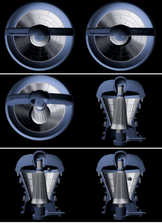
The actual minimum safe closed side setting of a crusher will vary somewhat, for any given crushing machine, depending upon the character of the material, the amount of fines in the feed, and whether the crusher is being operated under choke-feed or regulated feed conditions. It is possible, when all conditions are favourable, to operate gyratory crushers, with standard throw eccentrics, at smaller discharge settings than are indicated by the published tables. Generally it cannot be considered good practice to do so; and any experimentation along these lines should be accompanied by a close check on the power consumption, to make sure that the crushes is not being overloaded.
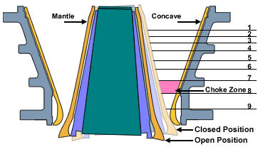
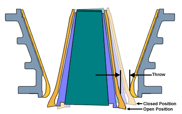
When it is necessary, or desirable, to operate a gyratory crusher at discharge settings below the minimum standard, the safe procedure is to fit the machine with a reduced throw eccentric. The crusher manufacturer will be able to advise the operator about these special throws for machines of his make.
If a reduced throw eccentric is installed, the capacity at any given setting will drop off approximately in direct proportion to the reduction in throw. In some cases it is possible to compensate, partially at least, for this drop-off by speeding up the machine. Here, again, the manufacturer will be able to advise the operator as to the maximum safe speed for any particular crusher of his line.
Another factor which governs the proportions of the crushing chamber is the maximum permissible angle between the two crushing faces. This also is subject to a certain amount of variation, depending upon the character of the material, and upon the size of the machine. Crushing angles may vary between the approximate limits of 22 and 30 degrees in a line of standard gyratory crushers. It is possible to use larger angles in the larger sizes of crushers because the greater weight of the individual pieces of material tends to minimize slipping. In these large machines, a difference of a few degrees in the crushing angle makes a considerable difference in the height, weight, and cost of the crusher.
It is obvious that the coefficient-of-friction of the material to be crushed has a very direct bearing upon the maximum permissible crushing angle. Some slippery materials, even though quite soft, require special reduced angle crushing chambers. In the standard gyratory crusher this is accomplished very simply by increasing the thickness of the concaves at the top, and tapering them down toward the discharge; in the jaw crusher the change is generally made by inserting a wedge-shaped filler behind the liner plates on the movable jaw.
For a given coefficient of friction, the harder the material is, the smaller will be the maximum permissible crushing angle. Extremely hard, tough materials even though their coefficient of friction be fairly high may require special reduced crushing angles to prevent excessive slipping. Anyone who has seen hard granite boulders shoot out of a gyratory or jaw crusher, or has watched a wide-angle crusher at work on hard granite or trap rock, has had a visual demonstration of this physical fact.
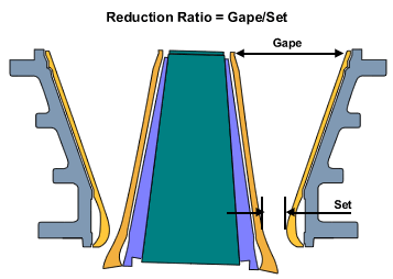
Measuring the crusher OSS CSS closed side setting
A certain amount of slippage occurs in all pressure type crushers, regardless of how small the crushing angle may be (that is, within practicable design limits), especially in the lower part of the crushing chamber where the nieces are smaller and lighter. Under normal operating conditions this tendency is counteracted by the weight of material in the upper part of the chamber. Another method of compensation is to “break” the angle of the lower tier of concaves to provide a more favorable crushing angle in this zone.
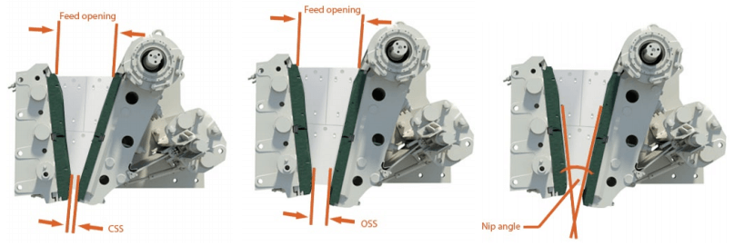
Feed opening
Feed opening (depth of the cavity) defines the maximum feed size of the crusher. In the C jaw crusher, the feed opening is measured from the top of the tooth of the fixed jaw to the bottom of the tooth of the movable jaw in a straight line perpendicular to the center line of the crushing cavity.
The maximum feed size is approximately 8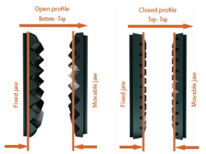 0% of the feed opening.
Open side setting (OSS)
The open side setting is measured when the crusher is at rest. The setting is measured either top to top, or bottom to top, depending on the tooth profile of the jaw dies.
Closed side setting (CSS)
The closed side setting can be calculated by deducting the stroke from the OSS. CSS is the most important crusher parameter since it defines the maximum product size and has significant bearing on capacity, product gradation, power draw, and wear.
Nip angle
The nip angle is the angle between the fixed and movable jaw dies. Too large a nip angle reduces the capacity and increases the wear as the feed material grinds and gouges the jaw dies in an upwards direction during the compressive stroke of the pitman.
