A general awakening of interest among mill men concerning the mechanical efficiencies of their crushing machines is evident from a perusal of the recent files of mining publications. Considering the large part of the power bill which must be debited to the crushing department, such interest is natural. When, however, the articles on the subject are read, the only statement upon which the writers agree is that fine grinding consumes a large amount of power, and that the machine which, from a concentration standpoint, offends as a slime producer is, for that reason, a serious offender in wasting power. When the mill man attempts to find a method for measuring the power wasted, or to compare the efficiency of one machine with that of another for the same work, he is confronted with a choice of methods which lead to conflicting results.
There are two reasons why the work of crushing is not more generally understood. In the first place, experimental data are difficult to obtain; and in the second place, before these data can be put in general form certain assumptions must be made. A difference in these assumptions by different investigators has led to conflicting conclusions. This conflict has resulted in the proposal of two laws. The first of these is the so-called Rittinger’s law, which is variously stated as follows:
“The work of crushing is proportional to the reduction in diameter.”—R. H. Richards: Ore Dressing, p. 304 (1903).
“The work required to crush rock is very nearly proportional to the reciprocals of the diameters crushed to.”—A. Del Mar: Engineering and Mining Journal, vol. xeiv, No. 24, p. 1129 (Dec. 14, 1912).
“The work done in crushing is proportional to the surface exposed by the operation, or better expressed for this purpose, the work done on a given mass of rock is proportional to the reciprocal of the diameter of the final product, assuming that all the mass has been reduced to one exact size, which is only theoretically possible.”— A. O. Gates: Engineering and Mining Journal, vol. xcv, No. 21, p. 1039 (May 24, 1913).
Of this law as variously stated above H. Stadler says: (Grading Anlayses and Their Application, Author’s Reply to Discussion, Transactions of the Institution of Mining and Metallurgy, vol. xx, p. 426
[1910-11]).
many mining engineers still have blind faith in an old blunder which, under the name of Rittinger’s law, has been thoughtlessly reprinted and carried on in edition after edition of mining books since the days of the ‘Dark Ages’ (1850).
This ‘law’ is a myth which has never been recognised by science, and it is unfair to Rittinger’s memory to connect his name with what is clearly nonsense, the currency of which, in the mining world, is due either to misunderstanding or the error of a translator. All that Rittinger himself really said on the laws of crushing, in his famous book on ore-dressing, fills barely two out of about 600 pages, and in these two pages be says clearly: ‘the increase of the surfaces exposed is directly proportional to the force required for reducing.’ (These words are also in the original text printed in italics.) As Rittinger goes on to say: ‘and therefore also to the work absorbed in effecting the separations,’ it may certainly be taken for granted that he supposed the force acting in the fracture planes themselves. Now, this may be conceivable for chemical, electrical, thermal actions and reactions, but not for external forces as applied in mechanical crushing. Had Rittinger stated that the increase of surface is proportional both to ‘force’ and to ‘work done,’ he would have been guilty of mistaking ‘force’ and ‘work done’ as identical. Rittinger’s law, therefore, simply states the proportion of the increase of surface to the force required in crushing and not also to the energy absorbed, which, in conformity with Kick’s law, varies as the volumes.”
Kick’s law is stated as follows:
“The energy required for producing analogous changes of configuration of geometrically similar bodies of equal technological state varies as the volumes or weights of these bodies.”—H. Stadler: Grading Analyses and Their Application, Transactions of the Institution of Mining and Metallurgy, vol. xix, p. 478 (1910-11).
The writer has made a careful analysis of the proofs of the previously quoted authors and has come to the conclusion that the work of crushing is proportional to the volumes of the particles crushed, according to Kick’s law; and not to the new area produced, as stated in Rittinger’s “law.” The reasons for this conclusion follow.
Kick’s law is unquestionably correct for all substances where the changes of configuration are within the elastic limit. For perfectly elastic substances the statement holds true to final rupture, and for substances almost perfectly elastic, such as rock, the law is a very close approximation of the fact.
The behavior of structural materials under stress has been widely investigated. The accompanying phenomena are well understood and the laws controlling them are universally accepted. Briefly stated, these laws are:
Within the elastic limit of any substance the force required to produce a given deformation is directly proportional to the area of the transverse section.
The amount of deformation within the elastic limit is directly proportional to the length of the specimen and to the force applied.
The work done in producing a given deformation is the product of the average force by the distance, through which it acts.
These laws apply both in tension and in compression.
If, now, we examine the behavior under stress of some highly elastic substance, the results of the examination can be plotted according to the following characteristic curves:
Fig. 1 is a force-area diagram for a given deformation within the elastic limit of the substance. The straight line represents, of course, the direct proportion between transverse area and the force required to produce deformation.
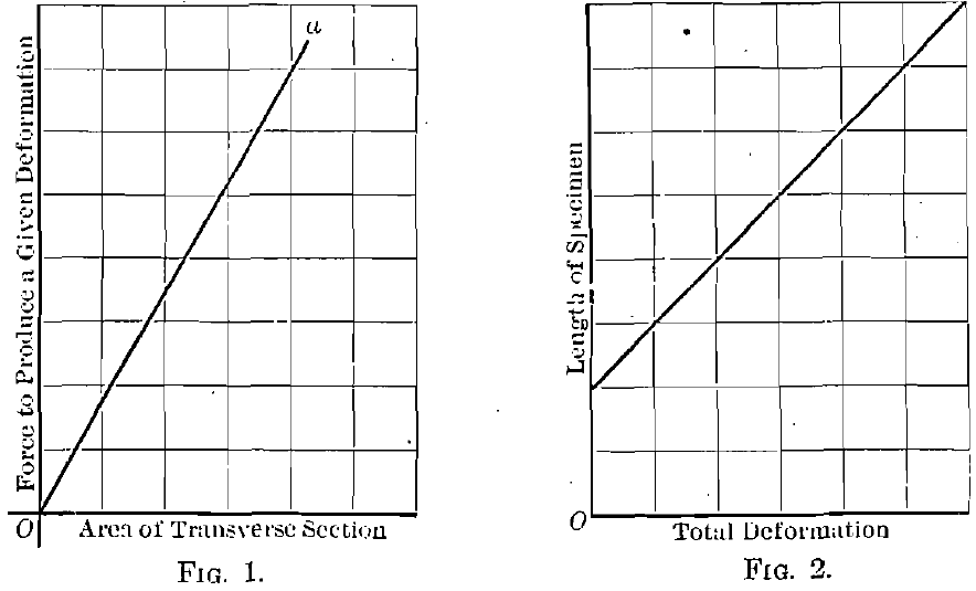
Fig. 2 represents the relation, within the elastic limit, between length of specimen and total deformation under a given load. The straight line is here the graphical representation of the law that the deformation under load is, within the elastic limit, directly proportional to the length of the specimen.
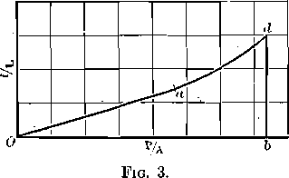
The phenomena represented by these curves are typical of all elastic substances both in tension and in compression.
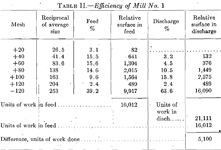
Fig. 3 gives the force-deformation diagram for a highly elastic substance. The portion of the curve, Oa, represents the behavior of the material within the elastic limit. This portion being a straight line, the conclusion is that deformation is directly proportional to the force exerted, through this portion of the curve. The point a marks the elastic limit of the material. The point d marks final rupture. From a to d unit deformation increases much more rapidly than unit stress. The total work per unit of volume to produce rupture is the area Oadb.
The preceding statements may be mathematically expressed as follows:
Within the elastic limit
f = PL/AE
W = Pf/2 = P²L/2AE = A²S²L/2AE = S²/2E x AL
When P/A = S
If, to simplify the mathematics of the demonstration, we assume the particle under load a cube of edge D, then A = D2, L = D, S2/E is an assumed constant, and
W = S²/2E x D³
or the work of deformation is proportional to the volume of the particle deformed.
For the maximum unit stress within the elastic limit
W = e²/2E x AL
or the work of deformation, at the elastic limit is proportional to the volume of the particle deformed.
It is evident from the curve, Fig. 3, that the nearer to a rupture occurs, the greater the ratio of work done within the elastic limit will be to the total work necessary to produce rupture. If a substance fractured immediately on reaching its elastic limit, the work would be represented directly by the formula
W = e²/2E x AL
The more highly elastic the substance, the more closely does the work done in rupture approximate the above formula. Thus for highly elastic

steels the force-deformation diagram is as shown in Fig. 4, and for hard rock the diagram becomes as shown in Fig. 5.
The conclusion, then, is forced upon us that the work of crushing a piece of rock is very closely represented by the formula

If we examine the proofs of Del Mar, Gates, and Professor Richards we find that the distance factor is neglected and that the formula for work takes the form
W = KP
where W represents units of work, K is a constant, and P represents the average force required to produce rupture.
Thus Professor Richards’s proof (Text Book of Ore Dressing, p. 167) is essentially as follows:
The number of planes of fracture of area one necessary to divide a cube (Fig. 6) of edge one along “n” planes parallel to a face of the cube is n — 1, and to divide the unit cube into n3 smaller cubes of equal size requires fracture along 3(n — 1) planes of area one. If the work done to produce fracture along one plane of area one is B, then the work to divide the cube of edge one into n3 smaller cubes of edge 1/n will be 3B(n — 1).
Here the error creeps in. Professor Richards says further: “Applying this to any cube where D is the diameter, of the original cube and d the diameter of the smaller resulting cubes in linear units, n becomes D/d. In making one cut through this cube, the area of fracture would be D2 and our formula now becomes, 3BD2(D/d — 1).” [In the original notation A takes the place of B in the formulae.]

This can be true only if “force” and “work done” are identical. While it is true that the work clone in producing fractures aggregating D2 in area will be 3BD2 (D/d — 1) if the work is done separately on D/1 cubes of edge one, it is not true that the work to produce a fracture of area D2 in a cube of edge D will be 3BD2(D/d — 1). The original assumption that B equals the work to produce a fracture of area one from a cube of edge one is true only if B = e2AL/2E (assuming the rock perfectly elastic). In the particular case assumed, where the edge of the cube is taken as one, B = e²(1)³/2E = e²/2E and the volume relation is lost sight of; but when the edge of the cube is assumed to be D, the work to produce fracture along a plane of area D2 is e2D3/2E and the total work required to reduce the cube of edge D to (D/d)3 cubes of edge d is 3e2/2E x D3 (D/d – 1) or the work is proportional to the volumes of the original and resulting cubes.
Gates recognizes the distinction between “work done” and “force required to do the work” and starts out with the statement:
Energy = S’F’f
when applied to the theoretical cases illustrated in Fig. 7, where S’ is the average resistance to shear per square inch, F’ is the area of fracture for one break parallel to a face in a cube of volume V, F’/4 is the area of fracture for one break in a cube of volume V/8, and f is the distance moved through by the crushing faces to produce fracture. Gates admits that within the elastic limit of the substances, f is equal to a constant times the thickness (or diameter) of the body and hence that work to compress varies as the volume of the body, but he says further, when the forces are applied until rupture occurs:
“To break the molecular bond between adjacent particles would require the same movement regardless of the thickness of the piece.”
It will not be hard to see that the distance through which the offset faces must move in either case must be the same and not proportional to the thickness of the piece.”
If Gates intends to say that the forces applied by a crushing machine are such as to produce shearing stresses of the kind he represents, he is clearly wrong. If, on the other hand, the case is one of compression between two crushing faces, and we follow his statements through to their logical extreme, we will find that a deformation which is within the elastic limit, when a cube of rock of one thickness is compressed, is greater than the thickness of some other cube. It will follow, then, that with a movement of the crushing faces equal to the thickness of the smaller piece we will admittedly cause rupture of the smaller piece, while with the same movement the deformation of the larger piece will be within the elastic limit and no rupture will occur. To cite a specific instance, let us assume two cubes of magnesian limestone, the larger 8 in. on an edge and the smaller 0.0025 in. on an edge. Trautwine (Engineer’s Pocket Book, 18th ed., p. 923) cites the result of a test by Capt. James B. Eads showing that a column of magnesian limestone 8 in. high and 2 in. in diameter shortened 0.0025 in. under pressure and recovered when relieved. If, then, we subject both of the above cubes to a crushing force which shall act through a distance of 0.0025 in., the small piece will be crushed, the large piece will not be ruptured, and the fallacy of Gates’s argument will be made apparent.
If we examine the two proofs just analyzed from another standpoint, starting with the fundamental equations:
f = PL/AE
and W = Pf/2 = P²L/2AE
if P and E are constant
W = KL/A (K = Constant = P²/2E)
on for a cube W = KD/D² = K/D
and the work done in producing a given deformation within the elastic limit is proportional to the reciprocal of the diameter of the particle deformed, which is the conclusion reached by Gates and Professor Richards.
But in no crushing machine in actual operation in the mills is the force exerted the same on pieces of all sizes. Hence the assumption that P is a constant is erroneous, and the conclusion drawn is likewise erroneous.
Before proceeding to a consideration of Del Mar’s argument in support of Rittinger’s law, an understanding of Stadler’s method of application of Kick’s law is necessary. In his paper Grading Analyses and Their Application, Stadler says:
The volumes of the particles decrease from grade to grade at the same ratio as the number of particles, constituting in their total the volume of the unity, increases, and the product of the volumes into the number of the particles of that grade is, therefore, constant for each grade. As in conformity to the above law, the amount of energy absorbed is proportional to the volume of the body to be crushed, it follows again also that the total energy required for reducing the weight of the unit is constant for each grade.
The ordinal numbers of any arithmetical progression given to these grades represent consequently the relative values of the energy which has to be spent upon producing this respective grade from the initial unit, or the mechanical value of the grade.
For obtaining the mechanical value of mixed sands, we need only to multiply the percentages of the gradings by the number of the energy units of the respective grade and add the products. .This possibility of having the gradings of pulps condensed and expressed in one representative figure proves to be of great value.
The useful work done per unit by any crushing machine is determined by the difference between the mechanical values of the samples, taken at the inlet and the discharge of the machine, and for obtaining the total work done this difference has to be multiplied by the tonnage dealt with.
The relative mechanical efficiency is the value obtained by dividing the total work done by the unit of energy (for instance, HP.):
Relative mech. efficiency = Tonnage X Work done per unit in E. U./Unit of Energy (HP.)
The use of the ordinal numbers or E. U. is illustrated in subsequent tables quoted from Del Mar’s article.
Del Mar attacks the problem by means of the “deadly parallel.” Taking grading analyses showing the results of three crushing tests, he computes the relative mechanical efficiencies according to the method of volumes (Stadler’s method) and to the method of areas exposed by crushing. In applying this latter method Del Mar assumes the relative energy unit for each grade as the reciprocal of the average size of particle in the grade. The calculations, taken from Del Mar’s article, follow:
|
Case 1 Table 1.- Screen Analyses of Mill Material |
||||
| Mesh | Mill No. 1 | Mill No. 2 | ||
| Mill Feed % | Discharge % | Mill Feed % | Discharge % | |
| On 20 | 3.1 | 15.1 | 3.5 | |
| On 40 | 15.5 | 3.2 | 35.6 | 21.2 |
| On 60 | 15.6 | 4.5 | 10.4 | 14.1 |
| On 80 | 14.6 | 10.5 | 11.1 | 17.9 |
| On 100 | 9.6 | 15.8 | 6.4 | 11.2 |
| On 120 | 2.4 | 2.4 | 0.7 | 1.6 |
| Through 120 | 39.2 | 63.6 | 20.7 | 30.5 |
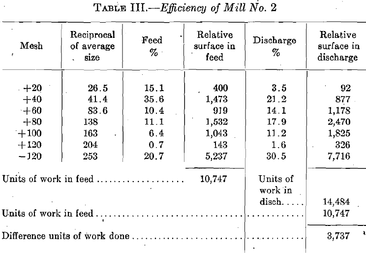
Mill No. 1 has done 5100 units of reduction with an output of 2½ tons per hp. or 5100 x 2½ = 12,750 units of reduction work, while mill No. 2 has done 3737 units of reduction with an output of three tons per horsepower or 11,211 units of reduction.
This shows an excess efficiency of mill No. 1 over mill No. 2 of 12.7 per cent.
|
Table 4.- E.U. of Mill No. 1 |
|||||
|
Mesh |
E.U. average size | Feed % | E.U. Feed | Discharge % |
E.U. Discharge |
|
+20 |
14.2 | 3.1 | 44.0 | ||
|
+40 |
16.2 | 15.5 | 251.1 | 3.2 |
51.8 |
|
+60 |
19.2 | 15.6 | 299.6 | 4.5 |
86.4 |
|
+80 |
21.0 | 14.6 | 306.6 | 10.5 |
220.5 |
|
+100 |
22.0 | 9.6 | 211.2 | 15.8 |
347.6 |
|
+120 |
22.8 | 2.4 | 54.7 | 2.4 |
54.7 |
|
-120 |
24.0 | 39.2 | 940.0 | 63.6 |
1526.4 |
| Totals | 2108.0 |
2287.4 |
|||
|
Table 5.- E.U. of Mill No. 2 |
|||||
|
Mesh |
E.U. average size |
Feed % | E.U. Feed |
Discharge % |
E.U. Discharge |
|
+20 |
14.2 | 15.1 | 214.4 | 3.5 |
49.7 |
|
+40 |
16.2 | 35.6 | 576.7 | 21.2 |
342.4 |
|
+60 |
19.2 | 10.4 | 199.6 | 14.1 | 270.7 |
|
+80 |
21.0 | 11.1 | 233.1 | 17.9 |
375.9 |
|
+100 |
22.0 | 6.4 | 140.8 | 11.2 |
246.4 |
|
+120 |
22.8 | 0.7 | 15.9 | 1.6 |
36.4 |
| -120 | 24.0 | 20.7 | 496.8 | 30.5 |
732.0 |
|
Totals |
1877.3 | 2053.5 | |||
The first example, that of the two regrinding machines using the volume method, is worked out in Tables IV and V. For mill No. 1, this difference is 179 E. U. As the work done was 2½ tons per hp-, this multiplied by 21/2½ will equal 447 E. U. For mill No. 2, the difference is 177.2. As the work done was three tons per horsepower, this multiplied by three equals 531 E. U. The work done by mill No. 2 is therefore 18% more than that done by mill No. 1, a direct contradiction of the relative efficiencies obtained by the reduction-in-diameter method.”
|
Case II Table 6.- Comparison of Single and Five-stamp Units |
||||||
|
Nissen stamp |
5- Stamp Unit |
|||||
|
Mesh |
Discharge% | Reciprocal | Mechanical Value | Discharge % | Reciprocal |
Mechanical Value |
|
+40 |
8.56 | 41.4 | 354 | 5.19 | 41.4 |
214 |
|
+60 |
13.92 | 83.6 | 1,163 | 13.75 | 83.6 |
1,149 |
|
+80 |
19.73 | 138.0 | 2,722 | 18.23 | 138.0 |
2,515 |
|
+100 |
3.40 | 163.0 | 554 | 3.21 | 163.0 |
523 |
|
+200 |
6.39 | 235.2 | 1,502 | 8.45 | 252.2 |
1,987 |
|
-200 |
43.39 | 400 | 17,356 | 48.82 | 400 |
19,528 |
|
Totals |
23,651 |
25,916 |
||||
“The single unit is a Nissen stamp of 1659 lb., 7½-in. drop at 100 per minute crushing 5½ tons per stamp per day through a 40-mesh screen. The 5-stamp unit is a fast crushing [design, 1250 lb., 7½-in. drop, 100 per minute, crushing 2.25 tons per stamp per day.”
“The Nissen stamp has done 23,651 units of reduction with an output of 5½ tons and an estimated expenditure of 4.44 hp. or
23,651 x 5½/4.44 = 29,200 units of reduction
while the 5-stamp mill has an output of 2.25 tons with 3.36 estimated hp., or
25,916 x 2¼/3.36 = 17,300 units of reduction
The mechanical efficiencies are then as 1:0.59 in favor of the Nissen stamp. The compiler of the figures stated that the power consumption was 50% less for the Nissen stamp. The above figures more than bear this out.
|
Nissen Stamp |
5-Stamp Mill |
||||
|
Mesh |
E.U. Average Size | Discharge% | E.U. Discharge | Discharge% |
E.U. Discharge |
|
+40 |
16.2 | 8.56 | 138.6 | 5.19 |
84.0 |
|
+60 |
19.2 | 13.92 | 267.2 | 12.75 |
264.0 |
|
+80 |
21.0 | 19.73 | 414.3 | 18.23 |
382.8 |
|
+100 |
22.0 | 3.4 | 74.8 | 3.21 |
70.6 |
|
+200 |
23.7 | 6.39 | 151.5 | 8.45 |
200.2 |
|
-200 |
26.0 | 43.39 | 1128.4 | 48.82 |
1269.3 |
|
Totals |
2174.8 |
2270.9 |
|||
“Table VII shows the case of the Nissen stamps working in competition with the 5-stamp unit battery. The Nissen stamp has crushed 5½ tons with an estimated horsepower of 4.44 or
2175 x 5½/4.44 = 26.94
while the 5 stamp unit has crushed 2¼ tons with 3.36 hp. or
2271 x 2¼/3.36 = 15.2
The two mills then have done work in the ratio of 1:0.56, nearly the exact ratio found by the previous calculation, using the reduction by diameter.
“Having considered the case of crushing from an impartial standpoint, it has been found that in two cases under review the results are nearly identical, while in one case they are the reverse. In the case where the volume method shows the recrushing mill No. 2 to have done better work than No. 1, the actual fact is that mill No. 1 does better work as shown by the reduction-of-diameter method.”
The last statement is due to an error by Del Mar in the use of the term “relative energy” as defined by Stadler. The difference in E. U. as developed by Del Mar (179 and 177.2 respectively) represents relative energy units per unit of weight, in this case the ton. The total relative work in each case is, then, the product of the relative work per unit of weight multiplied by the number of units of weight, or 13,425 and 13,215 respectively. This shows the relative work done in mill No. 1 greater than that ill mill No. 2, as in Del Mar’s method of calculation. The relative mechanical efficiencies obtained by the two methods are contradictory, as Del Mar remarks.
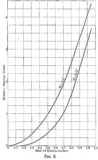
Part of the confusion that exists on this subject is due to the close agreement in the values of work over a certain range of the calculations under both methods. The reason for this apparent agreement is to be found in the graphs representing the two formulae. The formula for work proportional to area of fracture is W = KD², which plotted gives a parabola. The formula for work proportional to volume is W = K’D³, the graph of which is a cubical parabola.
In order to show the close agreement between these curves throughout a considerable range the ultimate unit stress per square inch to produce rupture in a highly elastic rock may be taken as 10,000 lb., and the deformation per inch of length from Eads’s figure before cited as 1/3200 in. The volume formula then becomes
W = 3.13 D³
In order to bring the formula for work as advanced by Gates into as close agreement with this formula as possible it is assumed that in the case cited by Eads rupture would have taken place with a very slightly greater deformation than he gives, say 0.0004 in. per inch. The formula then becomes
W = 4 D²
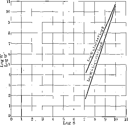
The graphs of these equations are shown in Fig. 8. They are closely parallel throughout a considerable range, showing the apparent agreement mentioned. The values near the origin of co-ordinates, where the agreement of the curves is least, are difficult to show in direct plotting. Fig. 9 represents the same equations plotted logarithmically. Here the divergence in the small sizes is very marked. That this is not wholly a mathematical divergence is apparent from the following quotation from Richards’s Text Book of Ore Dressing, p. 170:
“Von Reytt has shown by a very exhaustive series of tests that the ratio of work done to increase the surface is fairly constant with coarser sizes, but that with fine sizes the increase of surface is much more rapid than the increase of work required to produce it.”
In other words, the formula W = KD2 gives high results in the fine sizes, as indicated by the upper curve, Fig. 9. If we look again at the tables given by Del Mar we see that in his second case, where the two methods agreed closely, there was but a small difference in the amount of very fine material in the two analyses given, while in his Case I there is a large difference and one of the percentages is very high. This aids the apparent agreement between the two methods of calculation in Case II and brings out the true divergence in Case I.
Summary:
The work done in producing a given deformation of any body, within the elastic limit of the substance, varies as the volume of the body deformed.
For a highly elastic substance this principle may be extended beyond the elastic limit by the assumption that the force-deformation curve beyond the elastic limit is closely represented by a continuation of the straight line which represents the behavior of the body within the elastic limit.
For rock, which is almost perfectly elastic, this assumption is correct within the limits of experimental error.
The work of crushing rock is proportional to the volumes of the particles crushed, and to the volumes of the resulting particles.
Attempts to prove the work of crushing proportional to the reduction in diameter err in one of the following ways:
- By neglecting the distance quantity in the work formula.
- By assuming that particles in a crushing machine are acted upon in such a way as to produce simple shearing stresses.
- By assuming that the force exerted is a constant.
- By confusing “force” and “work.”
The difference in the results obtained according to the two assumptions is small throughout a considerable range of sizes.
The difference is marked in the fine sizes, where the greatest amount of power is wasted.
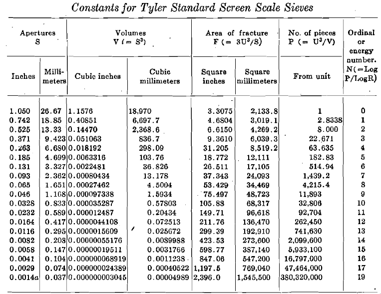
In his original paper on this subject Stadler used 1 in. as the diameter of his unit grade and a volume reduction ratio of one-half for determining the other grades. He emphasized the fact that the method of calculation is independent of the screens used, the important matter to determine being the average diameter of grain in any grade. Then, by the formula N = —10 log S, where N is the E. U. number for the grade and S is the average diameter, N may be determined. Unless, however, the screen apertures in the testing sieves used vary according to the ratio cube root of two, the values of N from Stadler’s formulae will not be whole numbers. This would be a trivial objection, since the slide rule is a part of the equipment of all mills sufficiently up to date for screen analysis, if it were not for the fact that within the last year there has appeared in this country a set of testing sieves whose apertures vary according to the ratio square root of two, and which start from the U. S. standard 200-mesh sieve, 0.0029 in. clear aperture. This makes the coarsest screen of the series 1.050 in. clear aperture. Hence for this series of sieves the E. U. numbers of the different grades based on 1 in. as a unit will be all improper fractions while with 1.050 in. taken as a unit the E. U. numbers are all whole numbers, and calculation with them is greatly simplified.
This difference in reduction ratio and unit aperture changes’ some of the formulae originally stated by Stadler, and for the convenience of those who like to know the “why” of what they are doing and have not the time always to sit down and figure it out, the following proof, in general form, of the modified formulae is appended. If we let
P = the number of pieces produced from the unit at any size,
S = sides of cubes ( = mesh apertures),
V = volumes of cubes (or weights),
F = area of fracture with reference to unit,
R = ratio of increase in volume of the particles from one grade to the next,
N = Ordinal or Energy Number (E. U.) of grades,
U = Length of edge of unit cube
the following relations are easily developed:
| P = U3/S3 |
1 |
| P = U3/V |
2 |
| S = |
3 |
| F = 3U3/S |
4 |
for F of any small cube broken from the unit equals 3(U/n)² and P = n³, S = U/n, Hence F total = 3PS² = 3n³U²/n² = 3nU² = 3U³/S.
| S = 3U3/F | (from 4) (5) |
| P = U3/S3 | (from 1) |
| S3 = 27U9/F3 | (from 5) |
Then
| P = F3/27U6 | (6) |
| V = U3/P | (from 2) (7) |
| S = | (from 3) |
| = 3/P | (from 7) |
| = U/ | (8) |
| V = S3 | (9) |
| V = U3/P | (from 7) |
| P = F3/27U6 | (from 6) |
Therefore 
For one reduction V1 = rV0
For the second reduction, V2 = rV1 = r²V0
For N reductions, VN = rNV0
But V0/VN = P
Therefore 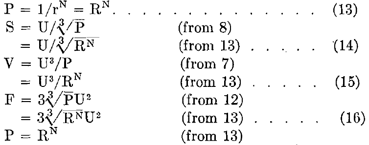
Taking logarithms of both sides:
Log P = N log R
N = (Log P)/Log R (17)
P = U³/S³ (from 1)
Taking logarithms of both sides:
Log P = Log(U³/S³)
= 3(Log U-Log S)
Therefore N = 3(Log U-Log S)/Log R (18)
P = U³/V (from 2)
Taking logarithms of both sides:
Log P = Log U³-Log V
Therefore N = (3 Log U – Log V)/Log R (19)
P = F³/27U6 (from 6)
Taking logarithms of both sides:
Log P = (Log F³/27U6)
= Log F³ – Log U6-Log 33
= 3(Log F – 2 Log U – Log 3)
Therefore N = 3(Log F – 2 Log U – Log 3)/Log R (20)
Therefore:
N = a function of V
But Work = Force X Distance
and Force varies as F
or Force = KF (where K is the average unit force to produce fracture).
Distance is a constant function of the diameter for any grade and is equal to a constant, C (determined by the modulus of elasticity of the material), times the diameter, or
Distance = CS
Therefore Work, to rupture one particle at any grade, = KFCS
But there are P particles of any given grade in the unit.
Therefore W, to crush the unit volume (or weight) at any grade, =PKFCS.
But P = U³/V (from 2)
F = 3U³/S (from 4)
Therefore W = U³ x S x 3U³ x KC/VS = 3KCU6/V
That is, W = a function of V
But N = a function of V
Then W = a function of N.
Obviously, for sizes larger than U the value of N will be negative. In such a case the mechanical value of the pulp is the algebraic sum of the mechanical values of the individual grades.
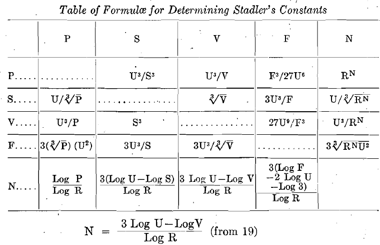
The following table gives the values of N, P, V, S, and F for the Tyler standard screen scale sieves:
The Work of Crushing, BY ARTHUR F. TAGGART,* NEW HAVEN, CONN.
