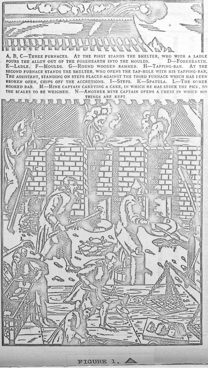
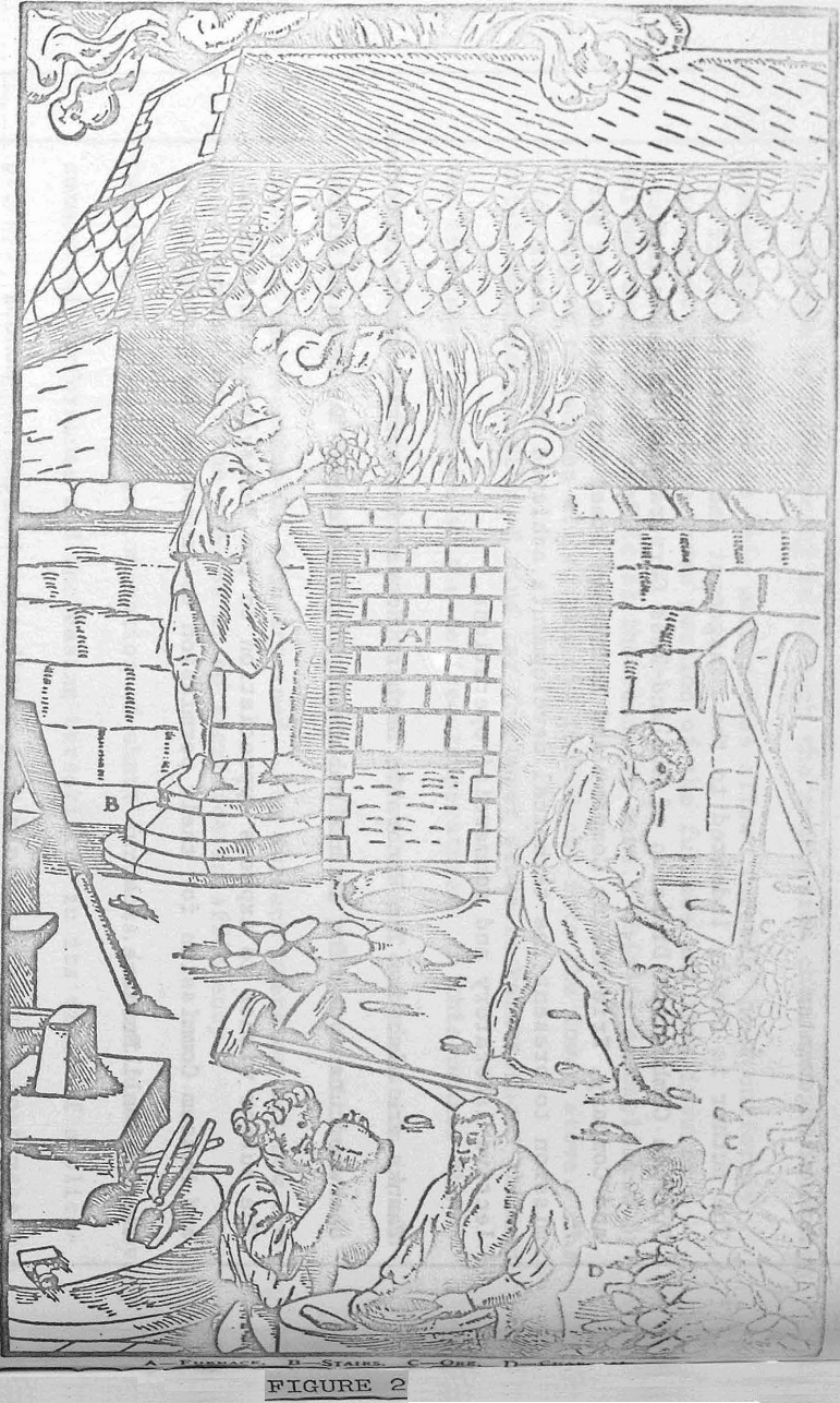
Vertical shaft furnace design and operation have their roots deep in antiquity. There is substantial evidence to indicate that iron was reduced from its oxides to serve mankind’s needs long before recorded civilization actually prior to 3500 B.C. For at least 5500 years man has been matching wits with Nature to find better methods of extracting this most common, yet essential, metal from her grasp.
The fundamental simplicity and economy of shaft furnaces continued to encourage and promote their scientific development in the smelting industry right up to today’s tremendous blast furnaces. Such a 30 ft. hearth diameter furnace capable of producing 4000 tons HM/day. This motivation has been stimulated to the point where we, in our lifetimes, will probably see more revolutionary changes in such shaft furnace design and operation than have been made in all the preceeding 5500 years of progressive evolution.
As was pointed out, the furnace is basically a gas-solid heat exchanger. The gaseous medium serves to translate heat from solid material already processed to new solids being preheated to reaction temperature. The temperature of the solids will reach a maximum when the heat capacity of the gaseous medium and the solids are equal. Since this type of furnace is used primarily for continuous processes, it becomes necessary to add the element of time. Restated then, the maximum solids temperature will be maintained in the reaction zone when the heat capacity per unit of time (mass rate in pounds per minute times specific heat in B.t.u, per pound) of the gaseous medium, equals the heat capacity per unit of time (pounds per minute times specific heat) of the solids.
The basic furnace from which all shaft furnace designs stem is the “single stove shaft” shown in Figure 5. In this furnace the charged ore or burden is introduced at the top and flows downward by gravity counter to the flow of gaseous heat transfer medium (hereafter called “wind”).
The upper portion of the furnace is used to continuously preheat the descending charge ore by the use of an ascending flow of wind. The process reaction maximum temperature occurs at an intermediate level in the shaft.
The next basic furnace in terms of relative complexity is the “two-stove furnace” shown in Figure 6. To gain more positive and more sensitive control over the principle process variable namely, temperature of the reaction zone the “make-up” fuel requirement is supplied by direct firing either solid, liquid or gaseous fuel in an external combustion chamber.
Both the upper stove and the lower stove are maintained at a heat capacity ratio of approximately one-to-one. This modification results in fuel efficiency approaching that of the simple shaft and control flexibility approaching that of the two-stove furnace, but introduces two new problems not encountered in either of the other basic types. The first of these problems is that fine dust is entrained in the preheated air when passing through the lower stove. As this entrained dust passes through the flame front it becomes soft and sticky.
The fourth type of vertical shaft furnace to be described is the so-called “two-stove furnace with auxiliary recuperator” shown in Figure 8. Here the furnace is divided into two separate and distinct compartments, one above the other, to perform the functions of heating and cooling respectively. Cooling of the pellets in the lower compartment is an entirely separate operation from the induration process and may be controlled to produce any desired pellet discharge temperature without influencing the induration in the upper compartment.
The fifth fundamental design concept also employs the use of an external dust collector and recuperator to overcome the disadvantages inherent in the three-stove design at a slight sacrifice of efficiency, but regaining complete control over temperature and wind flow distribution. Figure 9 portrays this two-stove self-regenerative principle schematically.


