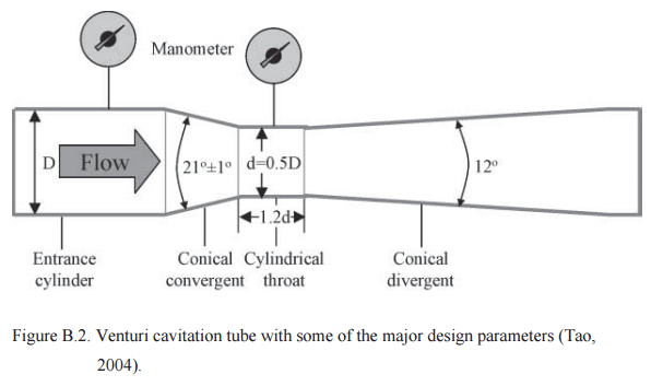
Three types of convergent sections exist in classical Venturi tubes, i.e., machined, roughcast and rough-welded. Each type specifies a set of ranges for the entrance diameter (D), the diameter (Beta) ratio (β=d/D) and the Reynolds Number (ReD). The Venturi design in this study was specified to have a smooth (machined) internal surface in the convergent section, which is especially important for calculating the discharge coefficient (C) that depends on the surface finish of this section as shown in Figure B-2. If a calculated value for D, β or ReD falls outside of the specified ranges, the
relative uncertainty of the discharge coefficient (C) increases. This can affect the pressure loss across the Venturi tube, which in our case could reduce the probability of cavitation.
Following are the list of most important design parameters for the Venturi Cavitation Tube, which includes the British Standards with some slight deviations that were applied:
- The geometric profile of the conical convergent section of a classical Venturi tube should be 21° (or ±1°),
- The length of the entrance cylinder to the conical convergent section should be equal to or greater than the internal diameter,
- The design constraints for a classical Venturi tube with a machined convergent section are as follows:
• 50 mm ≤ D ≤ 250 mm
• 0.4 ≤ β ≤ 0.75
• 2 x 10⁵ ≤ ReD≤ 1 x 10⁶
• Under these conditions the value of the discharge coefficient (C) is 0.995. - The geometric profile of conical divergent section should be between 7° and 15°, which was angled at 5° for this study.
- The length of cylindrical throat section should be equal to the internal diameter. From the pilot scale design, this section was modelled as 15% of the length of the cavitation section.
- The theoretical pressure drop is taken as the difference between the pressure reading at the entrance cylinder to cavitation tube and at the cylindrical throat, which requires two gauges for the accuracy of pressure measurement. In this study, the main concern was not to determine the flow rates but to generate cavitation on the coal particles. As a result a single pressure tapping was placed at the center of the cylindrical throat section.
Reference: 2013 FROTH FLOTATION PERFORMANCE ENHANCEMENT BY FEED CAVITATION AND MAGNETIC PLASTIC PARTICLE ADDITION by Mehmet Saracoglu University of Kentucky

