Table of Contents
Uranium Geology
The ore occurs as uraninite adhering to the outside of sand grains in the Wind River formation which rest unconformably upon Cretaceous shales. The ores are relatively low in clay content and generally regarded as exceptionally clean ores from the standpoint of objectionable impurities. The arkosic sands in which the ore occurs are very porous and permeable, having been laid down in scoured channels in the bentonitic clays.
Uranium Mining
Although extensive ore reserves in the area will require underground mining methods, significant ore reserves were also found near the surface which can be mined by open pit methods. All ore presently being mined by Petrotomics Company is by open pit under contract to Plateau Construction Company of Rawlins, Wyoming. Initial stripping of 2.3 million yards of overburden started in July, 1959 using Euclid TS24 scrapers and Euclid tractors for pushers. The ore zone is mined using a 2-yard Bucyrus-Erie shovel and a Koeh-ring shovel equipped with a backhoe front and also a crane front for drop ball use. Euclid trucks of 14.7 yard capacity with heated boxes are used for haulage to the mill which is one-half mile away. Ore control is stressed and accurately followed.
Future mining will utilize backfilling of the mined out pits for holding stripping waste instead of dumps. Stripping is carried out with four scrapers on two shifts. Mining is performed on day shift only. Mercury vapor flood lights are placed at essential points where night stripping is taking place. The water encountered in mining has ranged between 200 and 350-GPM and is pumped from the low point in the pit, utilizing a 40 HP pump mounted on a floating platform.
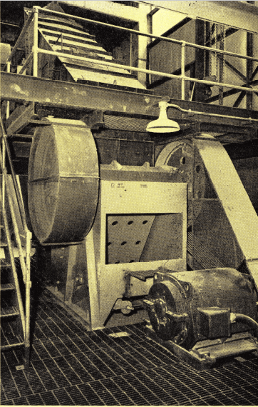
The mine-run ore, after being scalped of minus 4-inch fines, is crushed in a 30″ x 40″ Jaw Crusher. Oversize crusher was selected to accommodate large size lumps and thus avoid secondary breaking in the pit.
With the exception of occasional lenses of hard limestone, no blasting is required. The mill feed consists entirely of the ore mined by Petrotomics. The feed assays 0.25 to 0.30 U3O8, and the overall recovery is in the mid-nineties.
Uranium Test Work
The test work was performed in the metallurgical laboratories of Kerr McGee Oil Industries, Inc., near Golden, Colorado, by Mr. Emmerson Kemp, Metallurgist for Petrotomics Company and the Kerr-MeGee research staff, in cooperation with A. H. Ross and Associates, of Toronto, Metallurgical Consultants to Petrotomics. The latter are also metallurgical consultants for the operation.
Design and Construction of Uranium Processing Plant
As soon as the flowsheet was finalized in June, 1961, Stearns – Roger Manufacturing Company was engaged for the mill design and construction. Mill design and construction started immediately. Despite the severe winter, which had temperatures of 30° below zero and colder, construction was completed on schedule and milling commenced on April 5, 1962. Mr. Harry J. McMichael and Mr. Bruce H Irwin were project manager and project engineer, respectively for Stearns-Roger, and worked in close cooperation with Mr. Norman Grant and Mr. Emmerson Kemp of the Petrotomics Company and A. H. Ross and Associates during all phases of design and construction. This modern mill and flowsheet is a tribute to present day engineering practices. Simplicity was the keynote of the efficient Petrotomics Mill design.
Water
All water used in milling originates from the open pit mine. The mine water is pumped to a 5,000,000 gallon holding pond and then to an elevated 200,000 gallon water tank. The top one-half of the tank capacity is available for milling purposes. If the water level should drop to this point, there is still water available for fire protection. The water pressure in the plant is 50-psi.
Power
Power is supplied by the R.E.A. at 39,000-volts and reduced to 13,000-volts at the mill substation. All mill equipment operates at 440 and 110-volts. The mill has approximately 750 connected horsepower. A standby 250 KVA power unit is available in the mill to supply emergency power for the leach agitators, thickeners, tailing pumps, boilers, lighting, and other uses in the office, cafeteria, and sleeping quarters.
Milling
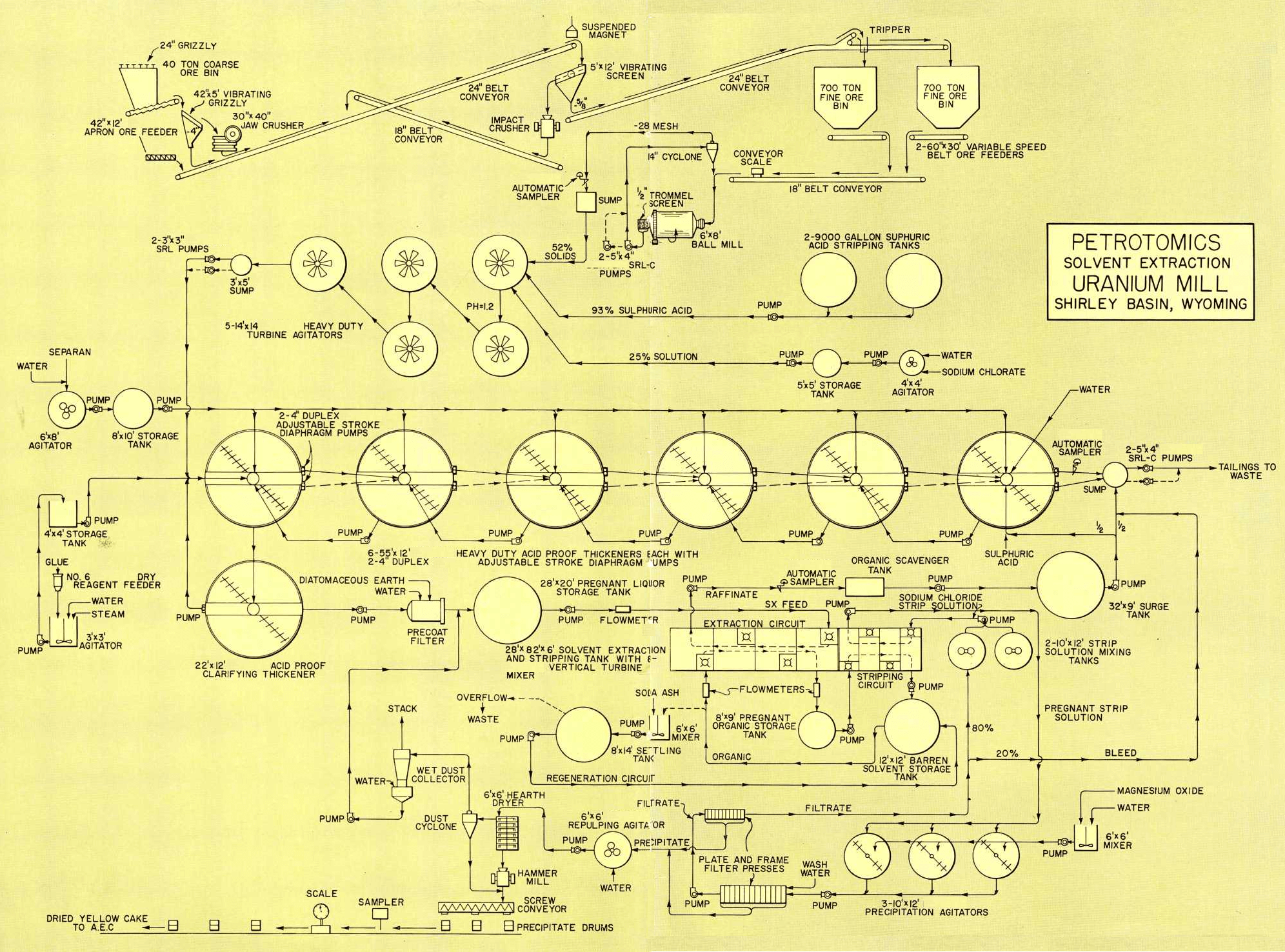
The milling process consists of crushing, grinding, acid leaching, countercurrent decantation, solvent extraction of the pregnant liquor, and precipitation as shown on the flowsheet. Additional details are given below.
Crushing
The ore from the mine is dumped directly into the 40 ton coarse ore bin using 22 ton trucks or by means of a four yard front end loader from the ore stockpiles. The coarse ore bin, which is equipped with a 24″ opening rail grizzly, is discharged by a 42″ x 12′ Apron Ore Feeder to a 42″ x 5′ vibrating grizzly with a 4″ opening. The ore is very soft and sandy in nature so a large part of the feed is immediately removed as
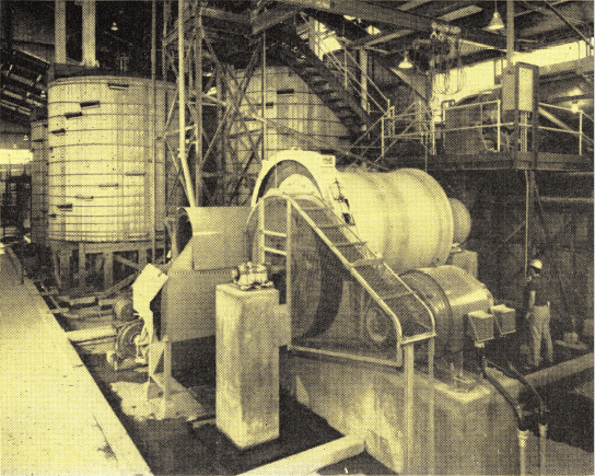
Inside the mill looking toward grinding section with the leach agitators in the background. Mill floor is on one level with operating walkways above.
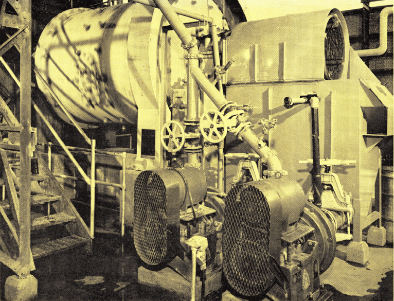
Two 5″ x 4″ SRL-C Pumps (one standby) receive the —¼” ball mill discharge and feed a 14″ Krebs Cyclone. The cyclone underflow returns to the ball mill. The cyclone overflow is minus 35-mesh and ready for acid leaching.
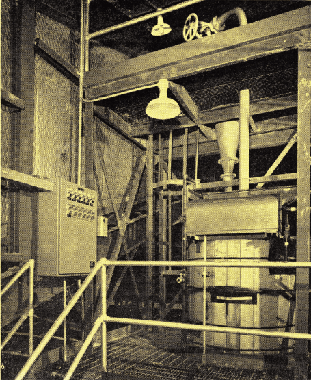
The cyclone overflow at 52% solids is sampled with a Automatic Sampler to constitute the plant head sample. Cyclone overflow, after sampling, flows by gravity to the raw leach section.
primary undersize by the vibrating grizzly. The oversize (plus 4-inch) from the grizzly passes to a 30″ x 40″ Jaw Crusher. This crusher is of much larger capacity than actually required but was selected to accommodate large size lumps and to avoid secondary breaking in the pit. A hopper with screw conveyor discharge is placed under the apron feeder to continually remove any leakage of fine sand and convey it to the primary belt conveyor.
A 24″ belt conveyor with a suspended magnet over the head pulley delivers the grizzly undersize and jaw crusher product to a 5′ x 12′ vibrating screen equipped with a 5/8″ x 5″ slotted-type screen deck. The screen oversize passes to an impact crusher and is then returned to the primary conveyor by means of an 18″ conveyor. This provides closed circuit secondary crushing operation. The vibrating screen undersize discharges to a 24″ belt conveyor with a tripper to deliver the fine ore to one of two 700-ton fine ore bins. The design capacity of the crushing plant is 125 tons per hour. The fine ore bins are of conical-shape with large area bottom openings to facilitate discharging damp ore.
No dust collection facilities are required in the crushing plant but all chutes are hooded. The mill feed sample is taken after grinding and classification.
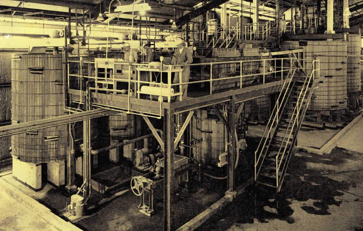
View of the leaching, precipitation, filtration, and repulping section from the mill superintendent’s office. Note one level construction with operating walkways above. Operators are shown in precipitation and filtration area. Yellow cake repulping agitator is shown directly beneath operator’s floor. The 14′ x 14′ Leach Agitators are in upper right corner. Precipitation agitators are shown in the background at the left.
Grinding Uranium
The fine ore bins are discharged by two 60″ x 30′ variable speed belt ore feeders which deliver the plant feed to an 18″ conveyor ahead of the ball mill. This belt is equipped with a conveyor scale. The 6′ x 8′ ball mill is provided with a drum feeder and discharges at 65-67 percent solids through a ¼” trommel screen attached to the mill and then to a 5″ x 4″ SRL-C Pump. An identical pump is available for standby service. The pump feeds a 14″ Krebs Cyclone which operates in closed circuit with the ball mill. The cyclone overflow is sampled with a Automatic Sampler to provide the head sample for the plant feed. The ore is ground to 35-mesh. Cyclone operates at inlet pressure of 7 psi. Cyclone overflow, all minus 28-mesh, flows by gravity to raw leach section.
Leaching Uranium
The ground ore at 52% solids enters five 14′ x 14′ Heavy Duty Turbine Agitators operating in series. The agitators provide approximately nine hours of retention time. Sulphuric acid and sodium chlorate are added to the first agitator at the rate of 60.0-pounds per ton and 2.00-pounds per ton, respectively. The resulting pH is 1.2 and EMF is 425. Provision is made so that sulphuric acid can be added to any or all agitators, but to date it has only been necessary to add the acid to the first agitator. The agitators are equipped with No. 10 Worm-Gear Reducer Drives and
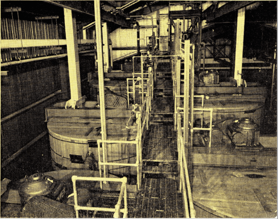
Leaching of the ground ore with sulphuric acid and sodium chlorate is performed in five 14′ x 14′ Heavy Duty Turbine Agitators. The retention time is approximately nine hours. Leach tanks are of wood and are covered. Worm – Gear Reducers are used to drive the leach agitators.
Close-up view of one leach agitator. Feed can be bypassed from any agitator without disturbing the circuit during inspection or maintenance periods. The agitators are equipped with rubber covered shafts attached to 54″ diameter, 150% pitch, six bladed, rubber covered Turbine Propellers.
rubber covered shafts attached to 54″ diameter, 150% pitch, six bladed, rubber covered Turbine Propellers. The propellers are attached to the shafts by means of an acme thread. Each agitator has a 20-HP motor. Wood tanks have 4″ nominal staves and bottoms.
The agitators are arranged so that the feed can be bypassed from any unit without disturbing the circuit during inspection or maintenance periods. An automatic pH recorder and controller is provided for regulation of optimum dissolution conditions. In excess of 97.0% of the contained uranium is dissolved in the agitators.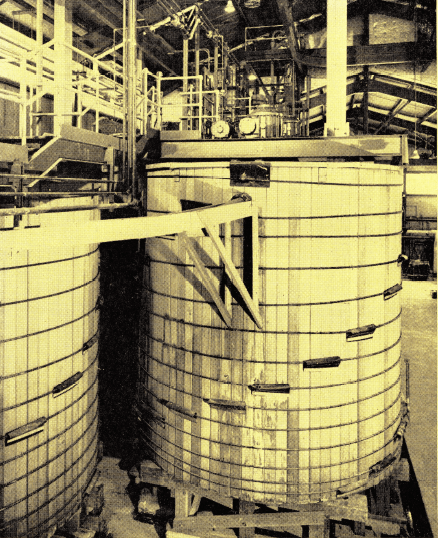
Countercurrent Decantation Washing
The discharge from the leaching circuit is delivered to the countercurrent decantation washing system using a 3″ x 3″ SRL Pump. A second identical pump is installed for standby service. The washing system consists of six 55′ diameter by 12′ deep Heavy Duty Acid Proof Thickeners. The thickeners operate at approximately 19% solids at a pH of 1.5. Each thickener is equipped with two 4″ duplex Adjustable Stroke Diaphragm Pumps (one for standby) for advancing the thickener underflows at approximately 55% solids. Approximately 100-GPM of fresh water and 100-GPM of raffinate solution from the solvent extraction system are added as wash solution to the last thickener and overflowed into 180-degree launders. The pregnant liquor overflowing No. 1 thickener contains approximately 1.5-grams U3O8 per liter.
The thickener tanks are constructed of 4″ nominal thickness wood staves. The shafts, rake arms and tie rods are rubber covered and driven by a 60″ enclosed running-in-oil Mechanism mounted on beam- type superstructures. Superstructures were fabricated and shipped in one piece to reduce installation costs. The rake blades and all wetted hardware are of 316 stainless steel. The Diaphragm Pumps have rubber lined bowls, rubber valve seats and lead impregnated ball valves. Experimental work is being conducted in the use of ceramic ball valves and results look favorable. Metal parts in contact with the acid pulp are of 316 stainless steel.
Separan NP-10 and glue are added to the thickeners as flocculants in quantities of 0.05 and 0.04 pounds per ton of solids, respectively. The Separan is prepared as a 0.25% solution. The glue is prepared as a 1.0% solution in a 3′ x 3′ agitator using a No. 6 Dry Reagent Feeder to slowly add the dry glue powder to the agitator. The only steam employed in the plant is used in preparing the glue solution.
Clarification of Pregnant Liquor
The pregnant liquor from the No. 1 thickener is further clarified in a 22′ diameter by 12′ deep Acid Proof Clarifying Thickener. The shaft and rake assembly are rubber covered and tank is of 3″ wood construction. The underflow is returned to the feed well of the No. 1 washing thickener. The overflow from the clarifying thickener is pumped to a 400-square-foot precoat filter for final clarification and stored in a 28′ diameter by 20′ deep tank preparatory to solvent extraction.
The washed underflow solids (tailings) from No. 6 thickener are sampled using a Automatic Sampler and then pumped through a 6″ wood pipe to the tailing pond approximately 1600-feet away. Two 5″ x 4″ SRL-C Pumps (one standby) are used to pump the tailings. The portion of non-cycled raffinate and bleed from the filtration circuit are added to the tailing pump sump and discarded.
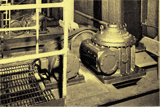
No. 10 Worm-Gear Reducers with flanged connection to agitator shafts are used. Each agitator has a 20 HP motor. Agitators are designed to start up under full load.
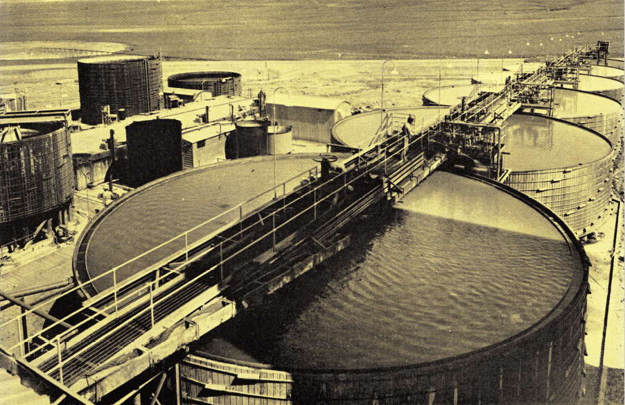
Six 55′ diameter x 12′ deep Heavy Duty Acid Proof Thickeners are used for countercurrent decantation washing of the leached solids. The shafts, rake arms, and tie rods are rubber covered to prevent corrosion from the acid pulp. The mechanisms are driven by a 60″ gear reducer mounted on beam type superstructures.
Solvent Extraction & Stripping of Uranium
The domestic uranium industry has lead the way in developing and establishing the undeniable proof that solvent extraction could be economically and technically applied to the treatment of ores and metallurgical products.
The pregnant leach solution is pumped through a flowmeter and then to the solvent extraction system. This consists of four extraction stages and four stripping stages which are all accomplished in a compartmented rectangular shaped tank measuring 28′ wide by 82′ long by 6′ high. The tank is constructed of reinforced concrete lined with fiber glass for protection from the acidic solutions. Wood weirs and PVC piping were also provided between each mixer-settler compartment. The settling compartments in the stripping section are approximately one-half the area of the extraction compartments.
The countercurrent flow of aqueous and organic in the extraction cycles is accomplished using Solvent Extraction Pumping Turbines constructed of 316 stainless steel. No auxiliary pumps or airlifts are required for organic recycle within the extraction mixers or for the advance of the aqueous and organic solutions. The flow through the extraction cycles is approximately
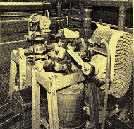
Each washing thickener is equipped with two 4″ duplex Adjustable Stroke Diaphragm Pumps. One pump is used for standby service. The pumps have rubber lined bowls, rubber valve seats, and lead impregnated ball valves. Ceramic ball valves are also being tested with favorable results.
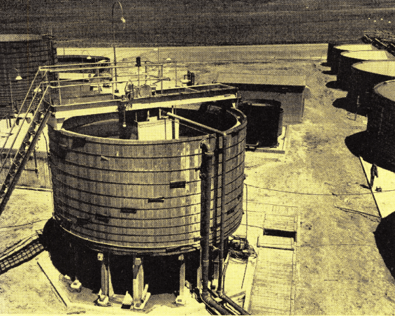
The overflow from the No. 1 thickener (pregnant liquor) is clarified in the 22′ diameter by 12′ deep Acid Proof Clarifying Thickener. The underflow is returned to the feed well of the No. 1 washing thickener. Overflow is pumped to storage and then to solvent-extraction.
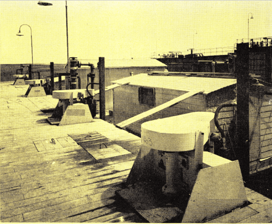
Close up view of the 28′ wide by 82′ long by 6′ high compartmented solvent extraction and stripping unit. The Solvent-Extraction units incorporate a counter-current flow principle which is accomplished without the customary acid-proof piping and pumps.
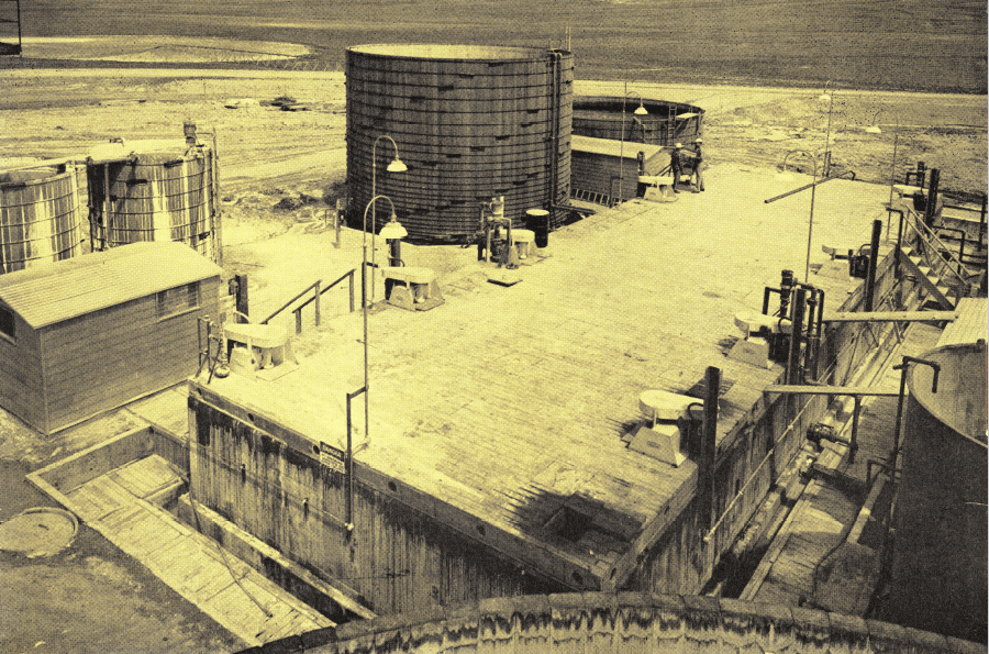
Overall view of the solvent extraction and stripping unit. The pregnant leach liquor after passing through a precoat filter is treated by solvent extraction. The countercurrent flow of aqueous and organic is accomplished using Solvent Extraction Pumping Turbines. Recovery of uranium from the pregnant leach solution by solvent extraction is in excess of 99%.
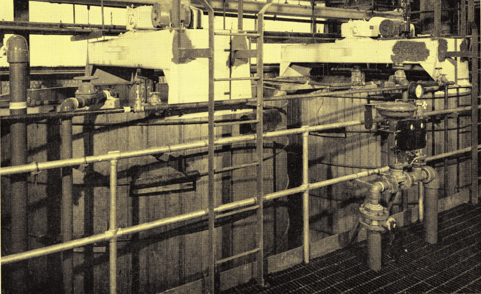
Two of the three 10′ x 12′ Precipitation Agitators are shown here. Filling, precipitation, and discharging is alternately employed for each agitator. Magnesium oxide is used to precipitate the uranium. Two slowly revolving wood paddles attached to a wood shaft by means of 316 stainless steel fittings provide the gentle action required for ideal precipitation conditions.
200-GPM of pregnant leach liquor having a pH of 1.5 and containing approximately 1.5-grams of U3O8 per liter. The organic solution consists of a mixture of 2.5% Alamine 336, 2.0% Isodecanol and 95.5% kerosene.
The raffinate (spent leach solution) is sampled with a Automatic Sampler and after passing through an organic scavenging tank is split so that one-half is used for solution back wash in the countercurrent decantation circuit and the other one-half is discarded with the tailings.
The pregnant organic solution contains approximately 2.5-grams of U3O8 per liter and represents a flow of 160-GPM. This solution enters the stripping circuit and is contacted with 1.5N sodium chloride solution strip solution having a pH of 1.5 with sulphuric acid.
Recovery of contained uranium from the pregnant leach solution by solvent extraction is in excess of 99%. The mixer-settler units used in stripping are of the same design principle as the extraction units. The Mixing-Pumping Turbines and shafts, however, are constructed of mild steel covered with 1/8″ paraline. The barren organic solution is returned to a 12′ x 12′ storage tank and reused in the extraction circuit.
Provision was made to regenerate the organic solution for removal of molybdenum but to date the content of molybdenum has been so low that regeneration has not been necessary. Nevertheless, this safeguard is available whenever required.
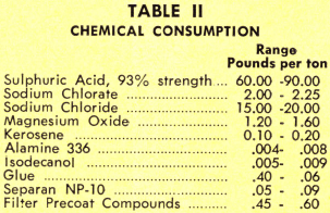
Chemical consumptions are shown in Table II.
Precipitation and Filtration
The pregnant strip solution containing 30-40 grams of U3O8 per liter and representing a flow of approximately 9.5-GPM is pumped to one of three 10′ x 12′ Precipitation Agitators. Magnesium oxide is added to a pH of 7.0 to precipitate the uranium. The precipitation agitators are equipped with two slowly revolving paddles. The shaft and paddles are of wood construction with 316 stainless steel fittings. The tanks are of wood and equipped with baffles. Filling, precipitation, and discharging is alternately employed for each agitator.
The precipitated slurry is pumped to a filter press where the yellow cake is filtered and water washed. The filtrate is refiltered in a second filter press to insure complete recovery of the solids. The final filtrate is split so that approximately 20% is bled to waste and 80% is returned to the strip solution make-up tanks.
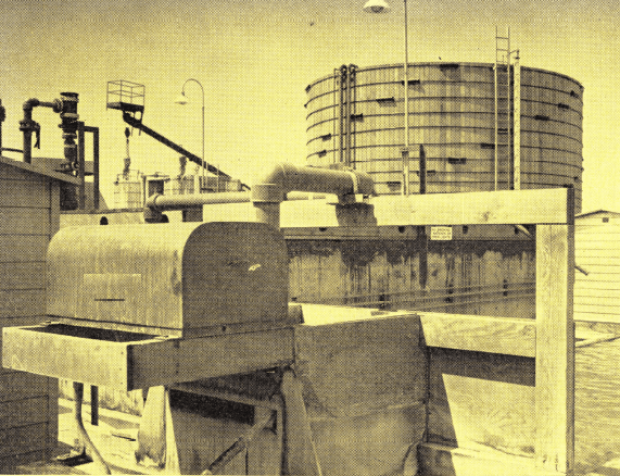
The raffinate is sampled with a Automatic Sampler ahead of the organic scavenging tank. One half of the raffinate is discarded and the other one-half is used for solution back wash in the washing thickeners.
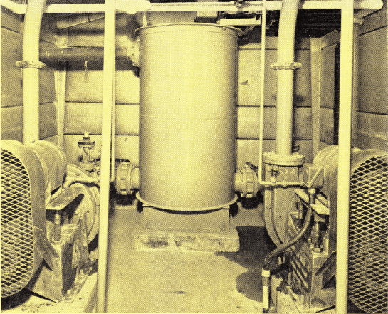
The washed tailings and waste solutions are pumped to the tailings pond using two 5″ x 4″ SRL-C Pumps. One pump is employed for standby duty. Tailing pond is approximately 1600-feet away.
Uranium Drying and Packaging
The filtered yellow cake is repulped with water in a 6′ x 6′ Vertical Turbine Agitator designed with an oversize turbine operated at slow speed to avoid breaking down the precipitate. It is pumped to a 6′ diameter by 6 hearth dryer. Vangas is used for fuel. The dried yellow cake is discharged by gravity through a small hammermill to break-up any lumps and then to a screw conveyor. Three discharge spouts are provided in the screw conveyor to automatically fill a concentrate drum and signal when it has been filled.
The exhaust from the dryer passes through a dry cyclone which removes some yellow cake and discharges into the screw conveyor. The remaining dust is removed in a wet dust collector and the slurry is pumped to the clarified pregnant liquor storage tank where the yellow cake is immediately dissolved and reprocessed through the solvent extraction system.
The drying and packaging are conducted in enclosed areas within the mill building to avoid any possible contamination of the working areas.
The drums of yellow cake are sampled, weighed, stenciled, and shipped to the Atomic Energy Commission at Grand Junction, Colorado. The yellow cake assays 88 to 89% U3O8.
Laboratory
A complete chemical laboratory is available at the mill for making all assays on ores, solutions and final yellow cake product. A metallurgical laboratory is also available for plant control studies.
Equipment Company wishes to thank Petrotomics Company for permission to describe their Shirley Basin Uranium Operation. Special thanks are extended to Mr. Norman A. Grant, Project Manager; Mr. G. K. Coates, Mill Superintendent; and Mr. Emmerson Kemp, Metallurgist and General Foreman, for their assistance in providing the information for this article. We also would like to thank Stearns-Roger Manufacturing Company for their cooperation in supplying the excellent photographs shown in this mill description.
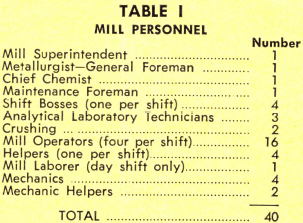
Crushing crew consists of two men. Maintenance consists of two crews comprised of two mechanics and one helper overlapping to cover the week. All are on duty on Wednesday and consequently this is the major maintenance day.
Aerial view of the 500 ton per day Petrotomics Uranium Mill with office, cafeteria, and sleeping quarters in foreground. Open pit mine is partially visible in upper right hand corner. The 5,000,000 gallon water storage pond is in the upper center. The tailing area (not visible) is 1600-feet from the last thickener. The mill design and construction were by Stearns-Roger Manufacturing Company, who supplied the photos for this article.
Introduction
The relatively recent discovery of significant uranium deposits in the Shirley Basin area of Wyoming enhanced Wyoming’s position as a major uranium producer. Extensive exploratory work starting early in 1957 confirmed the existence of substantial reserves in the Shirley Basin area and initiated the formation of the Petrotomics Company, a partnership consisting of Tidewater Oil Company, Kerr-McGee Oil Industries, Inc., Skelly Oil Company, and Getty Oil Company. The Tidewater Oil Company is the operating partner. Following the approval of an AEC milling contract, Petrotomics Company constructed a 500 ton per day acid leach-solvent extraction mill to process their Shirley Basin ores. Milling commenced April 5, 1962.
Location
The topography of the mill site area is relatively flat and is at an elevation of 7,000 feet. Casper, Wyoming, is the nearest town of significant size and is approximately 40 airline miles north of the mill. The property is accessible by road from either Casper or Medicine Bow, Wyoming, on State Highway 487 and then 15 miles of dirt road off the highway.
