Table of Contents
The principal ore deposits occur in the bands and isolated pods of tactite adjacent to the granite on the west side of the south stock.
The tactite bodies exposed around the north stock are narrow and discontinuous, although one series of lenses on the northeast side has a total length of 400 feet and averages 1 to 2 feet in width. However, these tactite zones contain too little scheelite to be economically significant.
The minerals observed in the tactite are listed in the approximate order of their abundance: garnet (andradite to grossularite, almandine), quartz, limonite, actinolite, calcite, fluorite, pyrite, pyrrohotite, diopside, sphalerite, scheelite, chlorite, hematite, clinosoisite, epidote, molybdenite, powellite, jarosite, and bismuthinite. The scheelite is buff to white; it fluoresces pale yellow to white in ultraviolet light, indicating that it contains a small amount of molybdenum.
Small lenses of both glassy and crystalline quartz occur in the tactite and in the limestone. Brecciated quartz is present at many places along the contact between the tactite and the granite, and quartz veins are common in the granite. Most of these veins contain limonite casts after pyrite. One quartz lens in the limestone contains a small amount of molybdenite and powellite.
The tactite bodies of the south stock are grouped into the following zones on the basis of their relative proximity to the granite: No. 1 or Moody zone, No. 2, No. 3, and No. 4 or Grubstake zone. The Moody zone, 6,200 feet long, with an average width of 40 feet, and the Grubstake zone, nearly 2,000 feet long, with an average width of 30 feet were the first zones that were explored or developed.
The Ore
Three classes of scheelite-bearing tactite (iron sulfide, garnet, and calcite- fluorite-chlorite) are found in the ore zones. The iron-sulfide type is a hard, dense ore containing a predominant amount of pyrite and pyrrohotite with lesser amounts of garnet and quartz. This type of tactite contains as much as 70 percent iron sulfide and is found adjacent to the granite footwall. Although usually low grade, some higher grade bands up to 5 feet in thickness may contain from 0.5 to 1.5 percent tungsten trioxide. The scheelite crystals are finely disseminated and are pinpoint in size.
The garnet type is a dense, hard, crystalline tactite consisting chiefly of garnet with smaller amounts of quartz, calcite, fluorite, and pyrite.
Marmatite occurs in the garnet tactite in local enrichments that contain 0.1 to 6 percent zinc. Scheelite, unevenly distributed throughout the ore shoots, occurs in crystals from pinpoint size to one-fourth inch in diameter. Iron-sulfide-type tactite underlies and the hornfels hanging wall overlies the garnet tactite ore shoots in the Moody zone.
The calcite-fluorite-chlorite-type ore (locally called granitite) is found where remnants of marbleized limestone occur along the hanging wall of the Moody zone. The garnet tactite forms the footwall and marbleized limestone forms the hanging wall of the granitite zones. The granitite ore shoots have been found in widths of 4 to 20 feet and extending vertically 50 to 120 feet. A relatively soft ore, it consists chiefly of calcite, fluorlte, chlorite, and minor amounts of quartz, garnet, and pyrite. The scheelite occurs in fairly large crystals. The ore varies in grade from 0.5 to 2.5 percent WO3, but the average grade is 0.8 percent. Zinc in the form of marmatite varies from 0.2 to 4.2 percent.
All three types of scheelite-bearing tactite are found in the Moody zone, but a hard tactite, principally garnet and quartz, predominates in the Grubstake zone. However, substantial amounts of granitite occur in one large shoot in the Grubstake zone. The garnet- and sulfide-type ore shoots pre-dominate in the district and have been the major producers.
Although the mine has been operated primarily for tungsten, the Wah Chang Mining Corp. has produced fluorite and zinc concentrates as byproducts. The average run-of-mine ore contained 1.2 percent zinc and from 2.5 to 4.8 percent fluorite (CaF2). The cutoff grade for the tungsten ore was 0.35 percent WO3.
Methods of Exploration
The more continuous ore shoots were found in the Moody zone, and the best ore normally occurred along the hanging wall. Therefore, it was standard practice to drift along the hanging wall and explore the footwall portion by drilling long holes (spaced on 20-foot centers) to the granite footwall. Sludge samples were logged and assayed at 3-foot intervals.
The Grubstake zone was explored by diamond drilling from stations cut along the Moody drifts. Favorable areas indicated by the drilling program were investigated and developed by crosscutting to the Grubstake zone and drifting on the ore. There were no standard intervals between the diamond- drill holes. The holes were spaced, as required, within a given area. EX bits giving a 7/8-inch-diameter core were used to drill. Where necessary, the holes were reamed, cased, or cemented. All diamond drilling was contracted by the Palmer Drilling Co. of Bishop, Calif.
Long-hole drilling from the Moody to the Grubstake zones was practiced in areas where the zones were not widely separated. Although long holes were drilled to depths of more than 100 feet, the best overall results were obtained in holes that did not exceed 70 feet in depth.
The exploration procedure was reversed in the areas where the Grubstake zone was first explored. The long-hole drilling and diamond-drill holes were drilled from the Grubstake zone to the granite footwall of the Moody zone.
Diamond drilling seldom gave conclusive results in the generally variable ore, and drifting or raising was often necessary to complete exploration of favorable drill-hole intersections. There was no differentiation between exploration and development headings; most of them served both purposes.
A close control of the grade of ore from all working places was maintained by various sampling methods that were used to guide mining. The mine geologist selected chip samples from all development faces, the miners took grab samples from mine cars and skips, and bimonthly the mine engineers collected grab samples of the broken ore in the stopes. Supervisory personnel maintained further control by examining the faces, muck piles, and loaded muck trains with ultraviolet lamps.
Sets of maps were maintained at the mine and included geologic plans, cross sections, and assay plans. Grade of ore and estimated tonnages were determined by combining all available information such as geological and sample data obtained from drifts, raises, crosscuts, nearby stopes, diamond-drill holes, and long-hole drilling.
Development and Mining
General Development
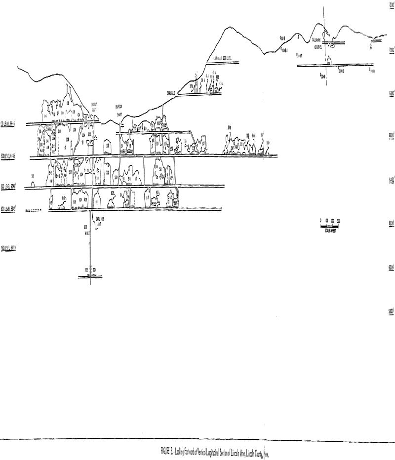
The mine was opened on the following levels: Callahan-Carlisle, 100, 200, 300, 500, 600, 750, and 900. These levels, listed in order of their increasing depth within the ore body, had a vertical range of 1,000 feet. The 100, 300, and 600 levels were opened by adit. The shallow Burdick shaft serviced the 200 level, but all ore was transferred to the 300-level through ore passes or completed stopes and was trammed to the surface. The inclined, 2-compartment, Moody shaft intersected the 100, 300, 500, and 600 levels. A 3-compartment, vertical winze from the 600 level opened the 750 and 900 levels. The mining practice maintained a level interval of approximately 150 feet (see fig. 3).
Development drifts were generally driven along the hanging wall of the Moody zone. If long-hole drilling indicated a separate footwall ore shoot, a footwall drift was driven to develop the ore. Where the ore shoots were wide enough, the main development drifts were enlarged to accommodate double tracks, which allowed preparation and drifting to proceed simultaneously.
Car-pass stations were cut at 200 feet intervals in the hanging wall of the Moody drifts. After serving their original purpose, these stations were used for diamond-drilling stations or for material storage.
Development Details
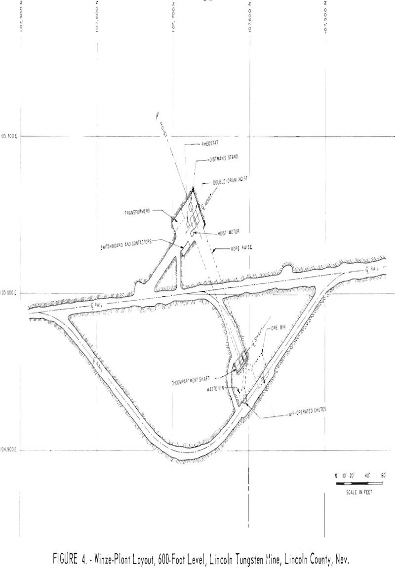
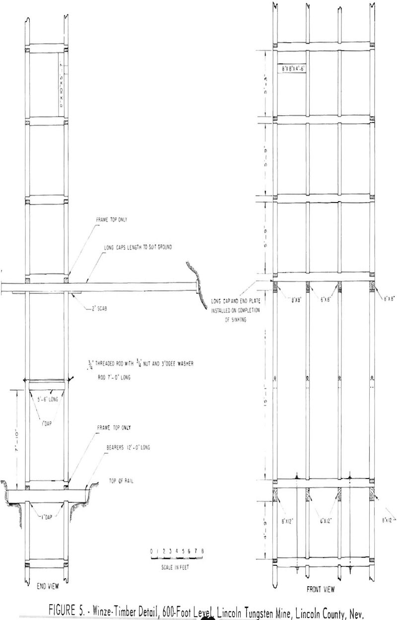
By contract the Centennial Development Co. of Eureka, Utah, sank the 600 winze. This vertical winze consisted of 2 hoisting compartments and a third compartment used for a manway, pipelines, and electrical cables (see fig. 4). Overall plan dimensions outside the timber were 15 feet 10 inches by 6 feet 8 inches. Each compartment was 4 feet 6 inches by 5 feet 4 inches inside the timber. Wallplates, end plates, and corner posts were made from 8- by 8-inch fir timber, and the center posts and dividers were made from 6- by 8-inch fir timber (see fig. 5). Timber sets were on centers of 6 feet 3 inches. Rounds were drilled with handheld Ingersoll-Rand jackhammers and were detonated electrically. A Riddell shaft mucker was used to muck the winze.
Drifts and crosscuts on the sill were driven 7.5 by 9 feet in the rock section. In most places, the drifts stood well without timber, but where ground support was required, 8- by 8-inch fir timber sets were placed on centers of 5 feet 4 inches. Gunite was used for ground that air slacked or sloughed. This ground was not heavy, and gunite was more economical to use than timber.
A Joy jumbo, mounting two 3-½-inch Ingersoll Rand DB35 drifters, was operated in the heading with the most priority. Four-winged carbide-insert bits (Copco or Timken) on 1-1/8-inch round lugged steel were used in these machines. Drilling in all other headings was done with Ingersoll Rank machines mounted on jacklegs with Atlas Copco integral steel and a carbide-insert chisel bit. An average round required 32 holes, but this number varied considerably according to ground conditions. A 5-hole burn cut was used by most of the miners. Hercules EP 160 3X powder was the principal type of explosive used. Rounds were either blasted electrically or bunch blasted with fuse primers.
Headings were mucked with Eimco 12B or 21 Rocker shovels, which loaded into 32-cubic-foot C. S. Card rocker dump cars. All track was 18-inch gage.
Two- or 3-compartment raises (6 by 6 feet per compartment) were driven for development. The manway raises at the end of each stope were cribbed. The type of round drilled depended on ground conditions and was left to the judgment of the miners who drove the raise. Drilling was done with Ingersoll Rand R-48 stopers.
Blasting at the end oi the shift was the normal practice. However, blasting on shift was permitted if it did not interfere with other work.
Stoping
The principal mining method was shrinkage stoping with drawpoint loading. A standard stope block was 100 feet long. A cribbed manway raise was carried in each end of the stope, and drawpoints were spaced on 20-foot centers. The drawpoints were cut by driving a 5- by 6-foot crosscut one round into the wall of the development drift, and then by raising a round from the end of the crosscut. The raises from adjacent drawpoints were connected and belled out. Footwall drawpoints permitted a more even draw of broken muck than drawpoints on the hanging-wall side. Drawpoint control sets of 8- by 8-inch timber were rock-bolted into place. Figure 6 shows a standard drawpoint chute. The draw was controlled by lagging held in place across the control sets by 1- by 4-inch strap iron. Eimco 12B or 21 Rocker shovels were used to muck the drawpoints.
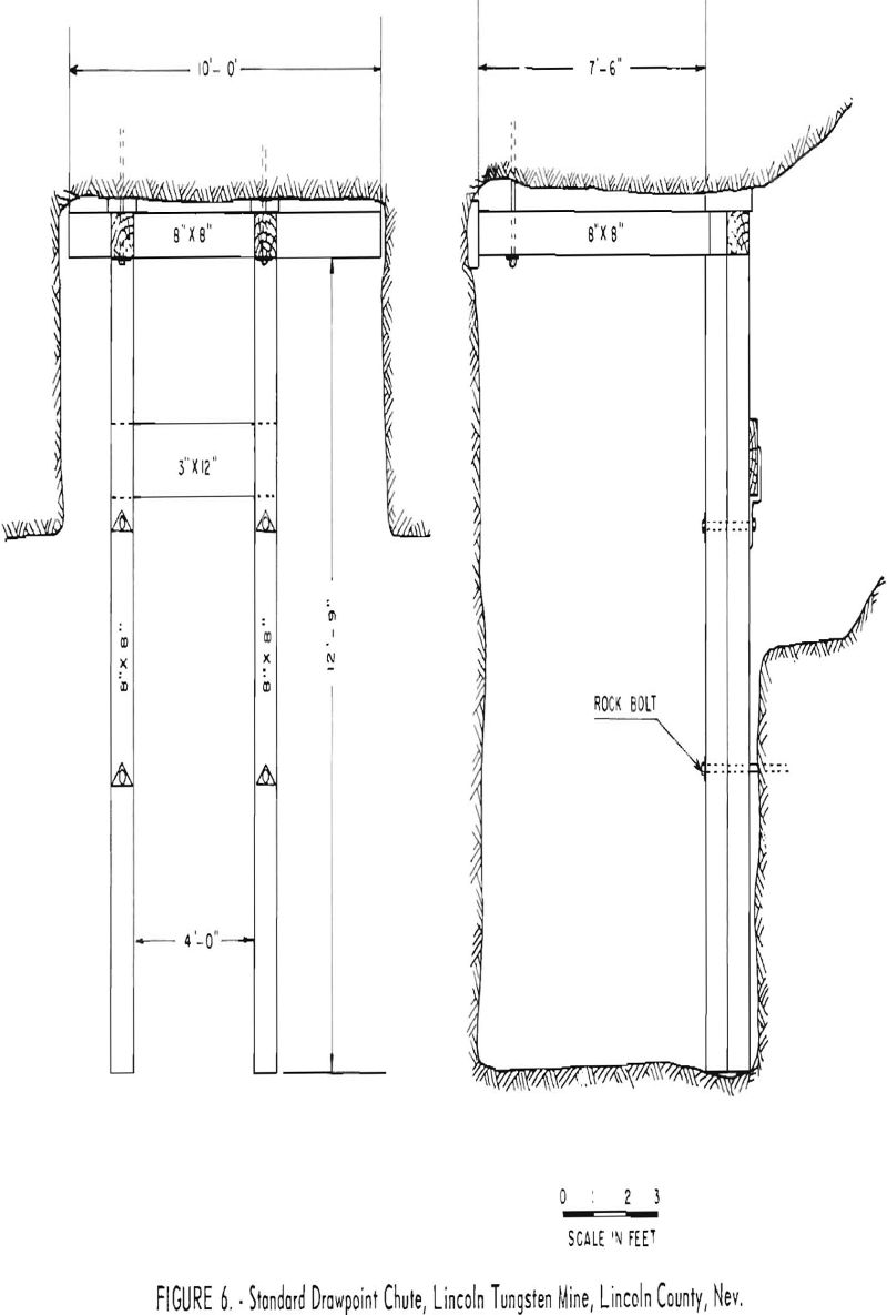
Drawing a stope through chutes was seldom practical. The tactite tended to break into large slabs and boulders that made large-scale chute loading virtually impossible. Drawpoint loading was normally used at this operation.
A 4-man crew mined a standard shrinkage stope. One man advanced the cribbed manways, 2 men drilled and blasted and another mucked the drawpoints. All stopes were mined on a single-shift basis.
Ore shoots too flat to mine by shrinkage stopes were mined by open stopes with random pillars. Manways were carried along the boundaries of the stope with raise pillars left along the manways. The stope was then prepared by driving a scram drift from the manway raise. Sill pillars of varying thicknesses were left over the haulage drifts. The stope was mined up the dip, and the broken ore was slushed to a chute or drawpoint. If the hanging wall were too weak for stoplng up the dip or toward the manways with longitudinal retreat panels, the crew provided ground support by 1-inch by 6-foot-slotted roof bolts and random pillars of waste or low-grade ore. Empty stopes were filled with waste whenever this practice was convenient. Five and 7-½ hp. air-operated slushers in the open stopes pulled 32-inch scrapers with replaceable blades.
Ingersoll-Rand jacklegs with Atlas Copco integral, carbide-insert, chisel bit steel were used for drilling in the stopes. Electric milli-second caps an Hercules EP 160-3X powder were used for blasting. Each round was lamped and marked by a mine boss who used a M12 Mineralight and aluminum spray paint to delineate the ore.
Underground Transportation
Haulage was accomplished with Mancha locomotives, 3-ton battery and 1-½ ton battery that pulled five to seven 32-cubic-foot S. C. Card rocker dump cars. On the main 600-level haulage, one 4-ton and one 2-ton diesel trammer were in use.
Ore from the 300 and 500 levels was transferred to the 600 level via ore passes. All ore passes were equipped with air-operated overshot arc gates.
The above production plus the 600- and 900-level production was trammed to the mill through the 600 adit (Carl Dice). A 4-ton Mancha diesel trammer, which pulled 12 to 20 cars performed this work. Battery trammers were used to gather haulage on the 600 level. Ore from the Callahan and Carlisle levels were trucked to the mill.
Production from the 900 level was handled through the 3-compartment 600 winze (see fig. 7). Hoisting equipment consisted of a 150 hp. double drum, Jackson foundry electric hoist. Two 43-cubic-foot Joshua Hendry skips with cages provided ample hoisting capacity.
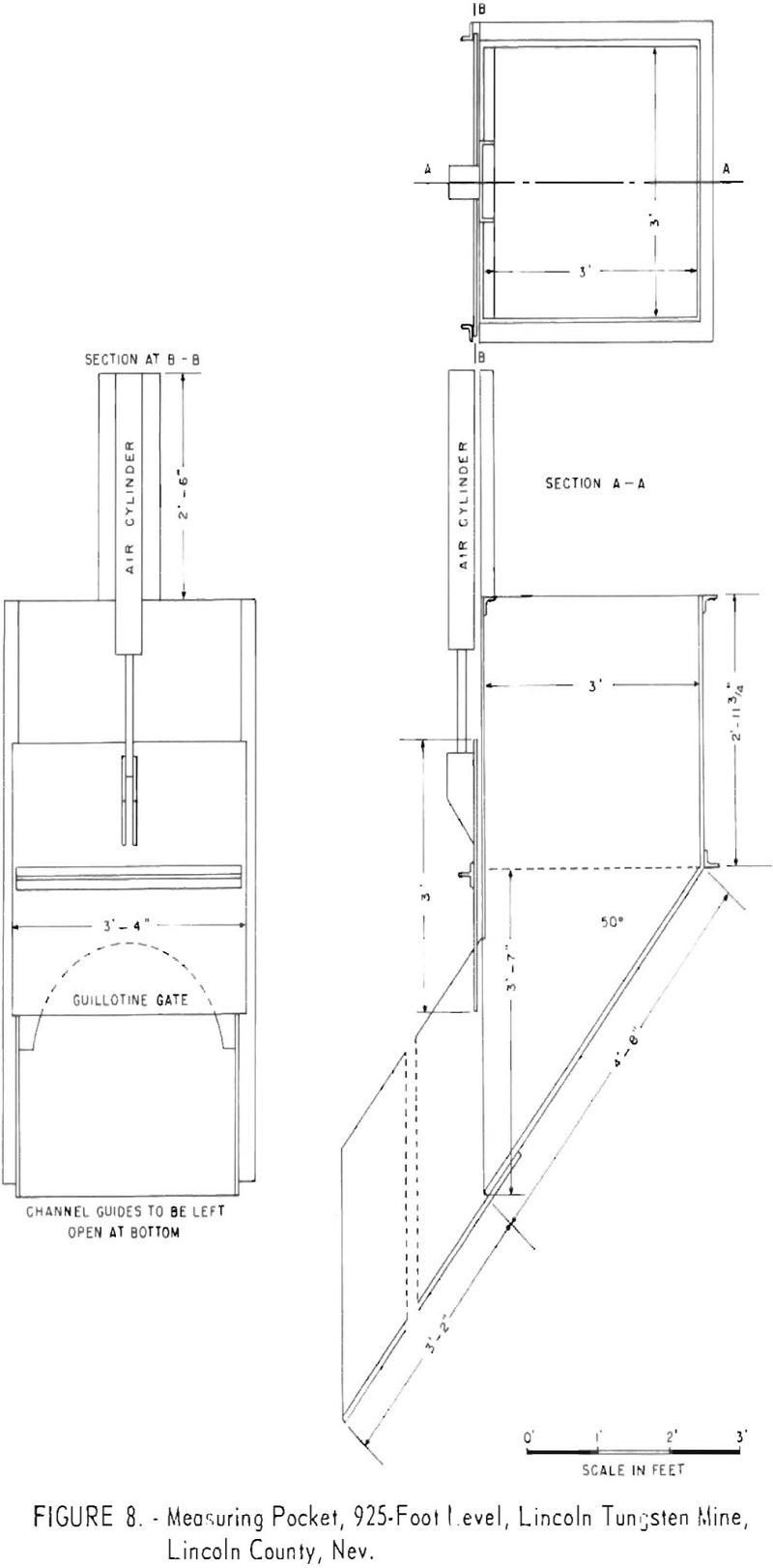
The skip loading pocket at the 925 level was composed of 2 measuring g pockets (see fig. 8), which were filled by a 20-hp. electric slusher through a scram drift from the 900 pockets. The pocket gates were air operated. Raises were driven from the 900-level pockets to the 750 level to handle ore and waste.
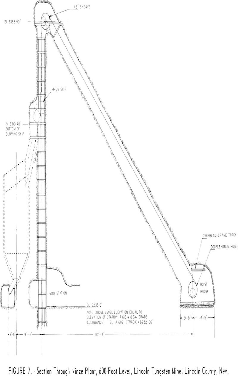
The Moody shaft was used for men and supplies to service the mine. Hoisting was done with a 50 hp. single drum, Hendrie and Bolhoft electric hoist. A company-built skip ran on a 36-inch gage track laid with 30-pound rail. A 25-foot high steel headframe supported the 36-inch sheave wheel.
Auxiliary Operations
The compressor house, hoist room, blacksmith shop, mine office, change room, and saw shed wore located at the 100-level portal area.
Compressors consisted of 1 stationary Atlas AR7, 1,750 c.f.m.; 1 stationary Ingersoll-Rand Imperial-type 10,600 c.f.m.; 3 portable Ingersoll-Rand Gyro-Flo AR600 c.f.m.; and 1 portable Worthington 550 c.f.m.
The mine shops serviced and did most repairs on rock drills, mucking machines, slushers, and other mine equipment. A machine shop at the mill site supplemented the mine shops. A 48-inch swing saw and an 18-inch bench saw were included in the saw shed.
A sectionalized mine office building contained offices for the mine superintendent, engineers, mine foreman, and shift bosses.
Mine workings provided enough water for drilling. Water for drinking and the change room was hauled to the mine from the townsite at Tempiute. This water, and the domestic and mill supply, was pumped to Tempiute from two wells in Sand Valley. A 37 hp. Byron Jackson deep-well subsmersible pump operated the No. 1 well, which was 200 feet deep with 12-inch casing. Water was pumped at 400 gallons per minute into a 20,000-gallon surge tank. Water from the second well was pumped into the same surge tank by a 75 hp. Byron Jackson deep well submersible pump rated at 1,000 gallons per minute. Two 220-hp. Byron Jackson 4-stage pumps, in series, with a rated capacity of 500 gallons per minute, or a 160-hp., 4-stage Byron Jackson centrifugal pump rated at 250 gallons per minute, pumped water from the surge tank to the camp storage tanks through a 6-inch line 26,000 feet long.
The pumps were operated on a 440-volt circuit by remote control from the mill. Power was transmitted to the pump transformers at 7,200 volts. Static head at the pump site was 1,400 feet.
Electrical power purchased from the Lincoln County Power district was transmitted at 69 kv. through a 58.35-mile, company-owned powerline to a 2,500-kv. substation at Tempiute. Power was transmitted from the substation to the mine at 7,200 volts. Mine substations supplied 440-volt 3-phase power for mine operations.
Total plant consumption per month averaged 1 million kilowatt-hours. Approximately 130,000 kilowatt-hours at a cost of 5-¾ mils per kw.-hr. with no peak load or demand charges were used at the mine.
Production
The mine was operated on a 2-shift, 6-day week basis, but operations were constant through 12 consecutive days. The total mine crew consisted of 85 men under the direction of a mine superintendent, a general foreman, a shift foreman, and 2 shift bosses for each shift.
Monthly production averaged 20,000 tons of ore with an average grade of 0.40 percent WO3. The ore-to-waste ratio was 4 to 1. Waste was gobbed in old stopes when practical.
The percentage of extraction varied with ground conditions and the distance between levels. Pillars were required in some places to provide ground support. Where possible, they consisted of low-grade ore or waste. The mine crew left small pillars between drawpoints and a 15- to 20-foot pillar between the back of a stope and the level above. The sill pillar above the stope was removed when the upper level was no longer In use. In some stopes, under favorable conditions, nearly complete extraction of ore was obtained; however, in some stopes only 60 to 70 percent extraction of the ore was possible.
Dilution became a serious problem in the more flat-lying open stopes and in ore shoots with a hornfels hanging wall. Pillars and rock bolts were used to control this situation.
Ventilation
Most of the mine workings received an ample supply of fresh air by natural ventilation. Where necessary, 5 hp. Joy Axivane fans with 12- to 15-inch vent lines were used. The air flow was upcast through the adits and up the Moody shaft in winter. The direction of air flow was reversed in summer.
Mine Drainage
Water that flowed from the 300-south level at a rate of 30 gallons per minute was collected in a sump and was then pumped by a 30 hp. Ingersoll-Rand Moto pump (2MRV 30) through a 2-inch line through M321 raise, the 200 level, and the M223 raise to the surface. A 2-inch line carried the water through the Carlisle level and up a diamond-drill hole to the 200 North Callahan level. The water was then pumped to a surface storage tank with an overflow to a second storage tank above the 100 level. Water from the second tank was taken down the Moody shaft for drill water on the 500 and 600 levels. The overflow was wasted. This installation also provided drill water for all workings above the 500-foot level except for the 200 South Callahan level.
Twenty gallons of water per minute were pumped from the 900 level and the 600 winze to a sump on the 600 level. An Ingersoll-Rand 2MRV20 pump was used for this purpose. Some of this water was returned to the 750 and 900 levels for drill water. Excess water from the 600-sump and water from the 600 level flowed out the Carl Dice adit.
Fire Prevention
A 15-man volunteer fire department provided protection from surface fires for the camp, mill, and mine. Fire hydrants and hoses were located near the surface installations. A tank truck equipped with pump and hose was also available for surface fires. Foam-type fire extinguishers were maintained in all mine buildings and at various underground sites.
A stench-warning system manufactured by Reed Engineering Co., Los Angeles, Calif., was installed to warn underground crews of fire or other emergencies. This system utilized a stench bomb connected into the air line at the compressor room. Tests that evacuated the crew from the mine proved the efficiency of the system. Chemox masks were kept in the lamp room and first-aid station for mine rescue or fire-fighting work.
Safety Methods And First-Aid Organization
Basic safety rules were explained to employees and enforced by mine supervisory personnel, and all working places were examined daily for unsafe conditions. Violators of safety rules were subject to penalties ranging from a 3-day layoff to dismissal.
A complete safety tour was made of the mini’ every two weeks. The safety committee consisted of 4 men – 2 company and 2 union representatives. After each safety tour, the committee reported its findings to the mine department. Prompt action was taken to alleviate any unsafe conditions noted in the report.
Stretchers and first-aid equipment were kept in the lamp room and first-aid stations on each level. An ambulance was maintained in the mine yard at all times. A trained nurse, In charge of a well-equipped first-aid station at the townsite, was available to give further emergency treatment.
Summary of Costs
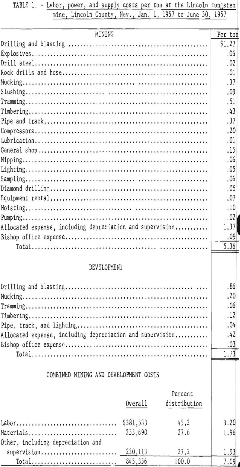
The prevailing wage rate was $2,185 per hour for miners, with time and one half paid for all work in excess of 8 hours per day or 40 hours per week. All mining was contracted. Specific mining operations were paid for on the following basis: Crosscuts, drifts, and riases by linear foot of advance; stopes by cubic foot of excavation; and mucking and tramming by the ton.
In the 6-month period, the Lincoln mine produced 119,229 tons of ore by the shrinkage-stope method of mining. Production per man-shift was 6.98 tons, and 17,071 man-shifts were worked.
Table 1 gives a breakdown by mining and development of labor, power, and supply costs per ton.
