Table of Contents
A Tower mill consists of a vertical grinding vessel provided with a central shaft screw-shaped impeller. The screw impeller rotates in such a way as to move the grinding media upward through the central portion of the grinding compartment and downward through the outer portion. Grinding media such as steel balls, ceramic pebbles, or natural pebbles, one inch in diameter or less, are charged in the grinding chamber covering the screw flight agitator. Material to be ground is fed into the top, center, or bottom of the main body depending on the application and size of the feed. As in other stirred ball mills, grinding occurs by a combination of impingement and rubbing among the grinding balls and grinding balls against screw and mill liners.
Tower Mill Circuit
The mill tested was equipped with a 20-hp 1750-rpm motor. Screw rotation was clockwise at 84 rpm. The grinding compartment was 3.1 m (10 ft) high with a diameter of 0.7 m (2.2 ft). The overall mill height was 6.4 m (21 ft). Total height of the installation was approximately 7.3 m (24 ft).
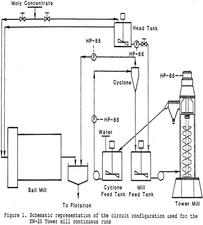
The fresh feed head tank was 0.9 m (3 ft) in diameter by 1.2 m (4 ft) high, and equipped with a ¾-hp agitator motor. Head tank underflow was fresh feed to the circuit and flowed to the mill feed tank through a flowmeter and a pneumatic control valve. Head tank overflow was routed to the No.1 regrind ball mill.
Pm = 0.9284Pe – 1.9573……………………………………………………..(1)
Pm = mechanical power delivered by the impeller (kW)
Pe = electrical power input to the motor (kW)
Test Procedures
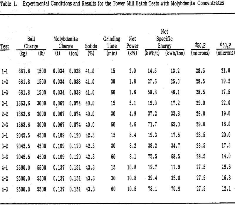
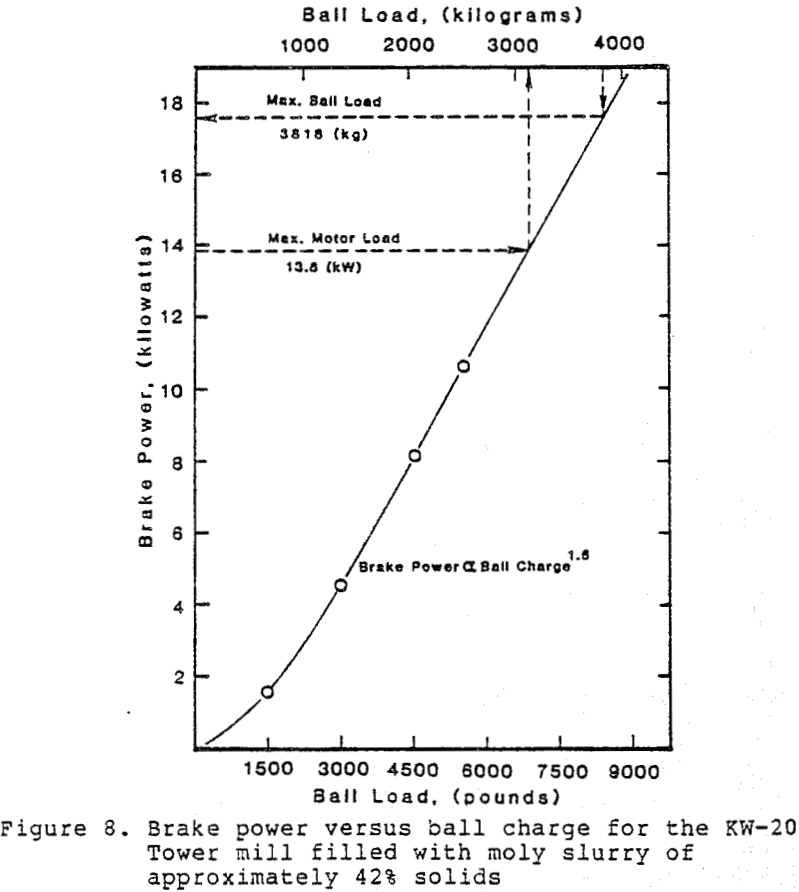
For the batch testing of the Tower mill, the mill was loaded at four different levels. In this way, four ball charges with the corresponding amounts of moly slurry were tested. These experiments were intended to show power versus charge characteristics of the mill and to determine the effect of mill charge on grinding efficiency for scale-up purposes.
Most of the samples collected were analyzed for percent solids, pulp density, and size distribution. The majority of the samples collected were size analyzed using a Leeds & Northrup Microtrac particle size analyzer Model 7991-01. These size analyses were complemented by screen analyses whenever the sample contained a substantial amount of coarse material (+150 mesh). Data analyses to obtain the product size distributions involved extrapolation and renormalization of the Microtrac data.
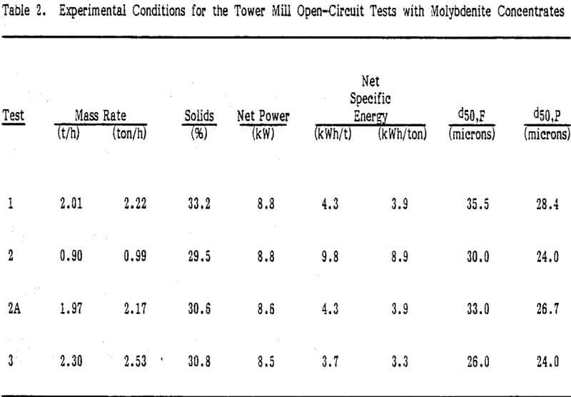
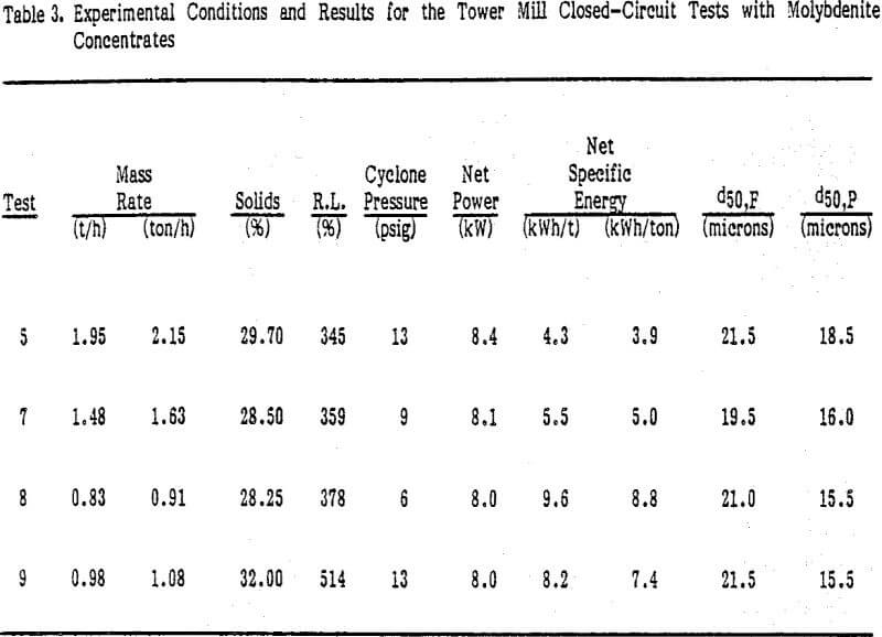
Operation of the Tower mill was initiated with four batch tests designed to determine some of the operational features of this mill. Next, four continuous open-circuit tests were run followed by four continuous
closed-circuit tests using a 10.2-cm (4-in) cyclone to close the circuit. Different strategies of operating the mill with minimum supervision for extended periods of time were attempted last.
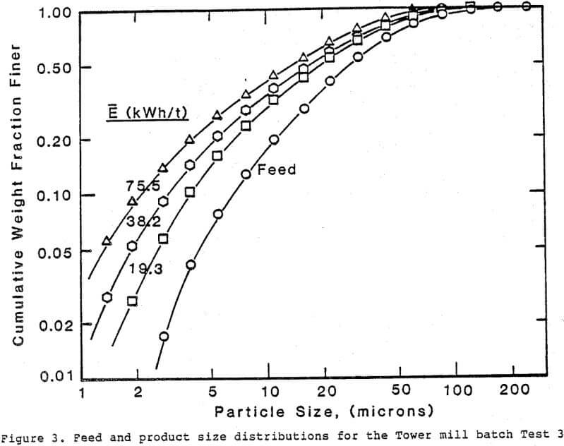
Products with a median size as fine as 12 microns were obtained from the batch tests. A decrease in net power with time was observed for all the batch tests. This behavior is caused by the disappearance of the coarse particles during the initial stages of grinding. Testing a different type of stirred ball mill.
Microscopic observation of the products obtained from the Tower mill indicated better liberation of gangue material as fineness increased. The shape of the particles was maintained as grinding progressed. Molybdenite
particles resembling thin platelets, as a result of plastic deformation during grinding, were not found.
Tower Mill On-Line Operation
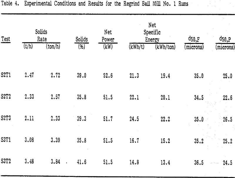
An attempt was made to operate the Tower mill circuit as a substitute for the regrind ball mill No. 1 in the moly plant. The Tower mill circuit was modified to simplify its operation so it could operate unattended. For this phase of the research, the mill was operated in open-circuit. Direct gravity feed to the mill and gravity discharge from the mill were tried first.
During this phase of the program, the grinding performance of the mill resembled that observed previously. Because of the changes in concentrate feed size and concentrate composition during normal plant operation, a comparative study at this point was not attempted. Plant performance downstream from the Tower mill seemed to be unaffected.
The power delivered to a stirred ball mill can be correlated to operating conditions using turbine mixer theory.

P = power delivered to the impeller
p = slurry density
N = impeller rotational velocity, rpm
D = impeller diameter
V = volume of the grinding vessel
K’T, KT = constants
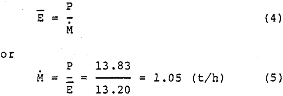
E = specific energy (kWh/t)
P = power (kW)
M = solids mill throughput (t/h)
Tower Mill Efficiency
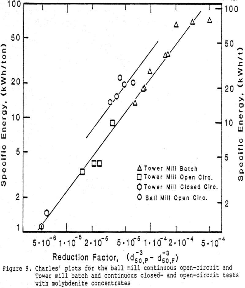
A convenient way to compare the Tower mill grinding efficiency with that of other mills is to develop a correlation between net specific energy and product size. This would be desirable not only for comparative purposes, but also for design and scale-up calculations.

E = specific energy
d50p = passing size of product size distribution
d50F = passing size of feed size distribution
A, α = constants
The fact that all data points can be represented by a single straight line of slope one ( α = 3.0 determined by trial and error) indicates that approximately the same grinding efficiency was obtained for the different tests. Fluctuation of the experimental points around the line may be caused by experimental error and/or slight changes in material hardness.
Calculations above are based on net specific energy requirements. A similar comparison between the two mills can be made using gross energy. In this case, it can be shown that 37% energy savings were obtained with the Tower mill when the gross energy consumptions were compared.
Grinding Kinetics Modeling
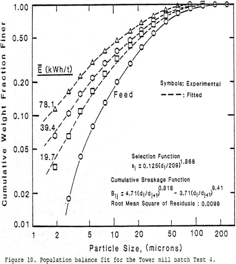
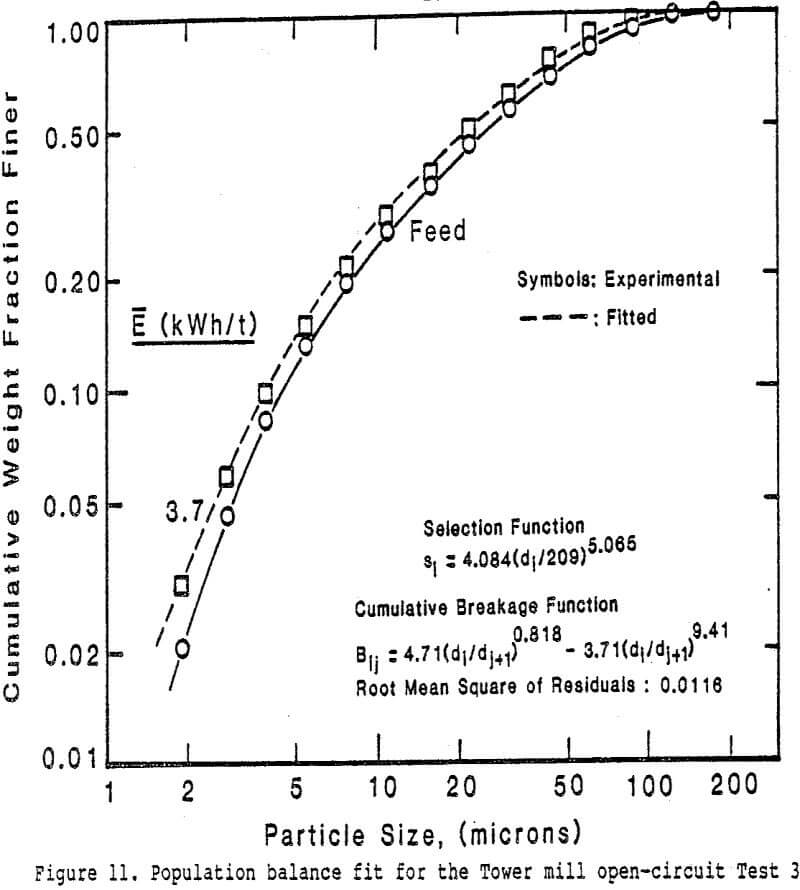
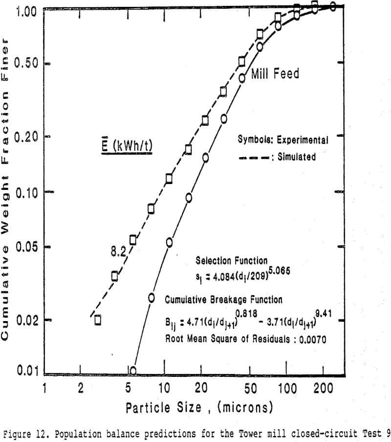
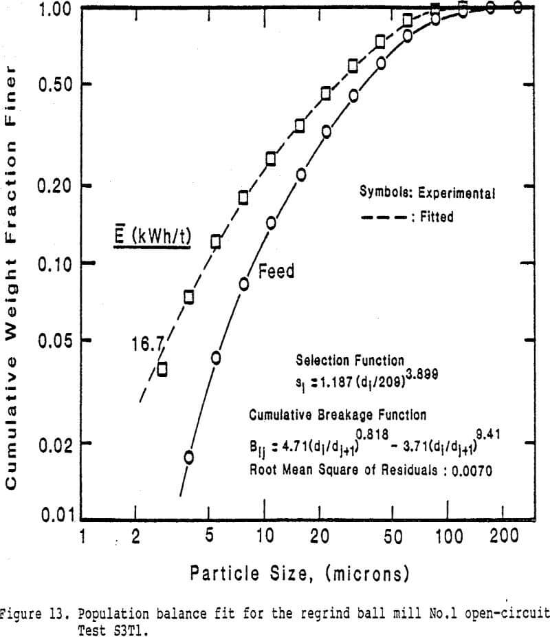
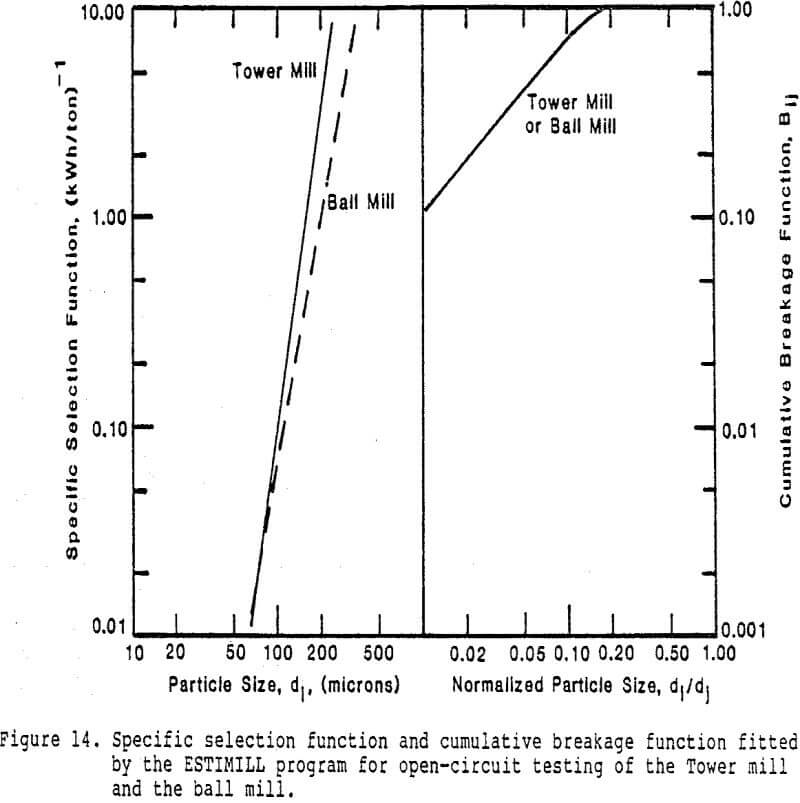
A more accurate mathematical modeling technique based on the population balance model for first-order grinding kinetics was tried to represent the Tower mill grinding behavior. This model allows for the prediction of not only the median particle size, but also the complete particle size distribution for a given set of experimental conditions and specific energy input. A solution to the mathematical equations for the model has been successfully implemented using a digital computer program named ESTIMILL.
Using the ESTIMILL program, selection and breakage functions were estimated by fitting the model to the products obtained for the batch grinding experiment performed with 2500 kg (5500 lb) of grinding media. As shown in Figure 10, very good agreement was obtained between experimental and fitted values.
