Table of Contents
A number of unique thickener mechanism designs with the operating results achieved in various installations are discussed. These unusual designs include new types of raking arms, lifting devices, and feed-wells employed to obtain higher underflow densities and minimum operator control or improved overflow clarity.
Thickening
The conventional raking arms consist of a relatively simple truss with the blades attached to the bottom chords. This design provides proper concentration of many ‘normal’ slurries. A modification of this design as shown in the center is being used with excellent results on large thickener basins where it is desirable to have a
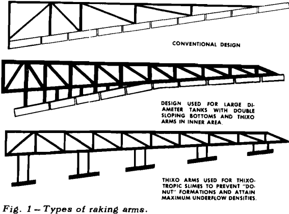
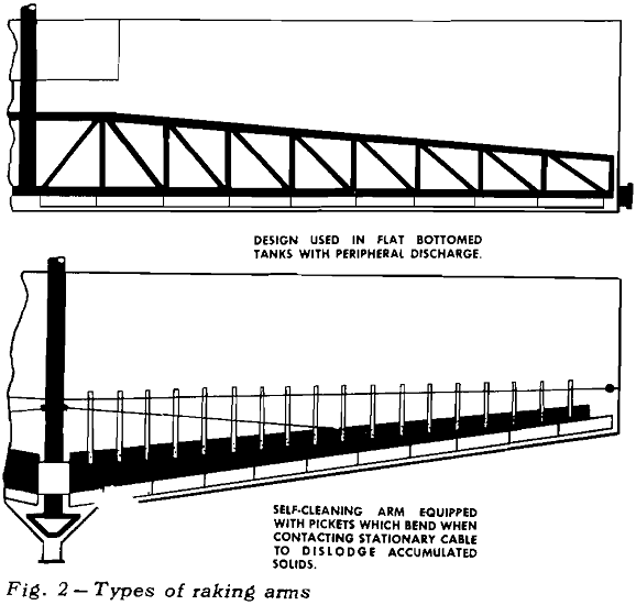
double slope to minimize overall depth of the tank while providing a steeper slope near the center to promote easier movement of coarser solids settling in this area. This configuration with Thixo Arms in the center area is used on a 325-ft diam tailings thickener at a large copper concentrator in the Southwest. The blades near the center are extended on posts so that the truss members do not move through the highest density pulp. This reduces torque load on the mechanism and promotes thickening action in this area by the well known picket principle. Underflow concentrations of 50 pct or more are being achieved regularly in this basin with no torque overloads.
Lifting Devices
In utilizing the principle of the Thixo arm to the fullest advantage, it was obvious that solids could be ‘stored’ in a thickener if a simple and effective device were available for lifting or lowering the raking arms two to five feet depending upon the volume of pulp to be stored. Accordingly, a lifting device wherein the entire mechanism is raised and lowered independently of the operation of the drive was developed.
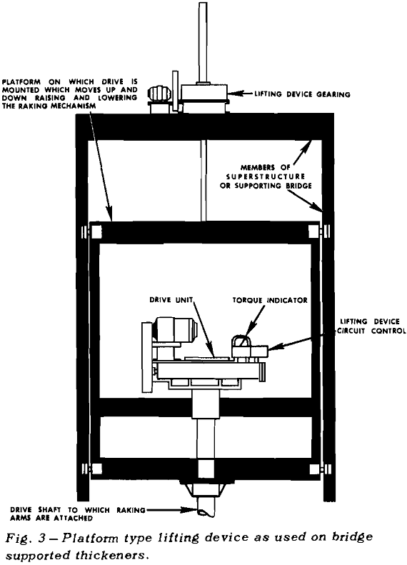
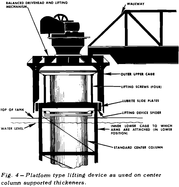
For a bridge supported mechanism where the center vertical members of the truss can be used for supporting the platform or elevator, the entire drivehead and mechanism are raised and lowered as an integral unit. On a large mechanism where bridge cost becomes excessive, the mechanism can be supported on a center column and the same lifting device principle incorporated.
The drivehead remains stationary as it is supported on a separate steel column mounted on a conventional concrete or steel center column. Telescoping cages are used to drive the mechanism, with the inner lower cage having the raking arms attached. The upper cage does not move vertically as it is bolted to the main gear of the drivehead which rotates in a horizontal plane.
Automatic Controls
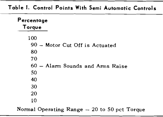
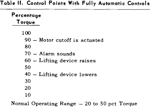
There are two basic types of controls for automatically lifting the raking arms. These generally are called semiautomatic and fully automatic. The semiautomatic controls will lift the mechanism if the torque load becomes excessive, but the arms must be lowered by the operator starting and stopping the lifting device motor. However, the semiautomatic controls often are very useful, as they will usually control the thickener operation for several hours without operator attention. This provides sufficient time to correct the cause of the overload, after which the operator has time to lower the mechanism to its normal operating position.
Clarification
In considering clarification or the removal of the finely divided solids from a slurry, the efficiency of removal often is largely a function of the flow pattern in the thickener tank. It is extremely important that the energy of the incoming flow be dissipated so that quiescent settling is obtained in the sedimentation area outside the feedwell.
The feed passes into the thickener up through the center column. At the water level it passes into the feedwell zone through a spiral inlet diffuser. This diffuser breaks the flow into a large number of streams of equal volume which flow out along the liquid level toward the feedwell. Here the flow gradually loses its velocity and changes direction, thereby dissipating the energy and distributing the flow equally throughout the basin. In this large thickener, over 90 pct of the suspended solids are removed from the feed despite the presence of very finely divided material.
Underflow Pumping Arrangements
As part of the increasing emphasis on lower installation and maintenance costs, a number of larger diameter thickeners have been installed with the underflow being removed through pipes located in the center column. On these larger units where elevating the tank is impractical because of cost and the cost of installing a tunnel is appreciable, pumping up through the center column usually is most economical. Often an access-way for a man can be provided through the column, with ample room for operating maintenance and service to the lines, should this be necessary.
A somewhat similar arrangement is used on a coal refuse thickener. The underflow from a 100 ft diam unit is discharged through a vertical underflow line which is connected to a centrifugal pump mounted just off the end of the walkway. Air operated diaphragm pumps were originally used, but the surging of flow in the line created operating problems. Since these pumps were replaced with the centrifugal type, continuous operation has been maintained without difficulty.

