Table of Contents
- Plant-Wide Control Concepts
- Plant-Wide Control System Architecture
- Process Control Strategies
- Knowledge Base Organization
- Sag Mill
- Recycle Crusher Control
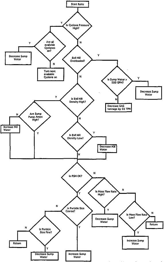
- Ball Mill
- Rougher Flotation
- Cleaner Column Flotation
- Integration of Unit Operations
- Practical Aspects of Implementation
- Personnel
- Benefits of Supervisory Control
Opportunities for maximizing corporate revenues through plant-wide process control strategies are being sought in virtually all industries. The mining industry, in particular, can realize tremendous benefits through implementation of systems that simultaneously monitor, model and optimize unit processes and their interactions. The tendency to downsize the corporate structure, improve productivity while decreasing manpower, and increase the bottom line is fueling the need for plant-wide supervisory control systems.
Plant-Wide Control Concepts
Two of the components of plant-wide supervisory control are: 1) the control strategy and 2) the control system architecture. The control strategy includes the logic, rules, procedures and actions required to control the plant. These rules, procedures and logic define the conditions and states of the plant with associated actions that govern plant performance. The control logic is not specific to any implementation software or hardware. This means that from a control logic perspective, it does not matter whether the plant has a distributed control system, programmable logic controller, stand-alone controllers or any other hardware. Furthermore, from a control logic perspective, it does not matter whether fuzzy logic control algorithms, neural networks or expert systems software are available. The control logic is the same no matter which control hardware and software are installed in the plant. The control system architecture describes the hardware and software used to configure and deploy the control logic.
The control system architecture provides an easy-to-use interface for the system that can help assure success. The control system architecture provides systems for stabilizing control and supervisory control. Stabilizing control includes the controls necessary to maintain process variables at setpoint. Stabilizing control is typically implemented using programmable logic controllers, PID controllers and distributed control systems. Supervisory control provides the ability of the control system to evaluate the plant performance and choose process setpoints that improve productivity and profitability. Expert systems, process models, optimization algorithms and economic functions are typical components of the supervisory control. Note that the distinction between stabilizing control and supervisory control raises implementation issues regarding the control strategy and control system architecture that are beyond the scope of this paper.
The control logic and data configured in an expert system is often easier to understand and modify because they are programmed in a linguistic syntax. This allows someone with process control knowledge to configure the strategy rather than requiring a computer programmer to do so. The implication is that the control logic is more easily understood by a range of managers, engineers and technicians because of the syntax. Changes in the control logic are more easily implemented because the control logic is better understood and changes are made in linguistic terms. Furthermore, the control strategy is often self documenting because of the linguistic syntax.
Expert systems implemented as part of today’s plant-wide control strategies should be object oriented. This combines the power of generalization, abstraction and classification to expert systems. The knowledge base of the expert system can be built to model the plant and implement the control system logic and data. One benefit of an object oriented expert system is the ability to configure general rules that operate on a class of objects. For example, assume that a plant has 10 identical processing lines and one processing line requires 250 rules in the control strategy. The knowledge base of an object oriented expert system would contain 250 rules, because one set of general rules written for a class of objects could be implemented. The knowledge base of a non-object oriented expert system would contain 2500 rules -10 sets of 250 rules each. When a rule needs to be modified, 10 rules must be edited in the non-object oriented expert system while only one rule must be modified in the object oriented expert system.
The design of the user interface for each plant will vary with the types of processing and number of unit operations. However, there are general principles that must be considered regarding the operator interface that will complement the control strategy and its use. Primarily, use of the operator interface should not affect the supervisory control system performance. This means that accessing process trends and other features of the user interface should not impact the speed at which the control strategy rules and procedures are evaluated. The control strategy should preempt any user interface function. This will ensure that plant operations will never be jeopardized because of user movement through the system or performance of the user interface.
A well designed and implemented graphical user interface will minimize training, improve utilization and maximize benefits of the plant-wide control system. The operator interface of a plant-wide supervisory control system should be designed and developed using a graphical approach. A graphical interface should be designed with a point and click approach. That is, the user interface contains graphics and icons built with capabilities for displaying data, trends and buttons. The user selects an icon with a mouse by positioning the mouse pointer on the icon and clicking the mouse button. When an icon is selected, the associated capability is activated. For example, the user interface may be configured with an icon of a grinding mill. When the mill icon is selected, a trend of the mill process variables may be displayed. Users and operators should not be allowed to access capabilities, features or areas of the control system that are not directly required to operate the control system. For example, operators should not be able to access configuration utilities of the system. The reason for this is to simplify use of the system, minimize user training and prevent users from entering confusing and unnecessary control system components. In a point and click interface, graphics and icons that are not required for the user to run the control system are disabled during normal operation. If the user clicks on such an icon, nothing happens.
Plant-Wide Control System Architecture
The system architecture defines the hardware and software that will house the control strategy configured in the plant-wide control system. The architecture used to design and implement a plant-wide control system often defines the ease of use, development and implementation of the system. Therefore, the system architecture should provide sufficient multi-user environment tools, computer resources, system networking and communications, fault- tolerance and system integrity.
The plant-wide supervisory control computer should be equipped with a high resolution graphics monitor. A 19- inch monitor or larger is often required to provide an easy-to-see interface. Resolution of a computer monitor is typically measured in the number of pixel elements in the vertical and horizontal direction of the screen. Monitors with 1040 vertical pixels by 1280 horizontal pixels resolution are typical. A 105-key keyboard with a mouse is used by the operator to navigate through the control system. Additionally, digital tape drives, cd-rom drives and diskette drives are available for a wide range of computer systems. Additionally, a two gigabyte digital tape drive can be installed as a backup device.
Third party applications such as database software or process models should be implemented in the supervisory control system whenever available and appropriate. The ability to implement process models in the supervisory control system provide a feed forward decision control branch that can enhance the system performance. The user interface, frequency of routine maintenance and base knowledge required to use additional software are important factors in selecting any third party application. Implementing several third party applications can create problems when the applications do not have “standard” user interfaces or require a specialized knowledge to use the application. If a third party application can be eliminated from the plant-wide supervisory control system, it should be. When a third party application is required, it should be implemented using a homogenous interface so that it is easy to use, familiar to the user and requires a minimum of training.
Process Control Strategies
A simplified process flow diagram for this concentrator is shown below; it includes two Sag mill grinding lines in closed circuit configuration. A dry crushing plant accepts the diverted screen oversize from the Sag mill circuits. Screen undersize is cycloned with fines reporting directly to rougher flotation. Primary cyclone underflow reports to a traditional closed circuit ball milling operation. The discharge of each Sag mill circuit feeds two ball mill circuits. Ball mill cyclone banks include five cyclones per cluster. Ball mill cyclone overflow reports to the rougher flotation circuits.
Knowledge Base Organization
The expert system knowledge base implementation of the unit operation control strategies is highly modular and generic in nature. Each strategy uses a combination of heuristic rules, procedures, and mathematical calculations to achieve the control objective. Object classes include process equipment, datapoints, communications and workspace icons. The process equipment classes include mills, sumps, pumps, screens, crushers, flotation cells, flotation columns and conveyors. Where applicable, the status of key objects and appropriate control actions are determined. Each control strategy determines, what if any, overloads exist and reacts to correct the overload or inform the operator of the condition.
Sag Mill
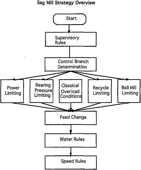
Sag mill circuit performance is the single greatest contributor to plant performance and profitability as it defines the total tonnage (and thus gross revenue) that the plant produces. Because of the direct correlation between revenue and tons processed, the objective of the Sag mill control strategy is to maximize fresh feed tonnage
In Sag mill control, bearing pressure, mill power and recycle tonnage are monitored as potentially feedrate limiting parameters. Bearing pressure represents the load in the mill which has an absolute limit at which the bearings and mill equipment may be damaged. Also, overloading the mill (as indicated by excessive bearing pressures) may result in extended down times while the mill is emptied or “inched” to restart it. Power also represents an absolute maximum which is defined by the capacity of the mill motor.
Recycle Crusher Control
The function of the recycle crushing circuit is to provide additional size reduction for the rock in the Sag mill circuit, particularly for critical size material that does not grind well in the Sag mill. Every ton that can be crushed in this circuit translates to additional fresh feed tonnage that the Sag mill can handle.
Ball Mill
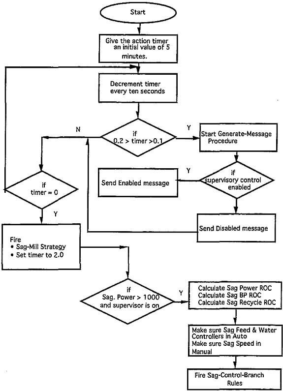
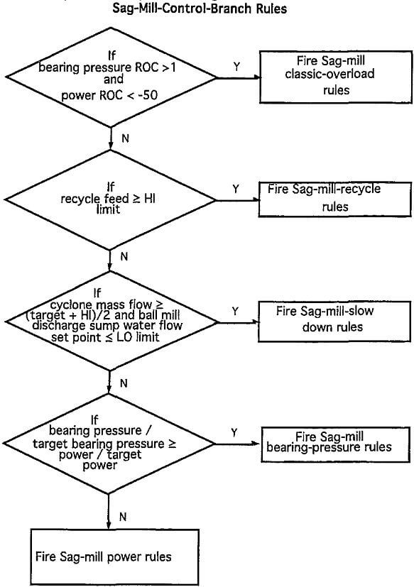
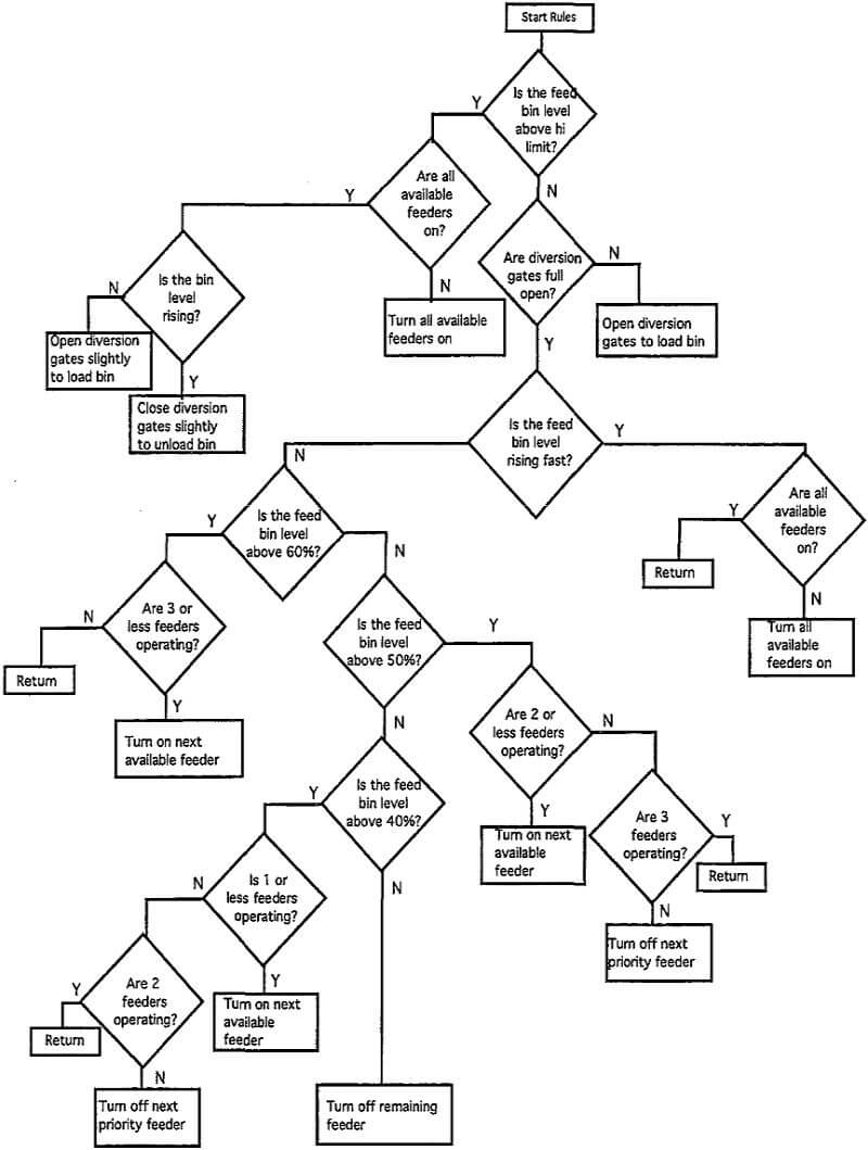
Because of its location down stream of the Sag mill circuit, the ball mill circuit has no control over the tonnage or fineness of grind which it receives. The objective of the ball mill circuit is to liberate Cu values for separation in the flotation circuit. Generally, as particle size distribution decreases, Cu liberation increases. Therefore, the direct objective of the ball mill circuit is to minimize the particle size distribution it creates. Because of the increased tonnages that may be generated from supervisory control in the Sag mill circuit, this may translate to maintaining the fineness of grind at a higher plant tonnage as opposed to decreasing the fineness of grind. During periods of hard ore when Sag mill tonnage is low, the strategy will achieve finer discharge particle size distributions, thus maximizing the benefit to the plant
Rougher Flotation
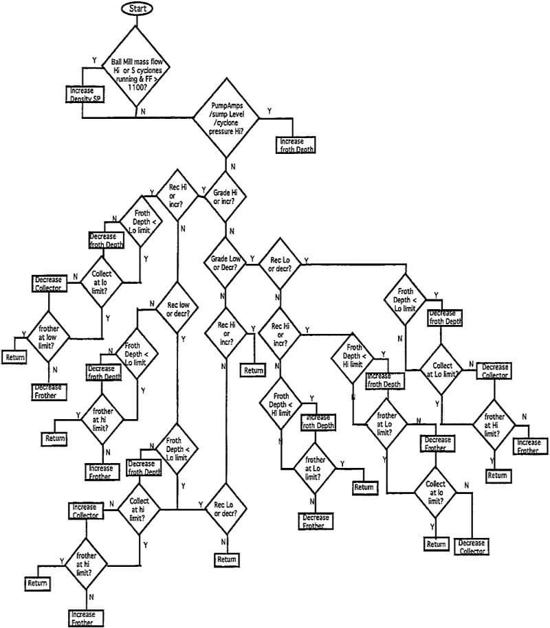
The primary objective of the rougher flotation circuit is to achieve high Cu mineral recoveries with a minimal upgrading to the rougher concentrate. Cu recovery is paramount because losses to the tailings from this circuit translate to direct losses of revenue. This is particularly significant because of the money invested in crushing and grinding this material to get to this point. Concentrate grade is less important as it will be reprocessed in several additional stages to reach final concentrate grade.
Cleaner Column Flotation
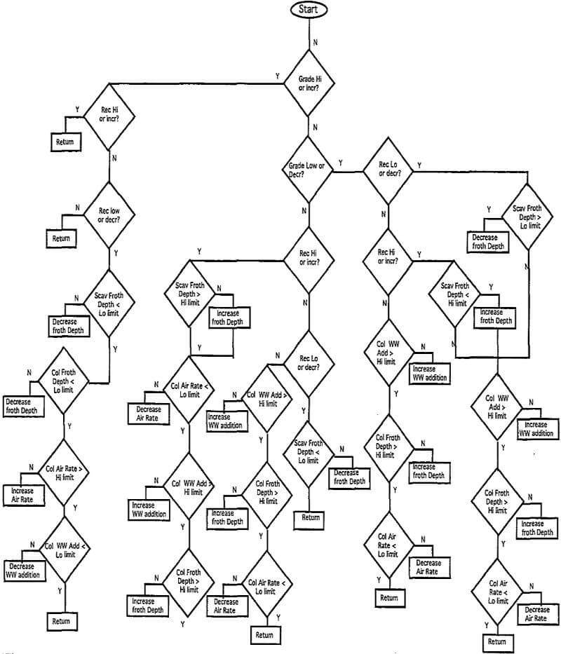
The primary objective of the cleaner circuit is to produce the highest grade final concentrate possible. As both the tailings from the cleaner scavenger cells and concentrate from the flotation columns are final products, this control strategy is constrained by limitations for both grade and recovery. Changes in cleaner scavenger tailings grade have a minor impact on overall recovery compared to changes in the rougher tailings. Therefore, Cu cleaner circuit recovery is a secondary objective to achieving final concentrate grade. Improved final concentrate grade improves profitability by reducing shipping costs, smelter charges, and smelter penalties (where applicable).
The supervisory control strategy compares the process variables with either fixed numbers or operator entered limitations to see if any emergency conditions exist. If an overload exists then the strategy adjusts manipulated variables to relieve the emergency to the extent capable within its control. If there are no overloads, then the supervisory control strategy compares the objective variables with the operator entered target values to determine the status of grade and recovery in the cleaner circuit. Based on the current combination of concentrate grade and cleaner scavenger recovery, the strategy determines which manipulated variables to adjust to help achieve the target concentrate grade and cleaner circuit recovery. The strategy then determines the magnitude of the setpoint adjustment for the chosen manipulated variable based on the rate of change of the concentrate grade or cleaner scavenger tailings. The manipulated variables (process setpoints) are then increased
Integration of Unit Operations
Because of the physical limitations, such as sump levels and pump capacity in the flotation circuit, the only significant integration of unit processes at this concentrator were between the Sag Mill and the Ball mill grinding circuits. All other circuits are controlled independently of the other control strategies. The ball mill control strategy decreases the Sag mill feedrate whenever the ball mill grinding circuit is overloaded and it has decreased the sump and mill dilution water to a minimum. In this way, the ball mill circuit limits process tonnage whenever it becomes the rate determining operation in the grinding process.
Practical Aspects of Implementation
Initial implementation of the supervisory control system at this concentrator was carried out on a Digital Equipment Micro VAX 3100. This computer had been procured previously as part of the distributed control system installation and was unused in the plant control system. Although G2 would run on the VAX 3100 computer, it soon became apparent that the VAX 3100 was not fast enough to perform real time control for multiple unit operations. With only the SAG mill control strategy installed, G2 was frequently consuming 100% of the available run time and was not able to keep up with real time. As a result, it was determined that a substantially faster processor would be required for successful implementation of the supervisory control system.
Personnel
An important challenge of implementing a plant-wide supervisory control system at this concentrator was obtaining support of the control room operators and plant engineers who use the system and are most familiar with the process. Many operators see the supervisory control system as a threat to their job or a challenge to the knowledge and abilities. Because of the key position of the control room operators in day to day operation and the plant engineers influence in process decisions, it is very difficult to implement plant-wide supervisory control without the control room operators and plant engineers support.
Benefits of Supervisory Control
The implementation of a plant-wide supervisory control system at this concentrator has resulted in both economic and non-economic benefits to the concentrator. The non-economic benefits include the following:
- Redefined the control room operator’s job to focus on overload conditions and plant operation rather than optimization.
- Standardized the plant control philosophy. The consistent application of the control strategy removes operator technique as a variable in analyzing plant operational problems. This has lead to insights on phenomena previously unexplained in the plant.
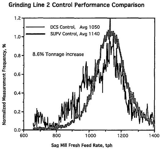
In order to evaluate the Sag mill strategy performance, a two week on/off testing program was performed immediately after implementation of the Sag mill strategy. Dat logged during the test period included: grinding circuit feed rate, water consumption, bearing pressure, recycle tonnage and power draw. Results of this evaluation indicated an average improvement in Sag mill tonnage of 10.6% for Sag mill 1 and 8.6% for Sag mill 2. These results are shown in histogram form below.
Based on plant historical data, implementation of Expert ball mill control resulted in a reduction in the average P80 of approximately 2% points. Historical data has shown that the correlation between fineness of grind and Cu recovery at this concentrator is such that 1 point finer grind corresponds to 0.5% higher Cu recovery. Therefore, this corresponds to approximately a 1.0% increase in Cu recovery.
Flotation Control
The combined implementation of rougher and cleaner flotation control resulted in the ability to reduce process pH by as much as 0.7 pH points. This was predominantly caused by control of the flotation column using air, washwater and froth depth. By actively controlling these variables, it was possible to increase crowding in the column and improve grade by nonchemical means. As a result, column lime additions were terminated and cleaner and rougher pH was decreased.
