Table of Contents
- Cone Crushers
- Cone Crushers for Sale
- Cone Crusher Hydraulic System Operation
- Fast & Easy Control Product Size
- Protect Cone Crusher from Tramp Iron
- Cone Crusher Feed Distribution
- Crusher Foundation
- Uniform Crusher Discharge Product
- Cone Crusher Dust Seal Protects From Wear
- Fast Crusher Maintenance Reduces Downtime
- CONE CRUSHER LUBRICATION SYSTEM
- Cone Crusher Eccentric Design
- TYPES of CRUSHING CHAMBERS
- HYDRO-CONE CRUSHER CAPACITIES
- Crusher Product Screen Analysis
- How to use Crusher Product Curves
- Crushing Test Laboratory & Engineering
From the discussion so far it is obvious that two energy factors determine a crusher’s productivity:
(1) Total power drawn affects the quantity produced of any given size or range of sizes.
(2) The energy applied, previously defined as the crusher’s Power Rate (kilowatt-hours per ton of feed) will determine the size reduction. This has just been clearly demonstrated by the pendulum tests.
In a previous paper, we have shown that the theoretical forces achieved in a crushing chamber are a direct result of the design geometry and driving power applied to the crusher. Machines from three manufacturers can theoretically apply different crushing forces to processed material, according to Table (1).
The energy intensity within the crushing chamber will differ for various machines. The wide range of eccentric throws and connected powers for various units will give different crushing impacts, which might be considered anologous to the pendulum. The angle of the mantle for the crushing head varies between manufacturers as does the length of the crushing zone from less than 200mm (8 inches) to more than 600mm (24 inches) but as has been indicated from the pendulum size distribution correlations it is the energy input to the feed material which determines the reduction and size distribution. Eccentric throw and chamber shape appear to have little influence.
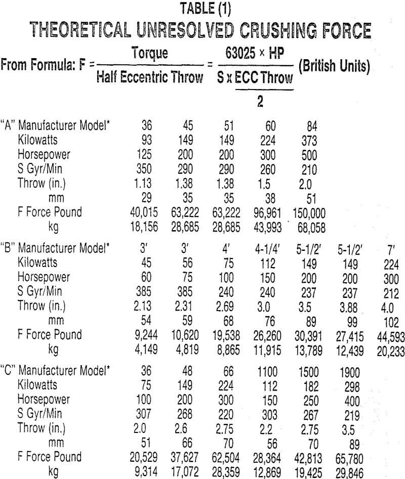
Note: Some manufacturers do not give all this specification information in sales literature, and many of these measurements here were made in the field on operating equipment. Even if correct in one instance, the specifications could be different for different machines. For accurate data, the person studying such information should refer to the crusher manufacturer.
This information is only published so the reader can get an order of magnitude comparison for setting up his own technical study.
To make the finest product, we should be running the crusher with the lowest practical feed rate and applying the maximum crushing force. This will give the highest power rate but there are physical limits to operating in this mode, especially if the crusher is run at fixed setting. To make a coarse product the power rate should be no greater than that needed to generate that size. The power drawn in any case should be maximized to yield the greatest quantity of the required product.
There has been adequate reporting by people such as Szaj and Lynch that operating crushers at fixed setting most often demands that the average operating power be limited to only 50 or 60% of that connected, to guard against crusher stalling and minimize mechanical damage. Control devices such as those by Lindgren et al have been developed to maximize power drawn and productivity through fixed setting crushers.
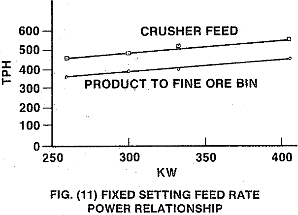
The power drawn by a crusher can be changed by varying the feed rate and/or the setting, as shown in Figs. (11) and (12). A small change in setting can bring about a large change in power rate, Fig. (13). Changing feed rate near optimum power draw gives small change to crusher power rate and the reduction ratio remains approximately the same.
The rapid fluctuation in crusher power draw that is normally associated with high power rate operation
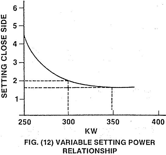
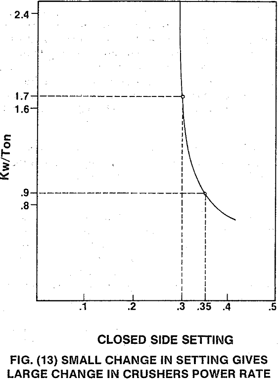
makes it desirable to fit a crusher with an automatic setting control system as shown in Fig. 14 to guard against mechanical overloading. At the same time this maximizes the power rate and average power drawn for a particular configuration.
It has been determined that within a cone crushing chamber, machines using automatic setting regulation can normally operate at more than twice the power rate compared to units operating in a fixed setting mode.
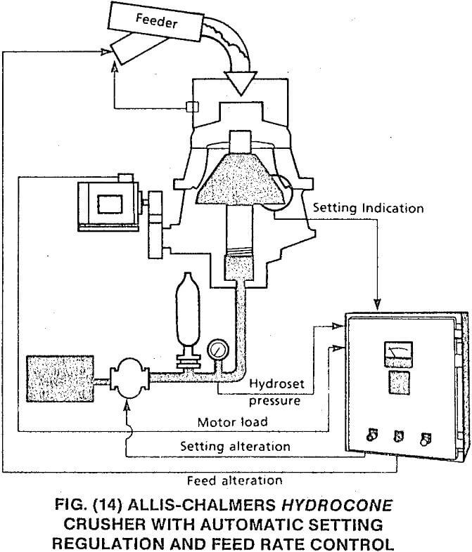
The device in Fig. (14) works by constantly trying to reduce the machine’s setting according to a program, thereby maximizing power drawn within preset limits. If the crusher overloads, it opens up according to another program. Feed rate can be another variable controlled within the same system. The combined setting/feed rate system can be appropriately coordinated to give a crusher power rate control, thus effectively determining reduction ratio as will be seen in more detail following.
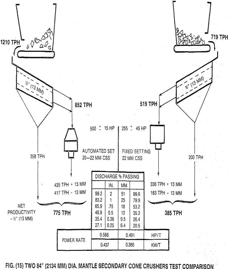
It has been demonstrated that both capacity and quantities of finer sizes produced, Fig. (15), can be improved substantially by using automatic setting controls in a cone crusher.
It can be seen that the yield of minus 13 mm material for the automated set crusher is approximately twice that for the fixed set machine. Also notice that the per cent minus 13 mm and 9.5 mm in the crushers’ discharge is about 10% higher even though the crushers are operating at close to the same close side setting. One of the main reasons for the differential in this test is the larger eccentric throw in the fixed set unit. The smaller eccentric throw and automatically controlled setting increased power draw to give a much higher crushing force. This is analogous to a large pendulum energy in the laboratory tests.
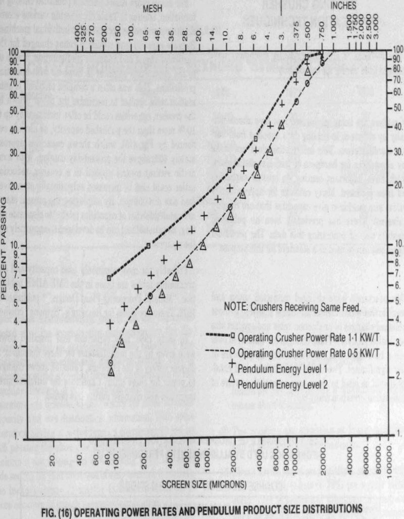
By adjusting both the feed rate and power together, we can change the power rate and, hence, reduction, as is shown from a field test result, Fig. (16). The automated setting and power drawn was almost the same for both operating conditions. The large difference in reduction was due to the different power rates. Superimposed pendulum results again demonstrate the family curve relationships for the laboratory tests.
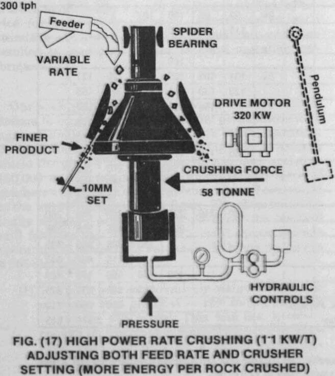
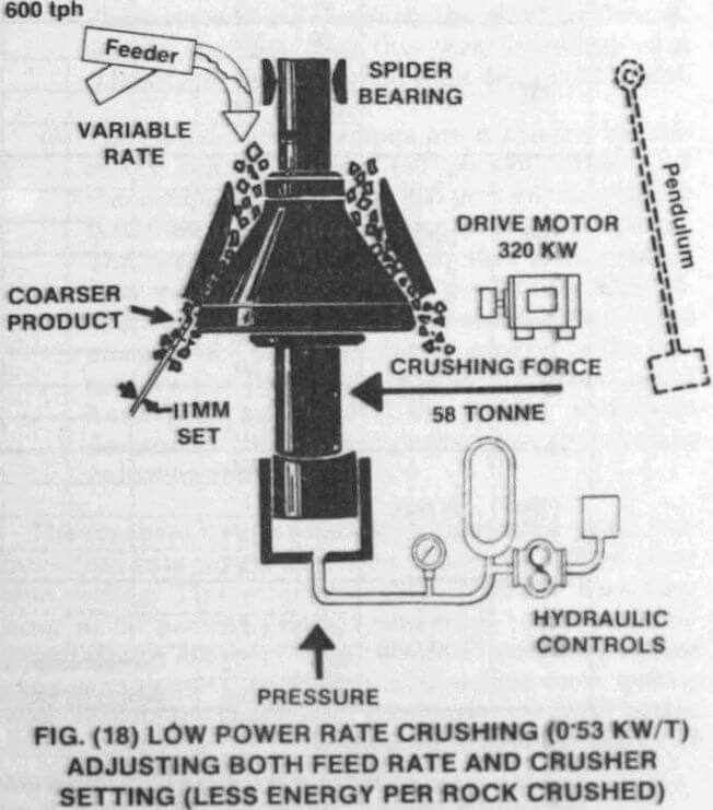
The operating conditions for the crushers are diagramatically shown in Figs. (17) and (18).
It is clearly shown that the same energy applied to more material results in a much coarser product. In these tests the percent minus 12.7 mm (½ inch) changed from approximately 95% to 65% passing when the feed rate was doubled (power rate was effectively reduced by half). The automated setting control adjusted the crusher to the same power draw setpoint (320 KW). Because there is an exponential relationship between power drawn and close side setting, there was only a small 1 mm change between the tests. If an application engineer had been using a catalog, he might have computed the size distribution as 60% passing the setting. Clearly there would be a considerable error if this happened.
Existing Crusher Application Techniques
The methods of applying crushing machinery have changed little during the last century.
Crushers are being engineered into flow sheets normally by reference to catalog data supplied from various manufacturers. This information does not make any allowances for hardness or feed size distribution, which have important bearing on crusher capacities and sizes produced. Many catalogs for approximately similar size machines give capacities that are roughly equivalent. There has previously been no published scientific way of comparing this data. The pendulum impact test can be used as a standard for this purpose.
Manufacturers have changed connected power and eccentric throws on various machines with and without published changes to production rates and product size distribution analyses. These changes have occurred over such a time span that most engineers are unaware of their significance. Two cases of commonly used catalogs should be cited to show how general the nature of published information really is.
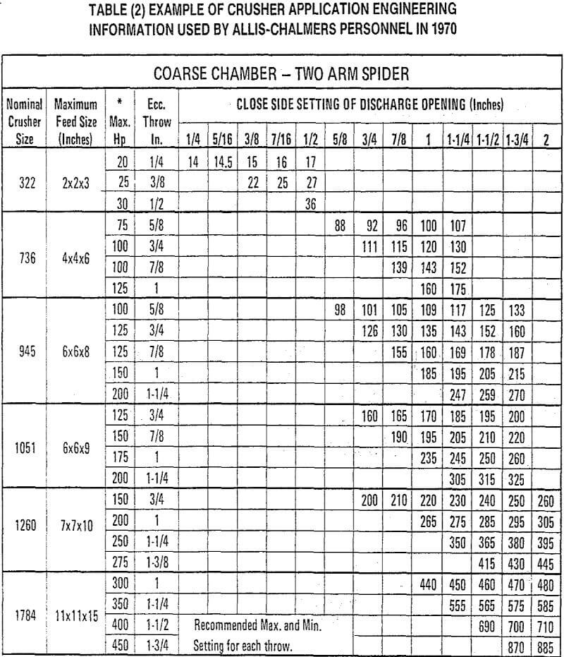
For many years Allis-Chalmers published catalog information, similar to Table (2), showing various eccentric throws and powers connected to individual machines. Because capacity and reduction ratios changed for the particular throw and chamber configuration, it was up to the application engineer to come up with operating predictions. This was often a complex problem. If automation were applied to maximize the power drawn by the crusher, capacities could be often increased by up to 100% more than the published capacity, as already evidenced by Fig. (15), which shows capacities approximately 40% above the present-day catalog. With automatic setting control applied to a crusher, reduction ratios could also be increased substantially on a given feed size distribution. By employing the present standard catalog format of capacities related to close side set¬ting, no rational tool can be developed to accurately size the equipment.
Probably the most commonly used capacity and size graduation tables are those in the SME-AIME publication, “Mineral Processing Plant Design,” published in 1978. These are given for Rexnord’s “Symons” crusher.
In early 1980, new capacities and installed power were given by the manufacturer for these machines. A 25-year survey of the literature, Table (3), shows changes to power for these units. Capacities for different sized machines also changed during this period.
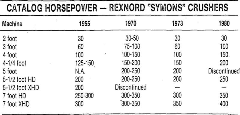
For most manufacturers, nearly all the capacities quoted give the average size distribution for the discharged product as approximately 60% passing a size equivalent to the close side discharge setting. This is regardless of the eccentric throw or physical size of the machine. Because of such complications, designers and operators are referred to the factory for more accurate capacity and size distribution information. With some operators having reported product coarseness as low as 14% passing the close side setting, and with some only making a net average of 40% passing twice the close side setting on vast tonnages of easy-to-crush materials, the inexact nature of catalog information calls for a more accurate approach to crusher application.
Many engineers and some design organizations use standard published catalog capacities and size distributions in computer plant-design programs. Since most crusher manufacturers prefer people to seek factory advice for accurate application, information in such standard computer design programs can and has resulted in significant errors to plant operating performance.
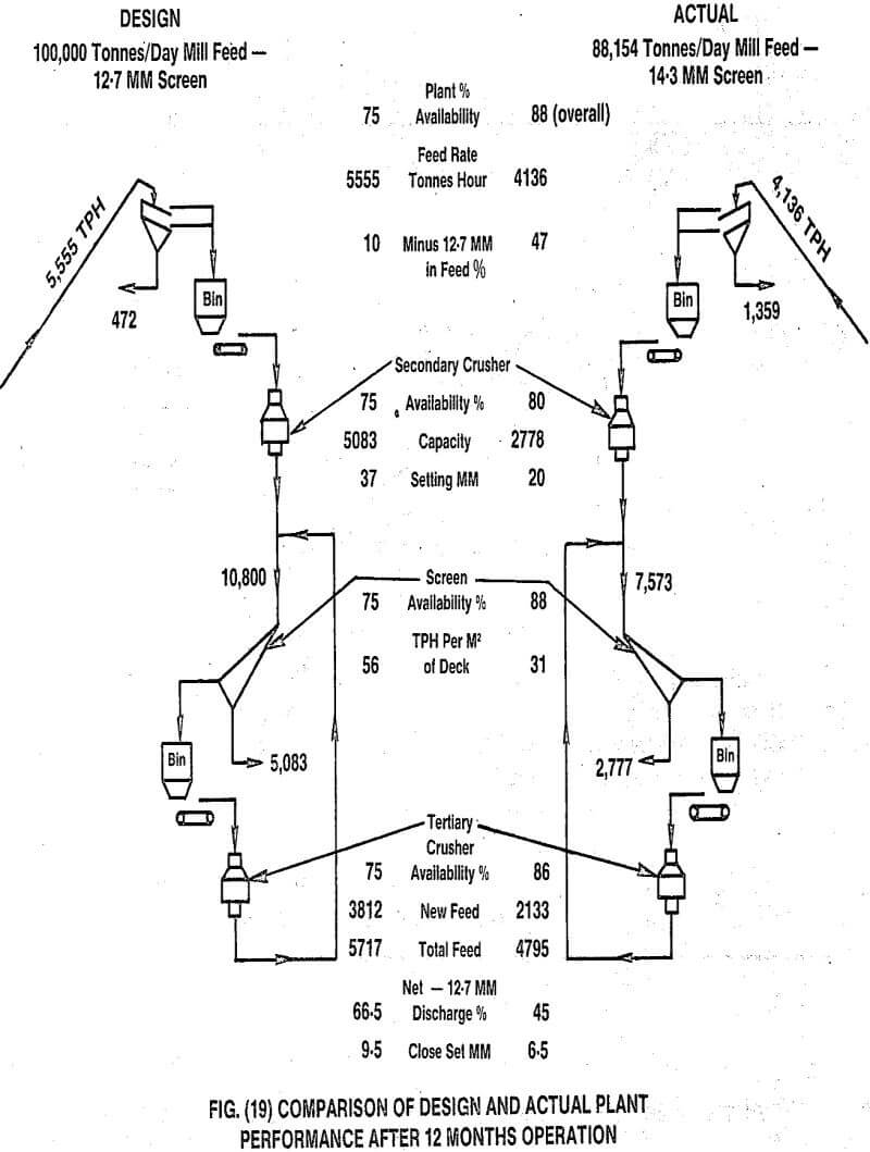
One such plant, which cost several hundred million dollars to construct, compared actual performance data against design after more than one year’s operation. This information is summarized in Fig. (19). In order to shield the plant’s identity, capacity has been scaled to 100,000 tonnes per day. The numbers and sizes of crushers and screens are not given but have been scaled to the 100,000-tonnes-per-day figure. The plant was originally designed assuming it could make the required mil! feed through 12.7 mm (½ inch) square screens operating 75 percent of total time or 18 hours per day in a 365-day year.
- The plant was conservatively designed assuming a coarser feed material — 10% minus 12.7 mm versus the 47% actual. This was not, however, enough for the plant to make the design tonnage even when operating for a longer availability period. If the fines had been in the design proportion, plant output would have only been approximately:
24 x 2778/0.9 x 0.88 = 65,200
tonnes per day at 88 percent availability or 34,800 tonnes short of design. - The crushers are operating at lower capacities and at smaller settings than design.
- Closed-circuit screen productivity is approximately half design (31 versus 56 TPH per square meter deck). This is because of a buildup in near size particles just above the screen aperture dimension.
- The availability of the operating plant increases progressively from 80 percent for the secondary crushers to 88 percent for the tertiary screens. These screens are obviously the plant bottleneck, despite the fact that they are operating at a coarser aperture (14.3 mm) than design (12.7 mm).
- The closed-circuit crushers are making a considerably coarser product (45 percent minus 12.7 mm compared to design, 66.5 percent) despite the fact that they are operating at 6.5 mm setting. The reader should remember that most catalog data would give a standard product for this setting as 60 percent passing 6.5 mm and 95 percent passing 12.7 mm. This coarse product is the reason for the bottleneck in this plant and could have been predicted if the facility had been designed using crusher power rates to calculate reduction ratios.
The crushers in this plant were automated using variable feed rate to control power drawn at a fixed close side setting. First-stage reduction crushers were running at 60 percent average connected power and the closed-circuit crushers were run at 95 percent average connected power. The equipment therefore was running near maximum capability. Obviously we need better design methods for crushing and screening plants if such errors are not to be repeated.
New Design Methods
By using automatic setting and feed rate controls on a crusher to maximize power drawn and optimize the power rate at each stage, significant improvements can be incorporated into any crushing circuit design.
In a recent paper we described a method of designing a crushing plant using power drawn and power rate to define reduction ratios in each stage of crushing. The plant power and power rates were computed from a Bond calculation as applied to the crushing plant feed and output sizes. A comparison of the low and high energy configurations is shown in Fig. (20). Obviously the automated plant in Case B will cost much less to construct than Case A, so automation is an economic necessity.
We would design this plant differently today using energy parameters from the pendulum impact tests for calculations. It would only be necessary to use the Bond feed and product size calculation if no pendulum results were available.

Cone Crushers
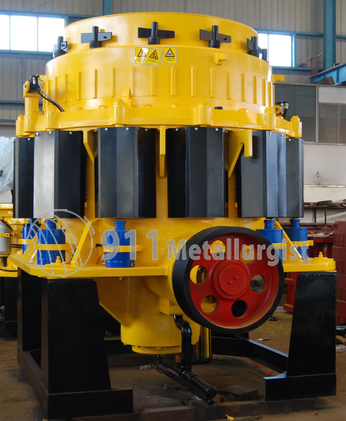
The cone crusher was designed primarily with a view to achieving top performance in the field of fine-reduction crushing. It has also been adapted to what is designated simply as “fine crushing,” which extends into a range below that ordinarily defined by the term “fine-reduction.”
Although the eccentric speeds of the various sizes of this type are not quite so high as the speeds used for the Newhouse crusher, the Hydro-cone crusher definitely rates as a high-speed machine, its product comparing quite closely to that of the former type, for equal close-side settings. Probably the outstanding feature of the. Hydrocone crusher is the hydraulic support, from which its name is derived and which is clearly shown in the sectional view. This device makes it possible to adjust the crusher to any desired setting within its range in a matter of seconds; adjustments may be made while the crusher is running, although the feed must be shut off before operating the adjusting pump. An accumulator in the hydraulic system provides protection against tramp iron or packing.
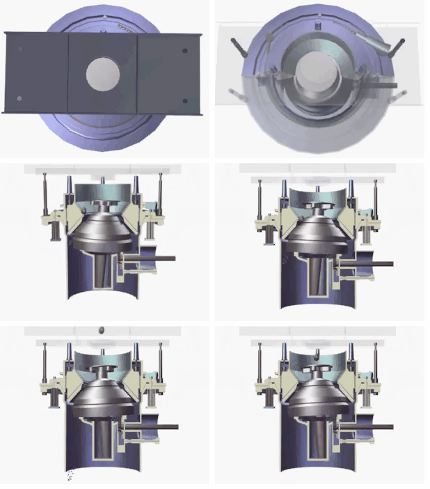
Cone crushers are used in AG and SAG grinding circuits to increase tonnage by effectively dealing with any pebble (critical size) build-up problem. Normally, heavy-duty short-head crushers are employed to crush pebbles. Power and crusher cavity level are the key variables for monitoring and controlling the crusher operation. Crusher product size is adjusted by changing the closed side setting.
On the left is a diagram of the Hydro-cone crushing chamber. A comparison of this chamber with those previously discussed is interesting. It will be noted that the choke-point has been raised far above the discharge level, in fact, to a point not far below the nip-point for the recommended maximum one-way feed dimension. By virtue of the decided flare of the head, and the corresponding flare of the top shell bore, the line-of-mean-diameters slopes sharply away from the crusher centerline. For some, distance above the discharge point the angle between head and concave is very acute; in fact, at the open-side position of the head, this zone is almost parallel.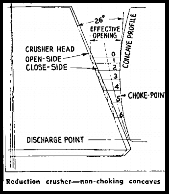
For recommended operating conditions, i.e., for safe combinations of throw and setting, and with screened feed, this type of crushing chamber does not approach anything like a choke or near-choke condition. For the combination shown in the diagram the ratio of volume reduction is almost 1:1 from zone 0-1 to zone 2-3 at the choke-point; consequently, if the crusher is given a screened feed (as all fine-reduction crushers should be) the reduction in voids by the time the choke-point is reached cannot very well reach serious proportions. The diagram shows the standard chamber. With screened feed, these crushers will operate at closed-side discharge settings equal to the throw of the head at the discharge point (usually spoken of as “eccentric-throw.”)
The level in the crusher feed pocket is an important variable since it can indicate whether the feed is building up. A build-up could lead to a plugin the feed chute, a spill through the skirting on the crusher feed, or a crusher plug. None of these are desirable.
In a normal feed situation, the level in the crusher cavity is kept fairly low, just enough to ensure that there is sufficient feed to keep the crusher working, but if the feed has to be suspended suddenly because of impending plugging, the crush-out won’t take too long (10 seconds or less). Normal feed is usually used in standard crushers where the feed particle size is quite large, say greater than 65 mm.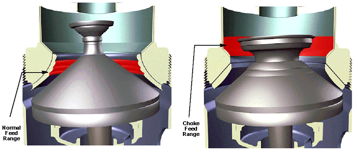
Choke feed is when the crusher cavity is kept full, without spilling out through the skirting. Choke feeding is usually used in short-head crushers where the feed particle is smaller than that for a standard crusher.
Medium and Fine Crushing Chamber
This crusher is a modification of the standard machine, developed for fine-crushing duty. Mechanically, the machine is the same in every respect as the standard crusher of the same type, but for each developed size of machine a special top shell and the concave ring has been designed, with reduced receiving opening, reduced angularity between head and concave, and, consequently, superior characteristics at the finer settings. Medium crushing chambers may be operated at close-side settings of one-half the eccentric-throw, on screened feed; hence capacities at the finer settings are better than those of the standard type. Fine crushing chambers operate at one-fourth the eccentric throw. Inasmuch as the maximum feed size is smaller in the case of the fine chamber, the ratios of reduction are approximately the same for both machines.
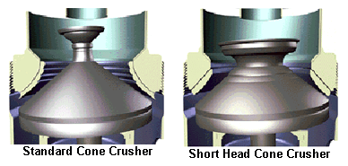
There are two main types of cone crushers: standard and shorthead. They differ by the shape of the cavity. The standard crusher cavity is wider to accommodate larger feed-size material. The short head crusher is designed to crush finer material and to produce a finer product.
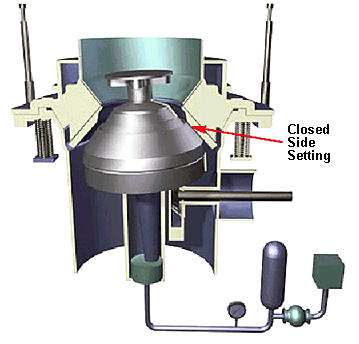
The closest approach between the mantle and the bowl liner is called the closed side setting. This is usually specified by the metallurgist to give the desired crusher product discharge size. It can be checked by running the crusher empty, hanging a lead plug into the crusher bowl, and then removing it to measure the “gap”. The gap is adjusted by rotating the bowl. Some crushers are equipped with a hydraulic jack mechanism on the crushing head assembly instead of having a bowl adjustment ring. The head can be raised or lowered to meet the operator’s needs. It can be very helpful in operation and process control.
Cone Crushers
The Symons Cone Crusher has come into almost universal use during the last few years for the final stage of crushing. It is a development of the secondary gyratory crusher, which is merely a small gyratory crusher designed to break the product of the primary machine down to about 1½-in. size; but the main shaft of a cone crusher instead of being suspended from a spider is supported on a large socket bearing situated immediately under the crushing head and protected from grit and dust by a sealing assembly, this bearing taking the whole of the crushing load.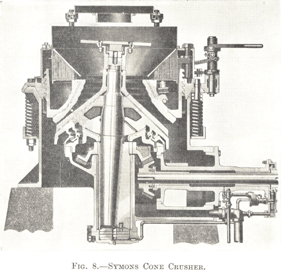
Fig. 8 gives a sectional view of the machine. The main shaft is carried in a long gear-driven eccentric, the rotation of which causes the gyration of the head in the usual way, but the center of gyration is at the apex of the crushing head instead of in the spider. At the top of the bowl, therefore, the lumps of ore entering the crushing zone are cracked by short powerful strokes; but at the bottom the head has a much longer but less powerful stroke, enabling the ore in the finishing stages to be rapidly crushed and quickly discharged without any tendency to choke, a condition which reduces over crushing to a minimum. This, together with the curved shape of the bowl, accounts for the large reduction ratio possible with this type of machine and makes it superior to other secondary crushers and coarse rolls.
It will be seen that the head and the bowl are parallel at the lower part of the crushing zone. The parallel space is deep enough, in conjunction with the speed of gyration, to ensure that no piece of ore can pass through it without being struck two or three times by the head before it falls clear. It follows that, unlike the jaw and gyratory crushers, the size of the product is determined by the distance apart of the bottom edges of the head and bowl in the position when they are closest together.
Coarse buttress threads on the outer circumference of the bowl fit into corresponding threads on the inner side of the adjusting ring, which is held down to the mainframe by a circle of long heavy springs, flexible enough to allow the whole assembly to rise should “ tramp ” iron or other uncrushable material enters the crushing zone. By means of a windlass and chain, the bowl can be rotated in the threads that support it in the adjusting ring while the machine is running, thus enabling the bowl liner to be adjusted for wear or the size of the product to be changed without stopping. The cone crusher is usually set to give a 3/8-in. or ½-in. product when discharging to ball mills.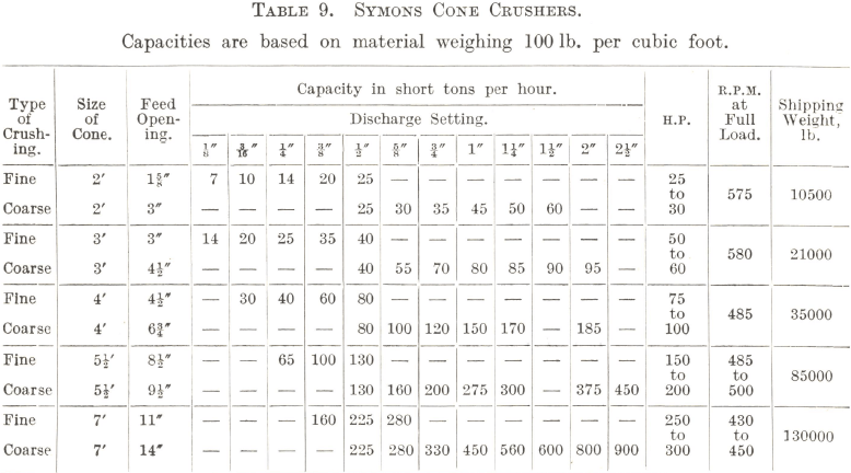
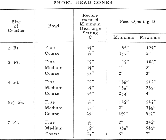
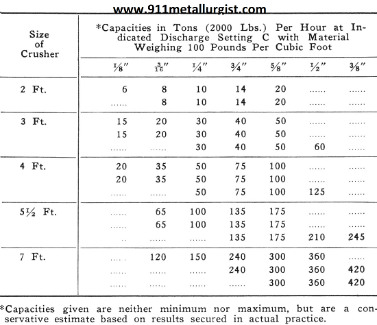
Table 9 gives particulars of the different sizes of crushers. The capacity figures are based on material weighing 100 lb. per cubic foot and must be increased in direct proportions for heavier ores. It will be noted that each size of machine has two ranges of capacity; this is due to the fact that it can be fitted with a coarse or a fine crushing bowl according to the duty that is required of it. With either one, the range of reduction is greater than is economically possible with any other type of dry crushing machine.
A possible disadvantage of the cone crusher is that as a rule it cannot be choke-fed, but must be given an even feed of ore if it is to do efficient work. Should circumstances call for the installation of a machine that can be run if necessary with the ore piled up over the top of the head, a secondary gyratory crusher of the suspended shaft type will be required. The Traylor Reduction Crusher Type TZ, which is constructed on the principles of an ordinary gyratory crusher, but is fitted with a curved bowl liner similar to that of the Symons Cone Crusher, is designed to meet the case. Although the suspension of the shaft restricts the movement of the head to a smaller circle of gyration than that of the cone crusher, the ratio of reduction is still large enough to enable it to crush the product of the primary breaker to ½-in. size (¾-in. for the large machines), and it fulfills the condition that it can be choke-fed. Owing to the smaller movement of the head, however, the capacity for a given range is much less than that of the equivalent size of cone crusher, and the latter is therefore preferred when choke-feeding can be avoided.
Symons Cone Crusher
The Symons Shorthead Cone Crusher, which is constructed on the same general principles as the larger machine, is designed to follow the latter, taking its product at 1-in. and reducing it to about ¼-in. size. The strains imposed on the crushing members, however, would be very heavy if the machine were run with the discharge opening set to ¼-in. or less. It is usual, therefore, to crush in closed circuit with a screen, the discharge opening of the bowl being set to 5/8 or ½ in. Thus a circulating load is built up and a certain amount of choke-crushing takes place, but the method actually gives greater efficiency with a finer product than can be obtained in an open circuit, whatever the discharge setting of the bowl in the latter case.
In ordinary crushing practice, the grinding section is supplied with ½-in. or 3/8-in. material direct from Symons Cone Crushers. But the demand is for a finer feed and it seems likely that the Shorthead Cone Crusher will satisfy this demand to the exclusion of fine crushing rolls.
Symons Cone Crushers have been used extensively for secondary crushing in metallic, non-metallic, rock products, and industrial operations. The Symons Cone was developed to give large capacity, fine crushing. The combination of high speed and wide travel of the cone results in a series of rapid, hammer-like blows on the material as it passes through the crushing cavity and permits the free flow of material through the cavity.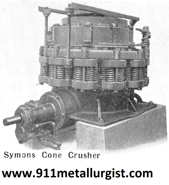
Reduction in size of any particle, with each impact of the head, is regulated by the opening between the head and bowl at that point. A threaded arrangement of the bowl affords a quick and easy method for changing the size of the product or to compensate for wear. This adjustment can be made while the crusher is operating. A parallel zone between the lower portion of the crushing members assures uniform sizing.
Frame, adjustment ring, and cone are made of cast steel; gears are made of specially treated steel and have cut teeth; all bearings are bronze; mantle and bowl liners are manganese steel. The head and shaft can be removed as a unit, and other parts such as the eccentric and thrust bearings can easily be lifted out after the head is removed. The countershaft assembly can also be removed as a complete unit.
The circle of heavy coil springs, which holds the bowl and adjustment ring down firmly onto the frame, provides automatic protection against damage due to tramp iron. These springs compress, allowing the bowl to rise the full movement of the head until non-crushable material passes through. The springs then automatically return to their normal position.
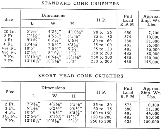
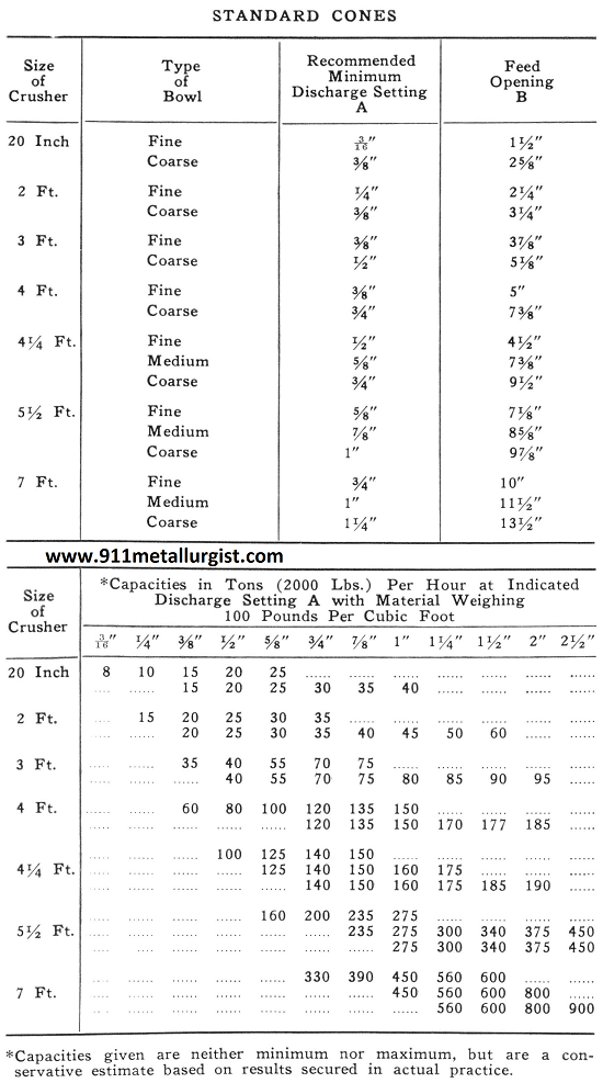
Symons Cone Crushers are made in Standard and Short Head types. They are of the same general construction but differ in the shape of the crushing cavity. The Standard cone is used for intermediate crushing. The Short Head cone is used for finer crushing. It has a steeper angle of the head, a shorter crushing cavity, and greater movement of the head at the top of the crushing cavity.
Standard Cone Crusher Capacity
Short Head Cone Crusher Capacity
Cone Crusher Components and Operating Principle
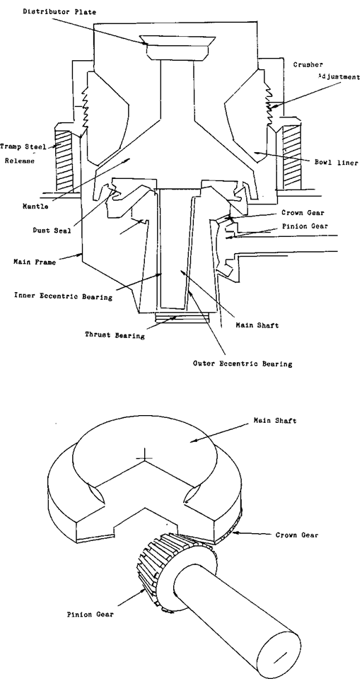 The main components of cone crushers are:
- BOWL LINER
- MANTLE
- PINION and CROWN GEAR
- ECCENTRIC INNER and OUTER BEARING
- THRUST BEARING
- MAINFRAME
- TRAMP STEEL RELEASE
- DISTRIBUTOR PLATE
- MAIN SHAFT
- OIL SYSTEM
- DUST SEAL
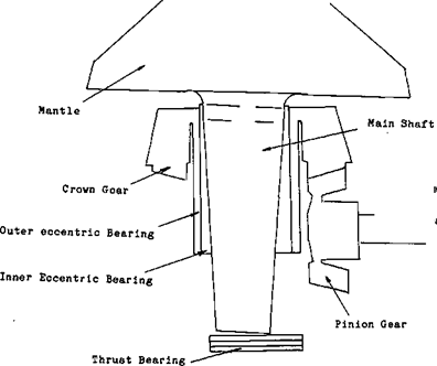
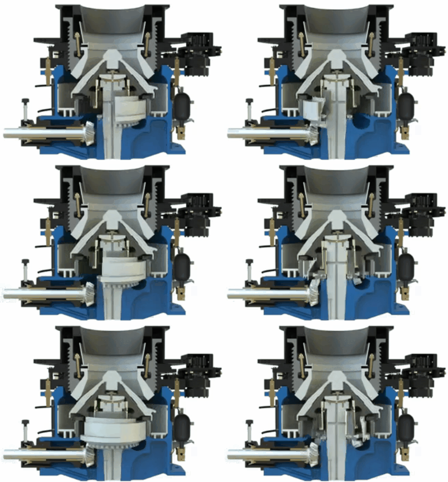
The description of the Operating Principle of cone crushers and how this machine works should begin with the driveline and how the crushing action is generated.
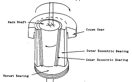
If you observe the illustrations you will notice that the center line of the main shaft is at an angle to the center line of the crusher. The center of the main shaft bisects the center line of the crusher at the opening of the crushing chamber. As the MANTLE revolves that point is the pivot point of the mantle. This means that both the top and the bottom of the crusher mantle have a circular gyrating motion.
 |
 |
TRAMP IRON & CONE CRUSHERS
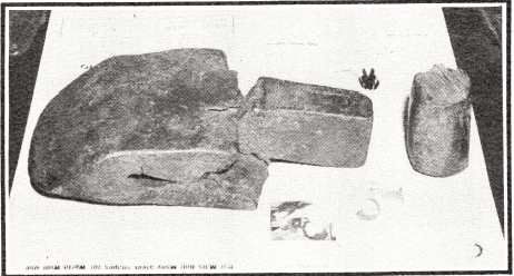 Tramp iron had long been a source of worry to those engaged in fine crushing. Here is what one operator had to say. “Shutdowns were frequent, costs were uncertain because of enforced delays due to excessive breakage. Plugged machines had to be freed continually with a torch to cut out frozen and wedged-in tramp iron. The cone crusher overcame these troubles, helped reduce and stabilize costs.” The best evidence of this statement is the universal acceptance of the cone as the outstanding crusher in its field.
While tramp iron is not recommended as a regular diet for a Cone Crusher, its construction is such that damage will not result should any ordinary noncrushable material get into the crushing cavity. The band of heavy coil springs encircling the frame allows the bowl to lift from its seat with each movement of the head until Such non-crushable object passes off into the discharge. The tramp iron shown in the accompanying illustration passed the protective devices installed for its removal and would have resulted in expensive repairs and long shutdown periods for any crusher except the Symons Cone.
Cone Crusher Short Head VS Standard Head
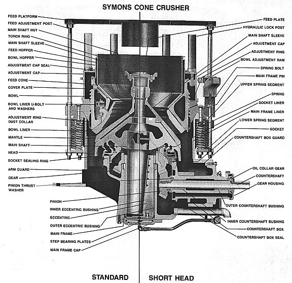
Cone crushers can have two types of ‘heads, standard and short head types. The principle difference between the two is in the shape (size and volume) of the crushing cavities and feed plate arrangements. Standard head cone crushers have cavities that are designed to take a primary crushed feed ranging up to 300mm generating product sizes around 20mm to 40mm. For finer products, short head cone crushers are normally used. They have a steeper angle of the head and a more parallel crushing cavity than the standard machines. Due to the more compact chamber volume and shorter working crushing length, the much needed higher crushing forces/power can be imparted to the smaller-sized material being fed to the crusher. Cavities for the short head machine are designed to produce a crushed product ranging from 5mm to 20mm in a closed circuit.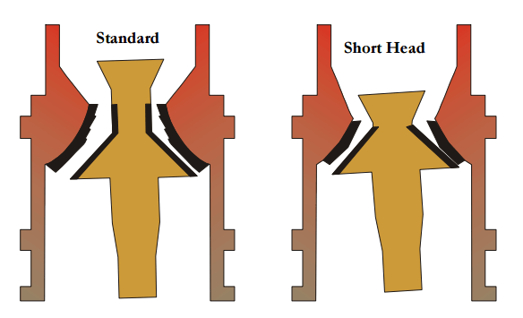
At the discharge end of the cone crusher is a parallel crushing section, where all material passing through must receive at least one impact. This ensures that all particles, which pass through the cone crusher, will have a maximum size, in at least one dimension, no larger than the ‘set’ of the crusher. For this reason, the set of a cone crusher can be specified as the minimum discharge opening, being commonly known as the “closed side setting” (CSS).
Cone Crushers for Sale
Here are facts about the cone crusher known as Hydrocone. This line of hydraulically adjusted gyratory crushers was developed in smaller sizes some fifteen years ago by Allis-Chalmers to meet a demand for improved secondary or tertiary crushing units. The line is now expanded to include sizes up to 84-in. diameter cones.
This modern crusher is the result of many years of experience in building all types of crushing equipment, when the first gyratory or cone crusher, the Gates, was put into operation. Overall these years AC has followed a continuing policy of improvement in crusher engineering, changes in design being based on operating experience of crushers in actual operation.
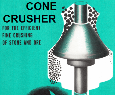
The Hydrocone cone crusher is the logical outgrowth, a crusher having a means of rapidly changing product size or compensating for wear on the crushing surfaces a crusher which produces a better, more cubical product than any comparable crusher and a crusher so designed that it can be operated and maintained with a minimum of expense.
Cone Crusher Hydraulic System Operation
The most important fact about the Hydrocone crusher is its hydraulic principle of operation. Hydraulic control makes possible quick, accurate product size adjustments fast unloading of the crushing chamber in case of power failure or other emergency protection against tramp iron or other uncrushable materials in the crushing chamber.
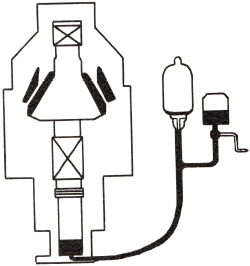
Another important fact about this crusher is its simplicity of design and operation.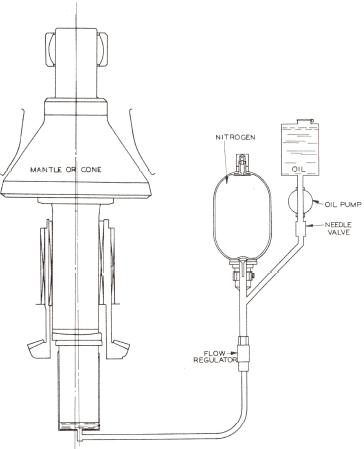 The accompanying sketch shows the simplicity of the Hydrocone crusher’s principle of operation. The main shaft assembly, including the crushing cone, is supported on a hydraulic jack. When oil is pumped into or out of the jack the mainshaft assembly is raised or lowered, changing the crusher setting.
The downward thrust of the main shaft assembly, as well as its gyrating and rotating motion, is carried on a highly efficient step bearing.
Gyratory motion is imparted to the crushing head by means of an eccentric at the lower end of the main shaft. The eccentric is rotated by means of a bevel gear and pinion from the countershaft.
Fast & Easy Control Product Size
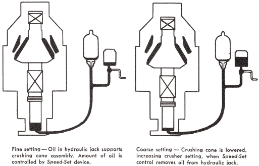
Since the crushing cone is supported on a hydraulic jack, its position with respect to the concave ring, and therefore the crusher setting, can be controlled by the amount of oil in the hydraulic jack.
Speed-Set control raises or lowers the crushing shaft assembly hydraulically, and permits quick adjustment to produce precise product specifications without stopping the crusher. Speed-Set control also provides a convenient way to compensate for wear on crushing surfaces.
On Hydrocone crushers in sizes up to 48-in., the Speed-Set device is a hand-driven gear pump; on the larger sizes a motor-driven gear pump operated by push-button. On all sizes the setting can be changed in a matter of minutes by one man without additional equipment, reducing downtime materially.
Protect Cone Crusher from Tramp Iron
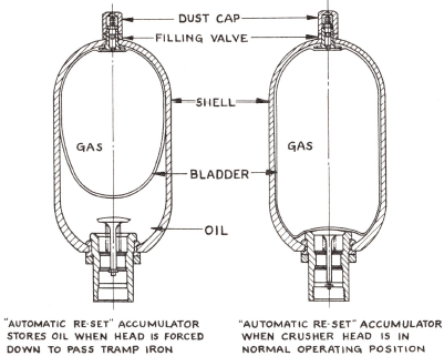
Protection against tramp iron or other uncrushable materials is afforded by an accumulator in the hydraulic system. This consists of a neoprene rubber oil-resistant bladder inside a steel shell. This bladder is inflated with nitrogen to a predetermined pressure higher than the average pressures encountered during normal crushing.
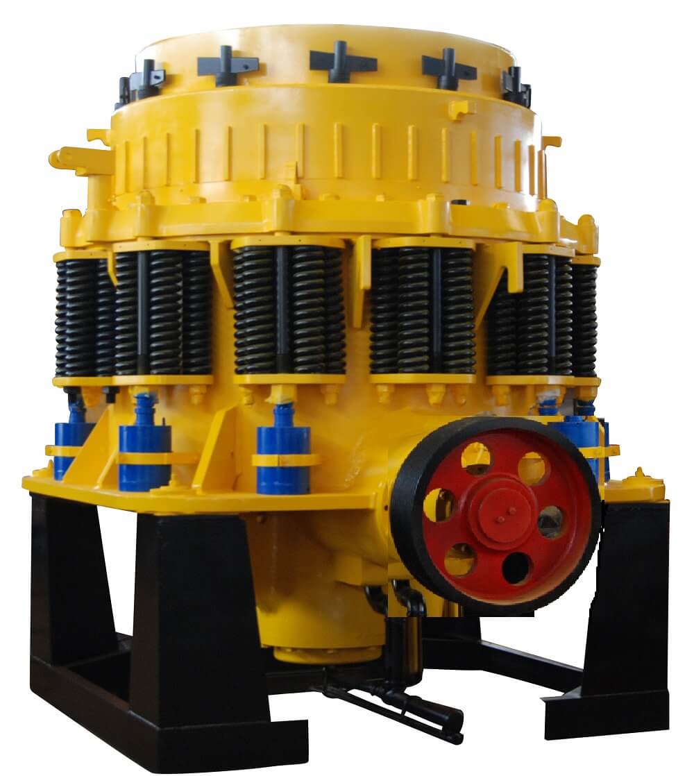
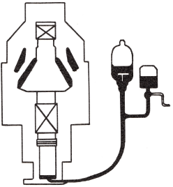
Ordinarily, the Automatic Reset remains inoperative, but if steel or some other foreign material should enter the crushing chamber, the oil pressure in the hydraulic jack will exceed the gas pressure in the accumulator. The bladder will then compress, allowing the oil to enter the steel shell. This permits the crushing cone to lower and discharge the uncrushable material without damage to the crusher.
After the crushing chamber is freed of the foreign material, the gas pressure in the accumulator will again exceed the oil pressure in the hydraulic system. Oil is then expelled from the accumulator shell and the crushing cone is returned to its original operating setting automatically.
The Automatic Reset returns the crushing head to its position quietly, rapidly and without shock. It also protects the crusher against packing and power surges.
 |
 |
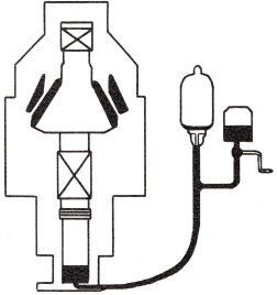 |
| In normal operation, oil in the hydraulic jack maintains the position of the crushing cone with respect to the concave ring. Gas pressure in the accumulator exceeds oil pressure in the hydraulic jack. | When tramp Iron enters the crushing chamber, pressure on oil in the hydraulic jack becomes greater than the gas pressure in the accumulator. This forces oil from the hydraulic system to the accumulator, allowing the crushing cone to lower until tramp iron is discharged. | After tramp iron has been passed, gas pressure forces oil back to hydraulic jack. The crushing cone returns to original setting because same amount of oil is returned. |
 |
 |
| Left: Bladder inside accumulator shell contracts, allowing oil from hydraulic jack to enter shell when crushing head is forced down to pass tramp iron. Right: Accumulator during normal operation. | Automatic Reset passed this manganese steel dipper tooth through a 1260 Hydrocone crusher in an iron ore operation. Dipper tooth measures approximately 12 x 7 x 2 inches. Crusher also passed steel chunk shown. |
A Hydrocone crusher will produce a cubical product with excellent size distribution and a minimum of flats and slivers. This is especially important in the crushed stone industry where a cubical stone is required to meet rigid product specifications. It is also of considerable significance in the mining industry where the elimination of large amounts of tramp oversize reduces circulating loads or makes open circuit crushing possible.
The reason why the Hydrocone crusher will produce such a uniform, cubical product is that it has a small eccentric throw with respect to the crusher setting. This means a smaller effective ratio of reduction during each crushing stroke, and therefore, the production of fewer fines and slivers. Likewise, a small eccentric throw means a small open side setting, which results in a smaller top size of the product. A large percentage of the product from a Hydrocone crusher will be of a size equal to or finer than the close side setting.
 Cone Crusher Feed Distribution
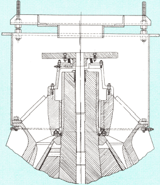
For fine crushing, or in installations where the feed to the crusher is irregular, the use of a wobble plate feeder is recommended. This feeder is installed in place of the spider cap and affords a means of controlling the feed to the crusher, as well as a means of distributing the feed evenly around the crushing chamber.
Essentially, the feeder consists of a plate that is oscillated by a shaft extending down into the crusher’s main shaft. The motion of the main shaft oscillates or “wobbles” the feeder plate. The plate is supported on a rubber mounting which permits its motion and, at the same time, positively seals the top of the spider bearing against the entry of dust. Maintenance is reduced by the use of self-lubricating bushings between the feeder plate shaft and the crusher main shaft.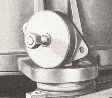
Crusher Foundation
Hydrocone crushers are mounted on rubber machinery mountings in order to reduce installation costs and make it possible to locate these machines on the upper floors of crushing plants. These mountings operate without maintenance, absorb the gyrating motion of the crusher, thereby eliminating the need for massive foundations. Rubber mountings also prolong the life of the eccentric bearing, since this bearing is not subjected to the severe pounding encountered when rigid mountings are used.
Uniform Crusher Discharge Product

Cone Crusher Dust Seal Protects From Wear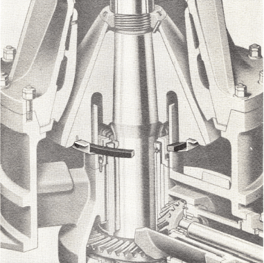
The exclusion of dust and dirt from the internal mechanism of the crusher is of extreme importance from a maintenance standpoint. To accomplish this, Hydrocone crushers are equipped with one of the most effective dust seals yet devised.
This seal consists of a self-lubricating, graphite impregnated plastic ring which is supported from the head center in such a way that it is free to rotate, or gyrate, independently of the head center.
The plastic ring surrounds the dust collar with only a very slight clearance between the two parts. With the plastic ring being free to move as it is, it accommodates the rotation, gyration, and vertical movement of the main shaft assembly, maintaining the seal around the dust collar at all times. Because of its lightweight and self-lubricating characteristics, wear on the plastic ring is negligible.
Fast Crusher Maintenance Reduces Downtime
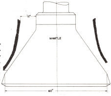
The ease with which any wearing part can be replaced is of the utmost importance to any crusher operator. With this in mind, the Hydrocone crusher has been designed so that any part can be replaced by disturbing only a minimum number of other parts.
For example, the Mantalloy crushing surfaces are exposed by simply removing the top shell from the crusher. This can be done easily by removing the nuts from the studs at the top and bottom shell joint. The eccentric and hydraulic support mechanisms are serviced from underneath the crusher without disturbing any of the feeding arrangements, or the upper part of the crusher.
In all phases of its design, the Hydrocone crusher has been built so that it can be serviced and put back into operation with a minimum of downtime and maintenance expense.
CONE CRUSHER LUBRICATION SYSTEM
Efficient lubrication of all wearing parts is one of the reasons why crushing costs are low with the Hydrocone crusher. On most sizes, lubrication is divided into three distinct systems, each functioning independently.
SPIDER BEARING LUBRICATION
This bearing, whether of the ball and socket type as on the smaller sizes, or of the “hourglass” design (as shown) found on the larger Hydrocone crushers, is pool lubricated. On the 51, 60 and 84-inch sizes, provision is made for introducing the lubricant from outside the top shell through the spider arm. On the smaller crushers, oil is introduced through an oil inlet in the spider cap. On all sizes, oil is retained in the bearing by a garter-type oil seal located in the base of the spider bearing.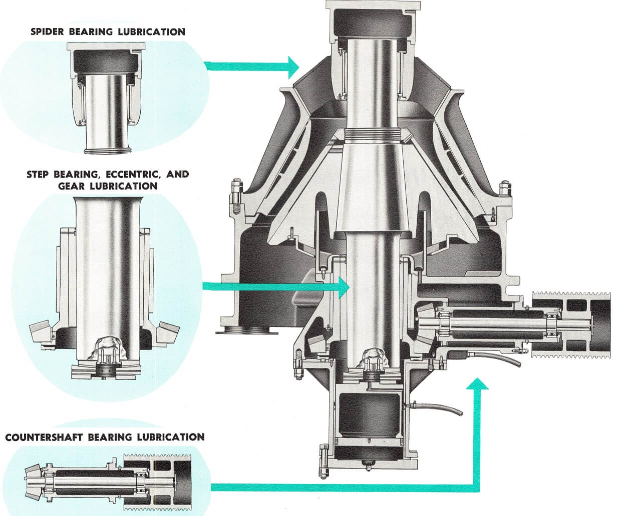
Step Bearing, Eccentric, Gear Lubrication
All Hydrocone crushers are provided with a compact external lubrication system consisting of an oil storage tank, an independently motor-driven oil pump, a pressure-type oil filter, and a condenser-type cooler.
Cool, clean oil is pumped into the crusher from the conditioning tank, lubricating first the three-piece step bearing assembly. The oil then travels up the inner surface of the eccentric, lubricating the eccentric bearing and main shaft.
At the top of the eccentric, the oil is split into two paths. Part of the oil flow passes through ports in the eccentric and down its outer surface, lubricating the bronze bottom shell bushing, driving gears and wearing ring. On the 48-in. and smaller crushers, the balance of the oil overflows the eccentric and returns over the gears to the bottom of the crusher where it flows by gravity back into the conditioning tank. On the 51-in. and larger Hydrocone crushers, any oil which overflows the top of the eccentric is returned directly to the conditioning system without coming into contact with the gears.
The lubrication system includes flow and temperature switches that protect the crusher in the event of oil flow failure or overheating.
COUNTERSHAFT BEARING LUBRICATION
On all but the 36 and 48-in. Hydrocone crushers, the countershaft bearings are of the anti-friction type with separate pool lubrication. Both ends of the countershaft bearing housing are sealed by garter spring-type oil seals to prevent dirt or other contaminants from entering the system.
The 36 and 48-inch crushers have babbitted sleeve type bearings which are lubricated with cooled, clean oil from the external conditioning system.
Cone Crusher Eccentric Design
Rather than use one eccentric throw under all operating conditions, Hydrocone crushers are designed to operate most efficiently with a predetermined ratio of eccentric throw to the crusher setting. By operating with an eccentric throw specifically selected for a given application, the most desirable crushing conditions are attained — the most economical use of Mantalloy crushing surfaces reduced crusher maintenance a more cubical product.
The eccentric throw is controlled by a replaceable bronze sleeve in the cast steel eccentric. This sleeve, being a wearing part, can be renewed readily in the field. Also, should operating conditions change, the throw or motion of the crushing head can be changed accordingly.
Because of the large choice of eccentric throws available — and the variety of crushing chambers that may be obtained — a Hydrocone crusher may be selected that will fulfill the requirements of almost any secondary or tertiary crushing operation.
They may be used in the crushed stone industries to produce a premium cubical product in the mining industries to produce a grinding mill feed having a minimum of oversize, thereby reducing circulating loads and making open circuit crushing possible. The Hydrocone crusher is used in the cement industry to reduce cement clinker prior to finish grinding.
TYPES of CRUSHING CHAMBERS
One of three general types of crushing chambers can be furnished for any size Hydrocone crusher — to suit your specific needs. The selection of the proper chamber for a given application is dependent upon the feed size, the tonnage to be handled and the product desired. A crusher already in use can be readily converted to meet changing requirements, making this machine highly flexible in operation.
COARSE CRUSHING CHAMBER
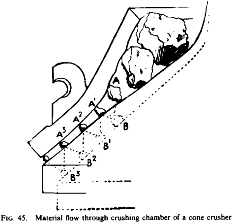 The Coarse crushing chamber affords the maximum feed opening for a given size crusher. Crushers fitted with a Coarse chamber can be choke fed, provided that product size material in the feed is removed.
The Coarse chamber has a relatively short parallel zone and is designed to be operated at a close side setting equal to or greater than the eccentric throw. For example, a crusher with a 3/8-in. the eccentric throw should be operated at a 3/8-in. (or more) close side setting, and therefore a ¾-in. open side setting. Optimum capacity and product will result when operated under these conditions, as well as most economical wear on the mantalloy crushing surfaces.
One way dimension (slot size) of the feed to a crusher fitted with a Coarse chamber should not exceed two-thirds to 70 percent of the feed opening. The maximum feed size to an 848 Hydrocone crusher would therefore be about 5½-in. one way dimension.
The use of a wobble plate feeder, furnished as optional equipment, is recommended if the feed size is relatively large, if the crusher is to be operated in closed circuit, or if the feed to the crusher is irregular.
COARSE CHAMBER PRODUCT
If the Hydrocone crusher is operated with a Coarse crushing chamber, the product will average about 60% passing a square mesh testing sieve equal to the close side setting of the crusher. On certain materials which break very slabby, this percentage will be somewhat lower, and on cubically breaking material the percentage will be somewhat higher. As an average, approximately 90% of the product will pass a square mesh testing sieve corresponding to the open side setting, although this percentage frequently runs higher.
INTERMEDIATE CRUSHING CHAMBER
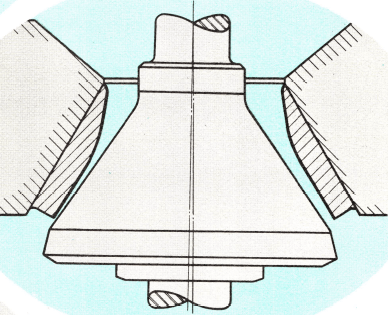 The Intermediate crushing chamber has a feed opening somewhat less than a coarse crushing chamber, but because of its longer parallel zone, is designed to be operated at a close side setting equal to or greater than half the eccentric throw. For example, with a ¾-in. eccentric throw, the minimum close side setting would be 3/8-in.
Crushers fitted with this type of chamber can be choke fed, provided that product size material in the feed be removed ahead of the crusher. The one-way dimension or slot size of the feed to a crusher should not exceed approximately half the receiving opening. A 436 Hydrocone crusher with a 5/8-in. the eccentric throw could be operated at 5/16-in. close side setting and feed size should not exceed 2-in. one-way dimension.
The wobble plate feeder, although not required under most circumstances, is recommended if the feed is irregular, or if the crusher is operated as a re-crusher, at a relatively close setting, or in a closed circuit.
INTERMEDIATE CHAMBER PRODUCT
Because of the longer parallel zone in this crushing chamber, a somewhat greater percentage of the product will pass a square mesh testing sieve equal to the close side setting. This will usually average about 65 to 70%, with this percentage varying, depending on the material being crushed. Very frequently, 100% of the product will pass a square mesh testing sieve equal to the open side setting of the crusher.
FINE CRUSHING CHAMBER
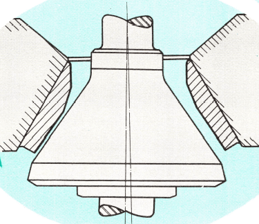 The Fine crushing chamber has the longest parallel zone and therefore the smallest feed opening for any given size crusher. It can be operated at ratios of eccentric throw to close side setting of up to 4 to 1. With a ¾-in. throw, for example, a 236 Hydro-cone crusher could be operated at 3/16-in. on the close side.
Because of their design, crushers with Fine crushing chambers cannot be choke fed but must be equipped with the wobble plate feeder. The maximum one-way dimension of the feed approaches the crusher feed opening. A 348 Hydrocone crusher can be fed with material up to 3-in. one-way dimension.
FINE CHAMBER PRODUCT
The Fine crushing chamber will give the highest percentage passing the close side setting of any of the chambers discussed here. The product will average approximately 75% passing a square mesh testing sieve equal to the close side setting. Because of the long parallel zone, the top size of the product will be only slightly larger than the close side setting of the crusher.
Designs of CONE CRUSHER CHAMBERS
In addition to the three general types of crushing chambers described here, special chambers can be designed to meet varying operating requirements, giving the crusher even greater flexibility than can be obtained with these three main types.
For example, a special concave ring can be used in a 636 Hydro-cone crusher which will reduce the feed opening to 5 inches and permits a two to one ratio of eccentric throw to close side setting. Thus, the crusher can be furnished to fit the exact requirements of any application.
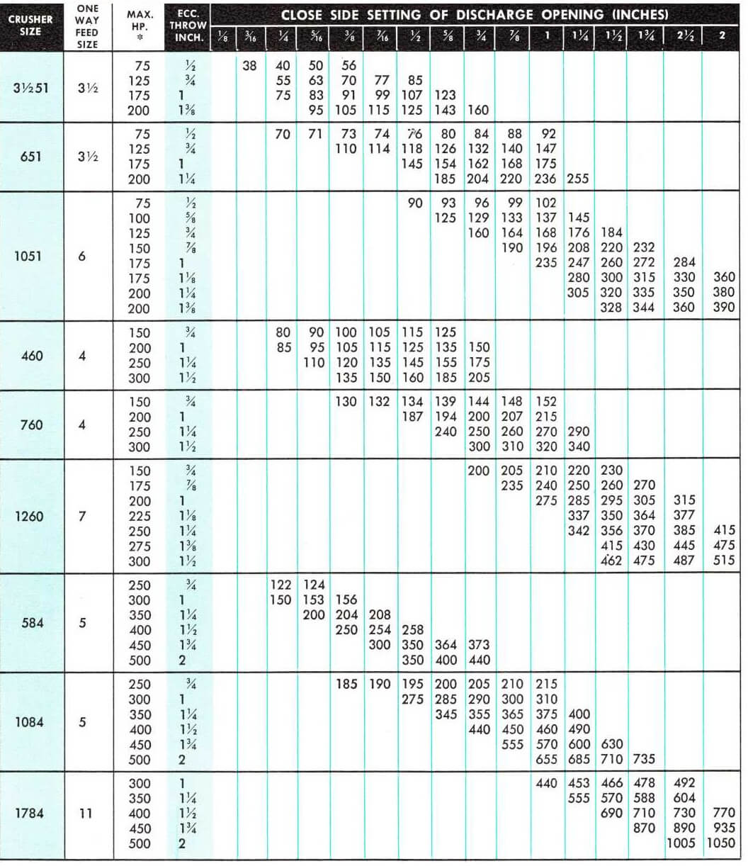
HYDRO-CONE CRUSHER CAPACITIES
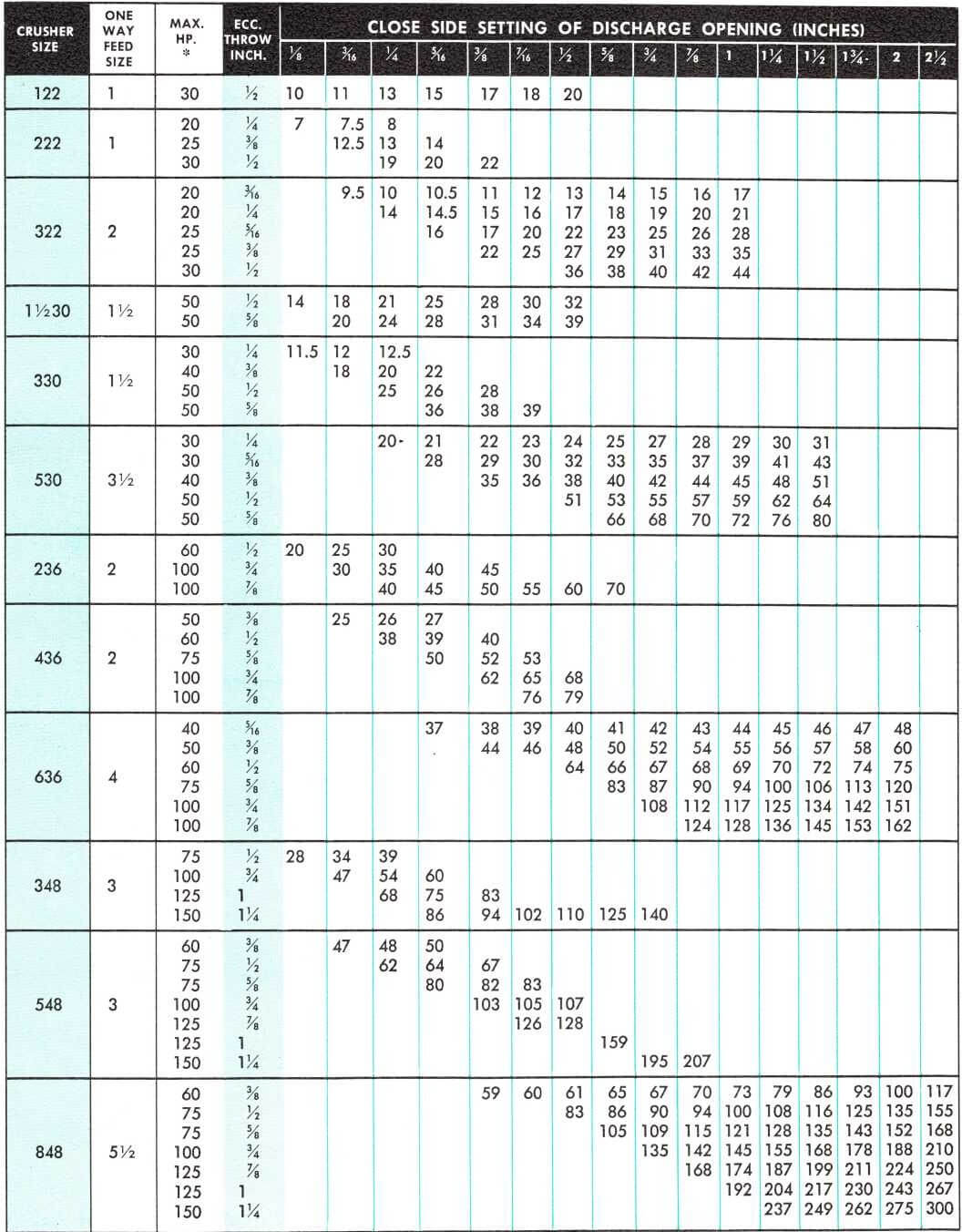
The following capacity table gives a complete range of all Hydrocone cone crusher capacities with varying crushing chambers and eccentric throws. This table shows the minimum recommended setting for any given eccentric throw, the recommended maximum one-way (slot size) dimension of the feed, and the maximum recommended horsepower for any eccentric throw.
Capacities given are based on crushing dry feed from which the product size material has been removed. The material must readily enter the feed opening and be evenly distributed around the crushing chamber. The table is based on material weighing 100 lb per cubic foot crushed. Any variation from this must be accounted for.
Cone Crusher Discharge Screen Analysis SHOWS UNIFORMITY

Crusher Product Screen Analysis
The curves on the following page can be used to approximate the screen analysis of the product from any given Hydrocone crusher. These curves are only approximations since the actual screen analysis of the product of a Hydrocone crusher will depend upon the nature of the material being crushed, the feed size and a number of other considerations which could not be taken into account in these curves. Within these limits, the curves should give fairly accurate estimates.
Note that the Coarse crushing chamber is represented as giving a product of which 60 percent will pass the close side setting, the Intermediate chamber 67½ percent and the Fine chamber 75 percent passing the close side setting. These percentages are the averages of a large number of tests and some variations from these must be expected. If material breaks slabby the percentage with a coarse crushing chamber may be as low as 50 percent; if it breaks very cubically it might be as high as 70 percent, or even higher.
How to use Crusher Product Curves
These curves have been prepared so that they can be used for any crushing chamber. To estimate the product of any Hydrocone crusher, it is necessary to know the type of crushing chamber used (Coarse, Intermediate or Fine), the close side setting and the eccentric throw.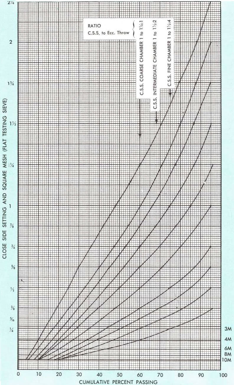
If the crusher is a 636 Hydrocone crusher with a 3/8-in. throw and a 3/8-in. close side setting, the approximate screen analysis would be the curve that would pass through the 3/8-in. horizontal line and the vertical line representing the close side setting for the Coarse crushing chamber, which is the 60 percent passing line. If no curve passes through the precise point of intersection between the horizontal and vertical lines, an approximate curve can be sketched in which parallels the other curves. The same procedure can be used for approximating the products from any other crushing chamber.
| APPROXIMATE WEIGHTS OF MATERIALS, CRUSHED, IN POUNDS PER CUBIC FOOT
Barite………………………………………………..170 |
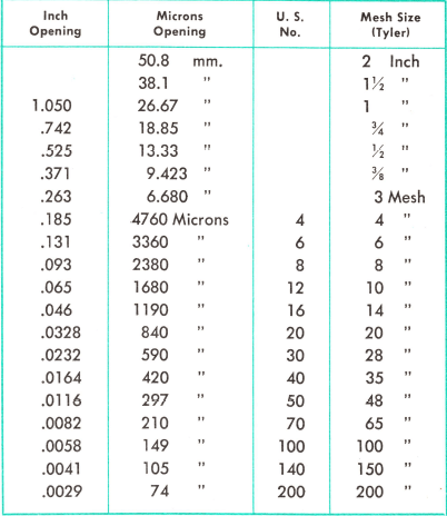
MESH OPENINGS OF SCREENS
|
- How to Select the Correct CONE Crusher
- CONE CRUSHER MOTOR SIZING
- How to Install a Cone Crusher
- Cone Crusher Parts
- Cone Crusher Maintenance
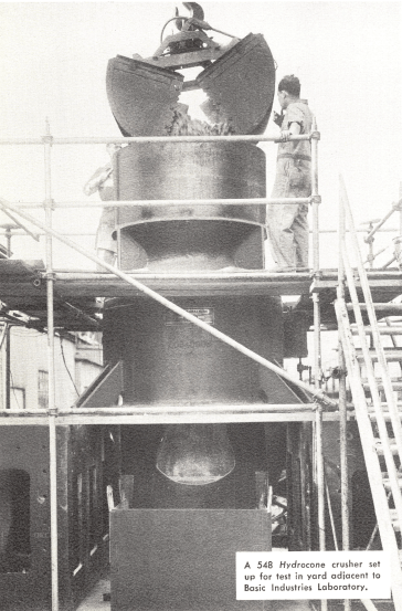
Crushing Test Laboratory & Engineering
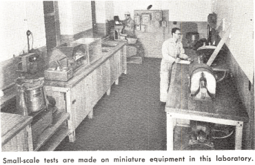
We can provide testing to solve the most difficult crushing problems. Laboratory equipment makes it possible to measure the crushing strengths and characteristics of rock or ore samples accurately, and this data is used in the selection of a crusher of proper size and type.
Impact and batch tests are frequently sufficient to indicate the type and size crusher that will be the most economical for a particular application. However, batch testing is often followed by pilot plant tests to provide additional information about large-scale operations, or to observe rock or ore reduction under actual plant operating conditions.
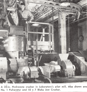
Pilot plant tests duplicate a continuous crushing operation provide a practical demonstration of the commercial potential of the process on a pilot scale. Such tests are useful because they may disclose factors that affect the full-scale operation, favorably or otherwise, but which remain hidden in tests on limited samples.
All Laboratory tests are guided by modern scientific knowledge of crushing fundamentals and by our invaluable backlog of experience in engineering and building all types of crushing equipment — for any crushing application.
In addition to the facilities for crushing tests, the Laboratory maintains complete batch and pilot mill facilities for use in investigating an entire process. Tests in grinding, sizing, concentrating, thickening, filtering, drying, and pyro- processing can be made.
 |
 |
 |

