Figure 1 shows the head-on view of a typical overflow discharge mill including the definition of symbols and specific mill volumes to be used. In this discussion it is assumed that the overflow discharge mill being operated at steady-state will demonstrate a reservoir effect, that is that the Volume 1 of Figure 1 will be fully occupied by the mill contents. Mill contents in this description will include the total volume associated with media, material being ground, and water with no specific regard to the relative amounts of each in any specific volume segment of the mill, e.g. Volume 1. As long as the slurry being ground is not too viscous [e.g. does not have a yield value], direct visual observation of operating industrial scale overflow discharge mills indicates that the reservoir concept is reasonably valid. Using simple geometry concepts, it can be shown that the mill reservoir volume can be expressed as:

It has been suggested with rather dilute slurries, that the right-hand portion of Volume 1 may actually be mostly water through which fine particles can be transported. It is well recognized that in a rotating mill, some fraction of the mill contents is lifted above the level of the bottom of the discharge. The terms cascading and cataracting are often used qualitatively to describe industrial scale operating mills. It is difficult to quantitatively determine the height and shape of this lifting action as well as the composition of water and solids associated. Again, based on direct visual observations of operating industrial scale mills, the shape of this lifted mill content volume, e.g. Volume 2 and Volume 3 of Figure 1, appears to vary along mill length and is somewhat changeable with changing slurry density, mill rotational speed, solids feed rate, etc. Yet as noted in the introduction, it also appears to a first approximation that the average industrial scale mill contents volume at steady-state (Volume 1 + Volume 2 + Volume 3 of Figure 1) is roughly constant regardless of rather large variations in slurry density, solids feed rate, etc.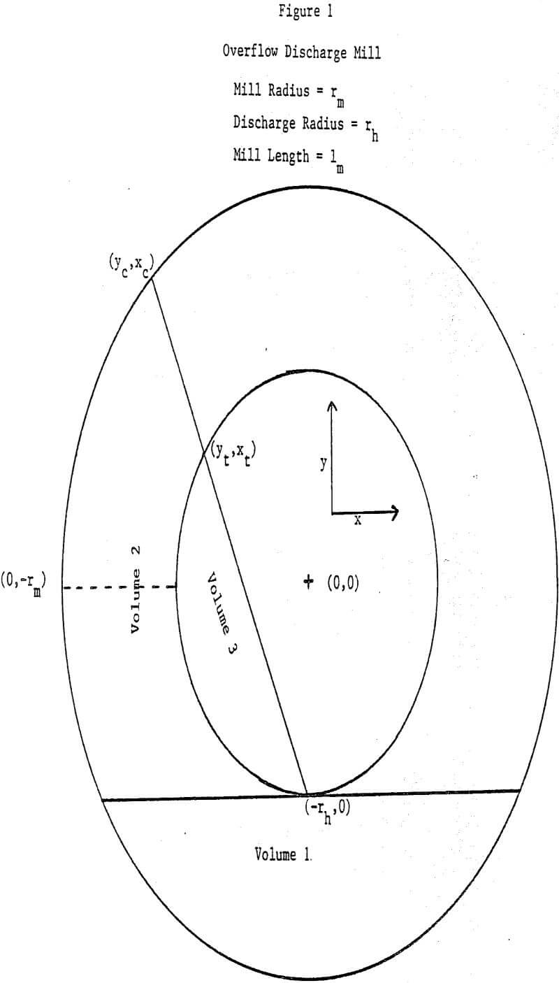
For the sake of simplicity, it is assumed that the profile shape of this lifted mill contents is linear and passes through the bottom point of the discharge opening as indicated in Figure 1. It is then possible to derive general volume formulae for calculating Volume 2 and Volume 3.
Thus:
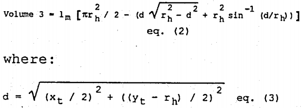
Volume 3 is the volume of mill contents which, at steady state, is flowing out of the mill. The equation of the linear profile line is given by:

Thus it is possible to a priori pick any given Yt value between -rh and +rh, and then calculate the associated xt from:
xt = √r²h – Y²t……………………………………………………………………eq. (6)
which identifies the intersection of the profile line and the discharge opening, (Yt, xt).
The determination of the line of eg. (4) with the outer mill circle can then be done by solving simultaneously eg. (4) and the equation of the outer circle:
x² + y² = r²m…………………………………………………eq. 7
Substituting y from eg. (4) into eg. (7) and applying the standard quadratic formula leads to:

The value of yc following directly from applying eg. (7) with x = xc.
It then follows that:
Volume 2 + Volume 3 =
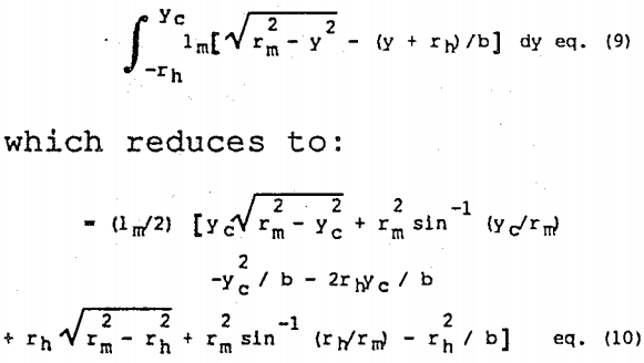
Volume 2, of course, is then calculated from taking eq. (2) away from eq. (10).
A simple Fortran IV program was then written which calculates for a given mill geometry (a given rm, rh, and lm) what the various volumes (1, 2, and 3) of Figure 1 are as yt is systematically increased from -rh to +rh. As is apparent from the figure, increasing the value of yt systematically increases the total mill contents volume.
It is obvious that there are some physical restrictions that come into play on the flow as indicated by Figure 1. If one uses well-known chemical engineering principles of fluid flow, Perry (1963), it is likely that there must be some analogy between fluid flow from a larger diameter pipe (the mill) into an abrupt constricted smaller diameter pipe (the discharge opening). 