When the slurry cannot be transferred from one machine to the next by gravity, one method of handling it is by means of a Wilfley slurry Pump, which is shown in Fig. 21. It is employed in most modern flotation plants for elevating and transferring all classes of material from coarse gritty slurry to fine slime. Differing considerably in design and construction from the usual type of centrifugal pump, it has the advantage that the conventional stuffing-box is replaced by a centrifugal seal which dispenses with the necessity for gland water and eliminates all wear on the shaft. This seal is so constructed that the intake chamber is open to the atmosphere. The pump can therefore have no suction and must be fed by gravity through the feed opening (35) from a box or sump designed to provide an intake head of at least 4 ft.
Slurry Pumps
The pumping chamber consists of a case (1) and follower plate (3). The runner (25) is of the enclosed type with a single inlet located on the side nearer the drive, and is cast in one piece with the expeller ; the combined casting is illustrated separately in Fig. 22. It is a taper fit on the driving shaft (15) and is secured to it by a runner bolt (29). The shaft projects with very small clearance through a circular opening in the head (21) of the short cylinder (22), only a narrow annular space being left between them. When the pump is running, the slurry is prevented from leaking through this space by the expeller, which rotates just clear of a stationary die ring (26) and behaves as a centrifugal seal. Its action is due to a series of short vanes that are cast on its face, which have the effect, when rotating, of an auxiliary open runner. Thus the expeller builds up a head, depending on its diameter and speed, which counteracts the static pressure of the intake head and prevents the slurry from flowing past the die-ring and out through the annular space round the shaft, so making a stuffing-box unnecessary. Any accidental leakage from the die-ring is caught by the vanes and forced out again.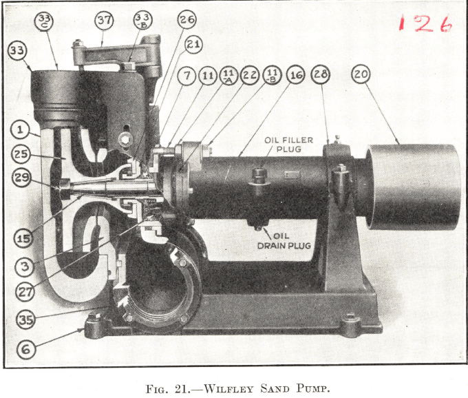
When the pump is not running, the annular opening round the shaft is sealed by the packing ring of the check valve (27). This assembly is mounted on the shaft in the short cylinder (22) and consists essentially of a spider carrying weights and a packing ring held in position by a spring. The chamber in which it revolves is open to the atmosphere through a drainage hole in the bottom. 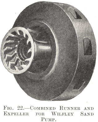 When the pump is started, the weights are moved outwards by centrifugal force, the movement being transmitted to bell cranks, which, acting against the spring, pull the packing ring off its seat on the shaft; the shaft is thus free of rubbing contact as it revolves and consequently is subjected to no wear at any point. When the pump is shut down, the check-valve operates in the reverse way and seals the annular opening so that the slurry cannot penetrate through the short cylinder (22), and damage the bearing assembly in the long cylinder (16).
The slippage seal adjustment regulates the clearance between the runner (25) and the follower plate (3) , which becomes enlarged by wear and causes a gradually increasing circulation, or “ slippage ”, of the discharged slurry back to the intake with a corresponding decrease in the efficiency and capacity of the pump. The clearance can be taken up by loosening the set-screw on the pedestal cap (28) and shifting back the whole cylinder and shaft assembly, comprising the long and short cylinders (16 and 22), the shaft (15), and the runner (25), by manipulating the nuts (11 A and B) on the threaded draw-bolt (11). The bolt is fixed to the frame and passes through a hole on a boss on the long cylinder (16), which can thus be shifted to any desired position. In practice the adjustment is made while the pump is running, the cylinder assembly being drawn back until the runner is heard to rub on the follower plate and then brought slightly forward again.
Replacement of the parts subjected to wear can be effected easily and rapidly in the Wilfley slurry Pump. The intake piping need never be touched. When a replacement is necessary, the discharge piping is raised from the case (1) by loosening two nuts in the side of the discharge keeper assembly (33) and screwing the keeper bolt (33B) upwards ; this action raises the discharge piping just clear of the joint gasket. The case (1) is released by unscrewing its two securing bolts and can then be swung out of the way by means of the crane (37), which is provided to facilitate the removal of this heavy part. The runner (25) can be released by holding the shaft (15) and turning the runner itself so as to unscrew the bolt (29) which holds it in place. The follower plate (3) has only to be lifted off its supporting pins, and the die-ring (26) can be removed after taking out two machine screws. The whole operation of dismantling these parts need only occupy a few minutes. If required, the check valve assembly can be withdrawn as a unit by taking off the short cylinder head (21) while the bearing assembly in the long cylinder (16) is of unit construction so that the barrel can be removed intact and replaced by a spare.
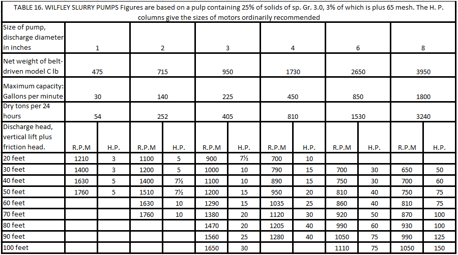
Table 16 gives the manufacturer’s figures for the various sizes of pumps when handling the average class of slurry as specified. If coarser solids are to be elevated or if the slurry is appreciably denser than indicated, the pump speeds should be increased by 50 to 150 r.p.m. Both belt and direct driven models are made, the latter type being the more popular.
Grit Pumps
A pump that is becoming increasingly popular for handling slurry and slime is the Grit Pump made by International Combustion, Ltd. The original model is shown in section in Fig. 23A. Every part of the pump in contact with the slurry—intake piping, pumping chamber, and impeller—can, if necessary, be rubber-lined. Thus, not only gritty material but also acid liquors and corrosive slurry can be handled with minimum wear and tear.
The pumping chamber has a single inlet in the side opposite the driving shaft and is fitted with renewable end-plates of special metal, front and back. The impeller is of the full-way shrouded type with two blades. It is cast in one piece with an expeller, which is similar to that on a Wilfley pump, but is situated on the side opposite the intake opening, its purpose being to keep abrasive material away from the point where the driving shaft enters the pumping chamber. A single hexagon locking nut secures the impeller to the driving shaft so that replacements can be effected quickly and easily.
The space between each end-plate and the corresponding side of the impeller is kept clear of grit and slurry by means of a small stream of water. The latter is introduced at a pressure greater than that of the total effective head (delivery plus suction) through two ¼-in. pipes, one at each side of the impeller, at the points where the driving shaft and the inlet pipe respectively pass through the end-plates. So little abrasive material finds its way against the stream to the sides of the pumping chamber that it is normally unnecessary to line the end-plates and the outer sides of the impeller with rubber; only the intake pipe, the peripheral part of the pumping chamber, and the inside of the impeller need be protected. Should it be necessary to handle an acid liquor or a corrosive slurry—such, for instance, as one containing sea water—the end-plates and impeller are completely covered with rubber so that every part of the pump in contact with the liquid is protected.
The driving shaft runs in two ball or roller bearings placed well clear of the pump itself. A stuffing box in the casing of the pump, filled with grease packing, prevents the pressure water from leaking back along the shaft. No other lubrication is actually necessary at this point, but a grease pipe and nipple are provided, as most operators prefer to take the precaution of adding extra lubricant.
A soft rubber, made by the British Tyre and Rubber Co., Ltd., and attached to the metal surfaces by their Vulcalock Process, is used for the linings. The bond formed between the two surfaces by this method is as strong as the rubber itself.
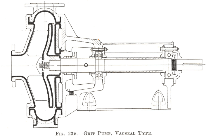
A new model, termed the Vacseal Pump, has been recently introduced (Fig. 23B), in which the front and back covers together with the casing and impeller are rubber-covered, the end-plates being omitted. The main difference from the old model, however, lies in the design of the impeller. This is of the open type with three blades and is provided with an extension on the back consisting of vanes of larger diameter
than the pumping vanes. By these means a suction effect is exerted on the point where the driving shaft enters the pumping chamber which eliminates gland troubles and makes high-pressure sealing water unnecessary. A short gland with three rings of soft packing is provided to prevent the impeller from sucking air and to obviate leakage when the pump is not running. A single hexagon nut secures the impeller to the driving shaft as in the other model.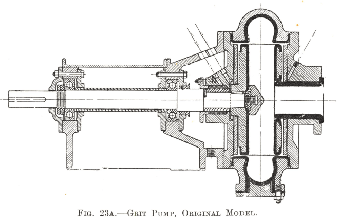
The inlet to the pumping chamber is short and of larger diameter than the discharge pipe in order to allow dense slurry to flow freely to the impeller. The driving shaft runs in two ball or roller bearings placed well clear of the pumping chamber and the stuffing box is readily accessible for packing purposes. The shaft is covered at this point with a sleeve of stainless steel, being thus protected against attack by corrosive liquors when the pump is stationary.
The Vacseal Grit Pump is not so foolproof to run nor so simple to repair as the Wilfley slurry Pump, but it has three advantages over the latter:
- Every part liable to wear by the abrasive action of the slurry is protected by rubber, which has a longer life than metal.
- Every part of the interior is protected from the action of acid or other corrosive liquids.
- Whereas a Wilfley slurry Pump must be provided with an intake head of 4 ft. or more, the Grit Pump will run, if required, with a suction head up to 6 ft.
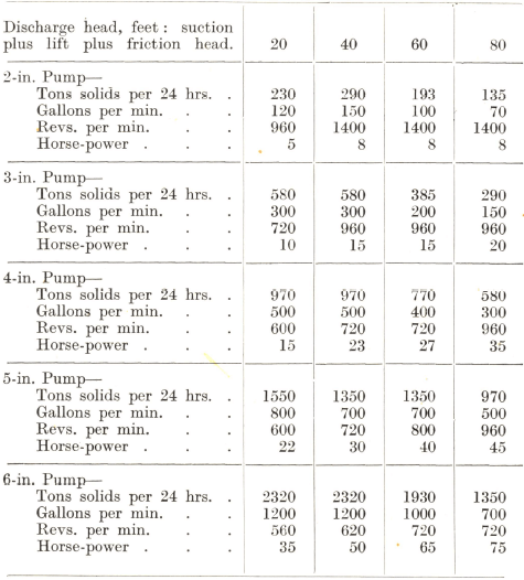
The capacities and power requirements of both models are given in Table 17 on p. 54. The pump is normally provided either with a belt pulley or with a coupling for direct motor drive.
Vertical Centrifugal Slurry Pump

Because of their small size the ¾” and 1″ pumps are mounted on a short base and, on the standard units, wearing parts are replaced by lifting pump off its base. If desired a hinged base, as shown, can be furnished.
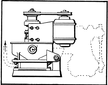
The pumps may be furnished with vertical flanged pulley for flat belt drive, or mule drive attachment with round rubber belts, as shown, for flat or V- belt drive.
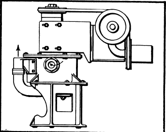
The ¾” and 1″ pumps are ideal for use in continuous laboratory test plants. For this type of installation, where experimental work normally requires frequent flow-sheet changes, it is often convenient to have the pumps mounted on a base with casters as shown.
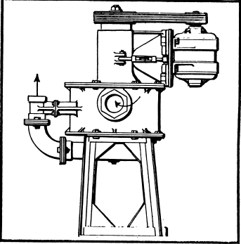
The 3″ and 4″ pumps are furnished as standard with a 19″ high base. If desired a higher than standard base can be furnished on the pumps. The drawing shows a 4″ pump with 36″ high base (distance between bottom of bowl and floor).
Vertical Centrifugal Slurry Pump have long been leaders in the field of difficult pumping problems the pumping of sticky flotation froth, gravity concentrates, deslimed slurry, unit cell concentrates, amalgam barrel tailings, jig hutch products or any slurry containing gritty material. Any material which can be made to flow by gravity to the feed opening can be handled by these revolutionary vertical pumps.
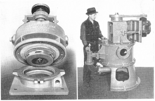
The vertical design of Centrifugal Slurry Pumps, shown at the right, overcomes such common difficulties as stalling, caused by handling difficult slurry containing slurry or coarse material; plugging of pump, caused by use of an intake feed passage; and air locking, caused by intermittent feed or the handling of air laden slurry. Freedom from air locks plus the gravity flow principle eliminates any possibility of surging so that the discharge is at the same rate as the in-flow (up to the maximum capacity).
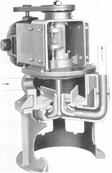
The feed slurry flows directly by gravity into the pump bowl and through the feed opening in top of the runner by means of the suction vortex action. Since the pump contains no intake feed passage, it is impossible to plug the pump while operating, which is an important advantage.
Built in Six Sizes
The new 3″ or 4″ size, shown at the right, was designed to meet a demand for larger capacity pumps for milling plants .
Other sizes include ¾”, 1″, 1½”,and 2″ pumps. These Pumps can be furnished in either motor or belt driven types.
Slurry Pump Manufacturing
The Vertical Centrifugal Slurry Pump consists of a vertical runner assembly with a unit bearing housing employing enclosed ball bearings. The upper bearing is of the deep grooved thrust type, while the lower bearing is of the self-aligning type. Drive is through a V-belt; sheave is keyed to upper- end of the runner shaft far above the floor with its splash and dirt. To the lower end of the tapered threaded shaft is fitted the runner.
The large cast iron pump bowl serves as the feed chamber to the runner and also supports the bearing assembly and the motor mounting, keeping it well away from possible splash and foreign matter. A hinged base can be supplied on the smaller sizes.
The wearing parts of Vertical Centrifugal Slurry Pumps are accurately designed for ease of replacement. These parts consist of Decolloy runner, Decolloy runner case and rubber follower plate. The follower plate can also be furnished in Decolloy—a corrosive and abrasive resisting alloy (high in nickel and chrome) which triples the life obtained with white iron. A replaceable shaft protecting rubber sleeve is also supplied. Special lubrication design insures trouble-free operation.

