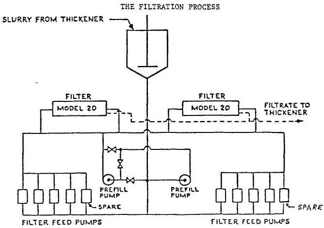
Pilot test results with 30% refuse slurry suggested the installation of two (2) Passavant Pressure Filters, Model 20 with 150 chambers each and a cake thickness of 40 mm. Each filter plate is 2m x 2m in size and the total cake capacity of each filter is 762 cu. feet.
The sludge pumping requirements, per cycle, are approximately 71.92 cu.m. Two fastfill centrifugal pumps furnish 48.68 cu.m. (2,573 gpm average) and the four piston pumps furnish 22.92 cu.m. (242 gpm average).
The Passavant pressure filter Model 20 is of the “overhead design”, i.e. the filter plates are supported from an overhead beam making the plates readily accessible from both sides. Four hydraulic cylinders serve to close the filter and make the stack of filter plates pressure tight.
The filter plates are of a dual chamber design with two feed holes. The center support bar which forms the two chambers also serves to strengthen the filter plates and give the plates the capability to withstand the terminal pressure of 239.7 PSIA on one side. Filter cloth is of the mono filament construction.
When the filtration cycle is completed, the sludge core in the feed openings is blown out by compressed air and the hydraulic mechanism is reversed to push the follower away from the stack of filter plates. Each of the filter plates is suspended from a carriage which, in turn, rests on a track in the overhead beam.
The filter plates shifting device, also housed in the overhead beam, shifts one plate at a time toward the follower. As a plate moves away from its neighbor, the accumulated filter cake drops into a hopper below and onto a conveyor belt. Filter plates are shifted at the rate of four seconds each so that all cake is discharged in about ten minutes. Total “turn around” time, including closing and pressurizing the hydraulic system, is about fifteen minutes with 25 minutes actual filtering time. A complete “run” or cycle, therefore, is approximately 40 minutes.
In this case, the two Passavant pressure filters were installed “in-line”. This orientation was dictated by the shape of limited space available at the wash plant site.
The filters are also equipped with an automatic plate washer which travels on the overhead beam and serves both filter presses and washes the filter cloth by means of high pressure water jets. The device can be made to cycle from one to six times on each plate. The impingement of the water on the filter cloth restores the filter cloth to its original permeability. No operator is required to wash the filter. Washing is usually done on weekends when the coal washer is shut down. In the event that a filter must be washed while the other is in operation, a trap door arrangement beneath the filters is closed so that no wash water will drop onto the conveyor belt.

Two “fastfill” pumps, each having a capacity of 0.16 cu.m/s at 146 t/h when operating at 115.2 l/sec are powered by 149 kw horsepower motors and are arranged to operate in parallel for approximately the first two minutes of the cycle. By this time, the maximum head pressure is reached and automatic valves arrange the two pumps in a “series mode” and the two pumps now operate up to about 154.7 PSIA pressure. At this point, four high pressure piston pumps are started and the centrifugal pumps are shut down.
The piston pumps are driven by hydraulic cylinders which, in turn, limit the pumping pressure to 239.7 PSIA. When the terminal pressure of 239.7 PSIA. is reached, one or more of the high pressure pumps slow down or shut off entirely.
Originally, the system was designed so that the filtrate flow was monitored, i.e. when a predetermined low flow of filtrate was indicated, the system would shutdown and terminate the cycle. In actual practice, the operators find it more convenient to operate the filter on a pre-determined time cycle.
After the wet core is blown back to the feed tank, and thus the filter depressurized, the accumulated filter cake must be discharged. A trap door beneath the filter, closed during filtration, now opens automatically and allows the filter cake to be dropped onto the conveyor belt below. Heavy steel cables are stretched lengthwise which will cut the filter cakes into smaller pieces and thus be handleable by the trough conveyor belt.
At a point outside the filter building, coarse refuse is added to the filter cake and the mixture is conveyed by a belt conveyor to the landfill site. The 6.4 mm coarse refuse coming from preparation plant has been dewatered by drain and rinse screens and the ¼” x 14 mesh size is dewatered by VC-49 centrifugal dryers. This combination of coarse refuse is dewatered to 5.5% total moisture. The filter cake from the presses contains a total moisture of 23% and the two combined provide a total moisture of 9% on final refuse. The mixture of filter cake with approximately 23% moisture and the coarse refuse is very stable in a landfill and will support bulldozing operations.


