Shaker tables, as the name implies, utilized a Shaking action for conveying the refuse and discharging it over the refuse end. The tables were hung from rods attached to overhead supporting beams. A shaft and cam arrangement at one end of the table served as the actuating mechanism and imparted to the table an endwise, back-and-forth, swinging motion. A shaking block was fixed in the proper position at the shaft end, so that the table would strike against it at the end of each backward swing. The hanger rods or stirrups were so adjusted as to give the table a slight uphill slope toward the refuse end; that is, the end next to the driving mechanism. The feed box was near the upper end of the table and designed to spread the mixture of coal and water over the width of the table. Wash water was added a short distance below the feed box. With the table in motion and coal mixed with water being fed to it through the feed box, a certain amount of stratification took place, depositing heavy refuse at the bottom of the bed in contact with the surface of the table. Constant shaking and a certain amount of friction between the refuse and table carried the refuse up the slope and discharged it over the upper end. The top layer of the bed, which was light and consisted mainly of coal, was carried along in the opposite direction by the wash water and was discharged at the lower end of the table as washed coal.
Some of the disadvantages that were inherent in shaking tables but have been overcome in present-day table designs are obvious. Naturally, it was a problem to maintain not only the shaking blocks themselves in a satisfactory state of repair but also the various mechanical parts and structural beams and columns, which suffered wear and tear as a result of the constant pounding action of the tables. More serious than the difficulties connected with the mechanical operation was the inherently limited effectiveness of these tables as coal-cleaning devices. In the first place, the rather violent shaking and agitation of the material in the bed with every impact of the table against the shaking block was by no means conducive to good stratification. In the second place, even if good stratification could have been obtained, high cleaning efficiency would have been precluded by the lack of a really efficient mechanism for the separation of the clean-coal stratum from the underlying refuse. There were no riffles to guide the refuse toward its discharge end nor to aid in maintaining a smooth and uniform movement of the washed coal toward the washed-coal discharge zones. Separation of the upper layers of the bed and their removal to the washed-coal end was dependent entirely on the flow of wash water down the slope in a direction diametrically opposite to the movement of the refuse. Anything more than a comparatively crude separation of wash coal from refuse was not to be expected under these conditions.
An improved type of shaking table (Huntington-Heberlein) has been used rather extensively for coal washing in England in recent years. In this country it is known as the Overstrom Universal and has been used mainly for ore concentration. It embodies the modern type of riffled deck with cross-flowing water, but is retains the shaking principle. The table deck is actuated by an unbalanced loose pulley running on a shaft rigidly clamped to the framework of the deck. At the end of the forward stroke the frame of the deck strikes the shaking block placed at the refuse end of the table. Springs are used to cushion the backward movement of the deck and to accelerate its movement forward. Although this table represents a notable improvement over the Campbell table, it has never been widely accepted by coal-preparation engineers in this country.
Differential Head Motion of Tables
By means of radical changes in design the more serious faults of the original shaking tables have been virtually eliminated from modern tables. The concentrating table is now one of the most dependable and efficient devices obtainable for the cleaning of certain sizes of coal. There are two principal differences of design between the modern table and the original shaking table; namely, (1) the differential-motion feature has been substituted for the camshaft and shaking-block combination for actuating the table, and (2) the riffled deck with cross-flowing water now replaces the former boxlike deck with its longitudinal flow of water and end discharge of the washed coal.
The differential motion imparts to the table a conveying action without resort to shaking. The fundamental effect of this motion is to make the table deck approach its reversing point and recede from it with greater speed at one end of its travel than at the other. It must be remembered that the table deck in its back-and-forth motion comes to a stop at each end of its travel before its direction of movement is reversed. This means that if it approaches one end of its travel with greater speed than the other its rate of retardation must be relatively greater at that end. Hence both the retardation and acceleration are greater at one end than at the other. This imparts to the table a conveying action fully as effective as that obtained by shaking, and with much greater smoothness of mechanical action.
The first table to use a differential-motion mechanism instead of the shaking block was developed between 1896 and 1898 by Arthur Wilfley. It was designed for ore concentration and since the early days of its development it has been used extensively for this purpose. Mention of the Wilfley table is made here not because of its record in connection with coal preparation but because it was the first concentrating table to utilize the differential-motion principle. As a matter of fact, Wilfley tables have never been used extensively for coal washing. When equipped with decks specially designed for coal washing they were known as Massco tables, but the writer has been unable to determine definitely that any of these tables are now in use.
Since introduction of the Wilfley nearly a dozen different makes of tables have been put on the market in this country, all of them designed originally for use in the concentration of ores, and all utilizing the differential-motion principle except the Overstrom Universal table, already referred to, and the Buss table, which is actuated by an ordinary eccentric and pitman. The Buss table obtains its conveying action by having the deck mounted on a set of flexible uprights, which lean with their upper ends toward the drive mechanism. In its back-and-forth motion the deck rides the uprights and describes an arclike path, so that on every forward stroke it tends to pitch the material on the deck toward the refuse end.
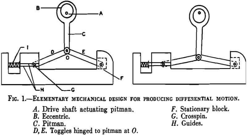
The underlying principle whereby differential motion is obtained is the same in all head motions, although there is some variation in the mechanical designs for application of this principle. The most elementary mechanical illustrations of this principle is shown in Fig. 1. At its outer end toggle E is hinged to a stud in the fixed and stationary block F, while at its outer end toggle D is hinged to a crosspin G, which is free to slide back and forth horizontally in guides H. To the left in Fig. 1 the pitman is at the end of its upward stroke, while to the right it is at the end of its downward stroke.
The relation between the movement of the end of the pitman and the outer end of the toggle D is analogous to the relations in the familiar calculus problem involving a ladder that rests on the ground with one end and leans against the vertical wall of a building with the other. If it is assumed that the ground is level and that the lower end of the ladder is being pulled out along the ground, the downward speed of the upper end of the ladder with relation to the horizontal speed of the lower end is ex-
pressed by the derivative of the function based on the right-angle triangle formed by the ladder, the wall, and the ground, as follows:
dy/dx = – x/√a² – x²
Where a = the length of the ladder,
x = the distance of the bottom of the ladder from the wall,
y = the height of the upper end of the ladder above the ground.
The negative sign merely signifies that y decreases as x increases. This equation can be applied to Fig. 1 by letting the toggle D represent the ladder and a the length of the toggle; x will be the horizontal distance of the lower end of the toggle from the vertical axis of the drive shaft A, and y the vertical distance from the lower to the upper end of the toggle. The upper end of the toggle will not move in an exactly vertical path because the outer end of the toggle E is held by a fixed stud; but for our purpose this can be disregarded, as the effect of it on the dy/dx relation is negligible.
If in the foregoing equation we substitute for x various values of x in terms of a (for instance, x = 0.5a, x = 0.6a, x = 0.7a) and solve for dy/dx we find that as x approaches a in length, dy/dx increases in value. In other words, the farther the crosspin G moves to the left, the less its movement and lower its speed will be with relation to the movement and speed of the end of the pitman. Vice versa, the higher the pitman rises, the faster the crosspin G will move in relation to the movement of the pitman. Although the end of the pitman moves with simple harmonic motion as a result of the uniform angular motion of the shaft A, this harmonic motion is converted to a differential motion in the crosspin G, in accordance with the dy/dx relation explained above.
In the operation of a concentrating table the differential motion is transferred to the table deck by means of a suitable connecting-rod mechanism. In the illustration of Fig. 1 this connection would have to be such as to place the table deck on the right-hand side of the pitman to obtain the accelerated part of the stroke at the outer or refuse end of the table travel. The conveying action would then be toward the end of the table opposite the head motion. As an aid to smooth operation and to overcome effects of lost motion, it is customary to use a coiled spring (1 in Fig. 1) in combination with the pitman and toggle assembly. In some table designs the coiled spring is actually coordinated with the toggle in such a way that the toggle pulls the table deck and compresses the spring on the back stroke, and on the forward stroke the spring is released and pulls the deck forward. Thus, the table is actuated in one direction by the pitman and toggle and in the other direction by the coiled spring.
It has been pointed out that there are some variations in the mechanical designs used for obtaining differential motion. Each table manufacturer uses a design slightly different from those of his competitors. There is no need to describe all these variations in design. The head motions of only the two tables commonly used for coal washing in this country, the Deister-Overstrom and the Plat-O tables, will be discussed here. Reference to the Deister-Overstrom and Plat-O tables is sometimes confusing owing to the fact that they are made by two companies having very similar names, the Deister-Overstrom table being made by the Deister Concentrator Co. and the Plat-O table by the Deister Machine Company.
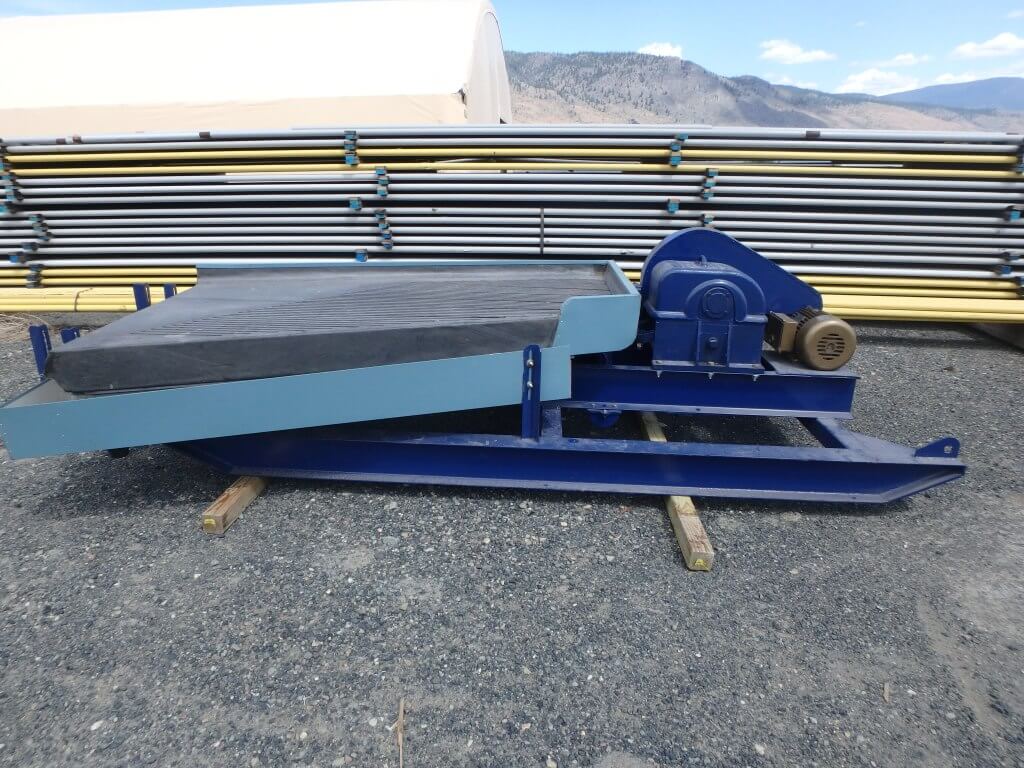
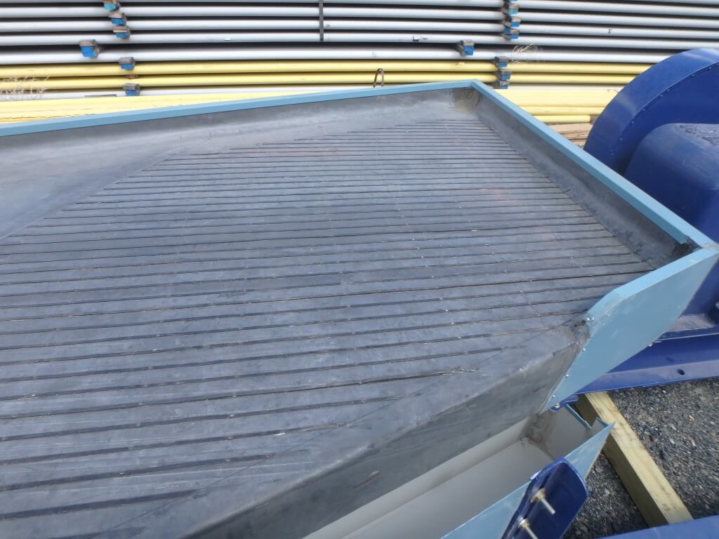
In 1939 the Deister Concentrator Co. introduced the SuperDuty Diagonal-Deck No. 7 coal washing table which has gained wide acceptance.
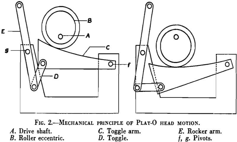
The older Deister-Overstrom and the Plat-O tables employ simple variations of the pitman-and-toggle head-motion design. The principle of the Plat-O head motion is illustrated by the line drawings in Fig. 2. The drive shaft A is fitted with a roller eccentric B, which actuates the toggle arm C. The toggle arm C is connected to the rocker arm E through toggle D. The toggle arm and rocker arm operate from the fixed pivots f and g. The roller eccentric B acts as the pitman and the two illustrations in Fig. 2 show its two extreme positions and the corresponding positions of the toggle arm, toggle, and rocker arm. The table deck would be actuated directly from the upper end of the rocker arm E. A coiled spring is connected between the table frame and the deck near the refuse end in such a way that it is compressed on the backward stroke. On the reverse stroke the deck is carried forward by the energy of the spring.
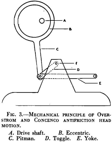
The older Deister-Overstrom table can be operated with either a Deister Heavy Duty or Overstrom head motion. The SuperDuty diagonal deck table is equipped with the Concenco head motion. The two latter use the simple modification of the pitman and toggle design shown in Fig. 3. A is a drive shaft on which is fitted the eccentric B. The pitman C, operated from the eccentric B, is hinged by bearings to the toggles D and to the inside end of yoke E. The other end of toggles D is held by a bearing pin in a fixed block at f. The outer end of yoke E is connected to the deck of the table by a connecting rod. The Concenco antifriction-bearing head motion has been developed rather recently. The only essential difference between it and the Overstrom head motion is that it is equipped with roller and ball bearings arranged for pressure and splash lubrication.
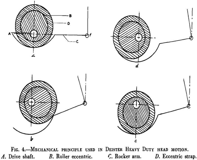
The Deister Heavy Duty head motion is no longer used extensively on coal-washing tables. It is one of the few head motions that give differential motion without the use of a pitman-toggle combination. The differential motion is produced mainly by the device illustrated in Fig. 4, consisting of a drive shaft A, a roller eccentric B, and a rocker arm C, with a circular bearing face at one end and an upright head at the other to accommodate the connecting rod between it and the table deck. The rocker arm is pivoted at f by a bearing pin held rigidly in the frame. A coiled spring under the refuse end of the table deck keeps the left end of the rocker arm in tension against the face of the eccentric roller. Fig. 4 illustrates the positions assumed by the eccentric roller and rocker arm after each successive 90° rotation of the drive shaft. Starting with position a, most of the backward and forward motion of the upright head of the rocker arm takes place during the first and last quadrants of each revolution of the shaft. The result is differential motion with more rapid acceleration and retardation at one end of the rocker-arm range than at the other.
Although the differential action obtained with this mechanism in the Deister Heavy Duty head motion is extremely vigorous, it can be increased further if desired by another device, which is a part of the head-motion assembly. This device operates on the principle that by means of a sliding crank arrangement for transmitting the motion of the drive pulley to the main drive shaft the drive shaft can be given a differential angular velocity. This differential motion of the drive shaft acts in phase with motion of the roller eccentric and rocker arm, increasing further the “kick” or jerk at the outer end of the stroke.
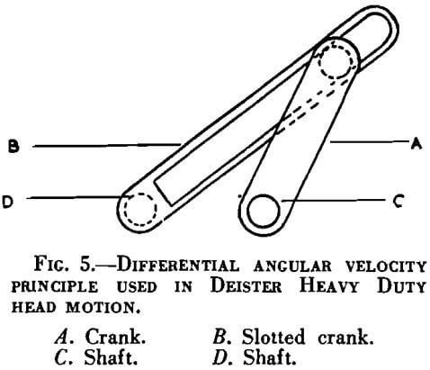
The position of the drive pulley is adjustable with respect to the drive shaft, so that the eccentricity between the pulley and shaft can be varied from zero at one end of the range to a certain maximum at the other. The pulley activates the shaft through a crank, which, being held in a slide at its outer end, functions regardless of how the eccentricity is varied. The principle of the device is illustrated in Fig. 5. The crank A fits in the slotted crank B with one end and is fastened to the shaft C at the other. Crank B is driven by shaft D. The cranks are at the ends of the shafts so that one shaft will not interfere with the rotation of the crank on the other. Now if shaft D rotates, crank A will follow crank B, but when B runs with a uniform angular velocity, A will run with a resulting differential velocity. The greater the eccentricity between shafts D and C, the more pronounced will be the differential angular velocity of shaft C. In the Deister head motion the drive pulley corresponds to crank B and the following crank rotates the main drive shaft carrying the roller eccentric. An adjustment is provided so that the pulley can be set either directly on line with the drive shaft or at varying degrees of eccentricity to it.
Since the introduction of differential motion and the longitudinal riffling with cross-flowing wash water, there have been no radical changes in table design. These two features provided what was required for a completely successful table design and resulted in a very rapidly expanding field for the use of concentrating tables. About 25 years ago, after universal adoption of tables in ore-milling plants, they began to gain popularity in the field of coal preparation in this country. In adapting ore-concentrating tables to coal washing a few modifications had to be made, mainly with respect to riffling and dimensions of the deck. These modifications were easily worked out after a short period of experimental operation in coal-preparation plants.
It is somewhat surprising to find that only two makes of concentrating tables are used extensively for coal washing in this country. The geographical location of table manufactures in relation to the areas where coal washing is carried on extensively may be largely responsible for this situation. The companies manufacturing these tables are both at Fort Wayne, Ind., hence in proximity to the greatest coal-producing areas, whereas other table manufacturers are in the West, where most of the ore milling is done. Although no actual figures are available, probably not less than 95 per cent of all wet-tabling of coal in this country is done on SuperDuty Diagonal Deck and Plat-O tables. With this in mind, some idea of the extent to which wet tables are being used for coal preparation in this country is obtainable from Table 1, which shows approximately the combined number of coal-washing tables in operation in this country, according to information provided by the Deister Concentrator and Deister Machine companies in the fall of 1940. The figures in Table 1 are not to be accepted as 100 per cent correct, as it would be almost impossible to compile such figures without some error, but an effort was made to get the data in this table as nearly correct as possible.
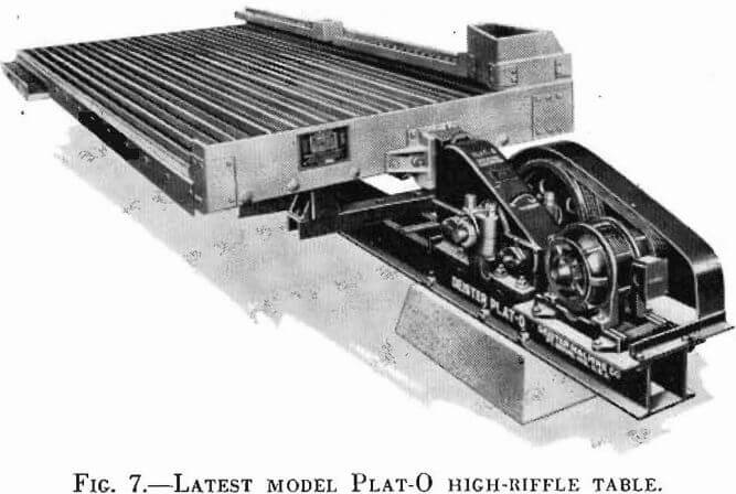
Of the 912 tables listed for the entire country in 1940, 670 were being operated in Pennsylvania. According to the Concentrator Co. and the Deister Machine Co., at least 640 of the tables in Pennsylvania were being used for cleaning anthracite. The rest of the tables in that state and elsewhere throughout the country were being used in preparation of bituminous coal. On the basis of figures for new preparation facilities published annually in the February issues of the magazine Coal Age, about 575 more coal washing tables have been installed since 1940. Of these, about 330 are used on anthracite and the other 245 on bituminous coal. The SuperDuty Diagonal Deck and Plat-O tables are shown in Figures 6 and 7.
