Table of Contents
The press-tails solution going to storage discharges into a spill box (A in drawing), thence passing through a bottom pipe into the barren-solution storage tank. The solution will stand in the spill box at a level depending on the volume of flow, i.e., the volume precipitated. On the side of box A is a smaller screen B connected by pipe to the former so that the solutions stands in it at the same level as in box A. (The screen in this box serves to remove putty which is formed by the residual oils and greases acting with the lime.)
A swivel-jointed pipe C, tapped into the side of screen box B, draws off the press- tails solution in a volume of flow that depends on the height of the solution in the spill box, this volume thus being proportional to the volume precipitated. (In calibrating, pipe C was raised or lowered until the head in spill box A was such as to fill automatic flush tank D in a given time when precipitating a given tonnage.)
Automatic flush tank D, next in line, will thus fill from pipe C and be discharged with a frequency that is dependent on the head in the spill box A and so on the volume precipitated. The press heads are sampled with the same frequency, as will be shown, so that the volume of the sample will likewise be proportionate to the volume precipitated.
Sampling of the press heads is effected as follows
A portion of the press head, or pregnant solution, flows continuously into non¬automatic flush tank F, and as the tank fills, the sample cup shown fills likewise. Each time that the automatic tank D discharges, a vacuum is created in leg E as well as in sample bottle G, owing to the piping hookup shown. This puts the sampling nipple attached to the float also under suction, and when the float has dropped sufficiently as tank F empties, the nipple enters the sampling cup and the contents are sucked over into the jar. To prevent continuous discharge of this tank a vent pipe is provided at I. When its end is uncovered, the vacuum in leg E and the sample bottle G is broken and the tank F is ready for the next cycle.

The sampling nipple is 1/8-in. pipe, but this is too large for satisfactory operation. Therefore, the end was closed with a little metal by an acetylene torch and 1/16-in. hole was drilled.
This apparatus was built around an already existing spill box and storage tank. There is no reason, however, why it cannot be adapted to almost any condition so long as the method employed includes a tank so placed that the head varies with the volume precipitated.
Sampling Barren Solution (Press Tails)
The sample bottles for press tails are kept in a safe so that, if by carelessness the operator allows the press tails to run high, he cannot destroy the evidence. This safe consists of a metal box containing three Winchester bottles. The discharge pipe from the siphon passes through the box, and the sample is drawn off within the box. A small “drip catcher” operated from the outside is used to shift the flow to the various bottles.
In most operating plants the loss of barren solution in final thickener underflows (straight C.C.D. plants) or as moisture in final-stage filter cakes is sufficient to maintain a solution balance that prevents the accumulation of impurities beyond the critical concentration which might interfere with precipitation.
In other cases, it is necessary to discard continuously a certain proportion of barren solution from the system, with or without “flood washing” of filter cakes, which at least ensures very thorough displacement of gold values. The disadvantage of this scheme is that it increases the loss of residual free cyanide and lime over and above that normally lost through filter cake or thickener-underflow moisture content.
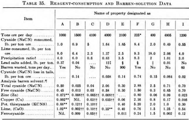
To give an idea of typical reagent consumption and the compositions of barren solution, refer to Table 35, which was prepared from data received by the Dorr Company in 1941 in response to a questionnaire on the subject that was submitted to a number of operating companies.
General
In taking samples of pulp containing cyanide solution, it is the practice at some plants to add a little potassium permanganate solution to the sample container to arrest the solvent action of the cyanide.

