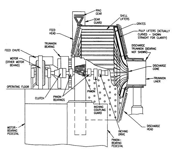
Once the basic operating conditions have been defined for the mill designer then, and only then, can he begin taking into account shell and head stresses and trunnion bearing sizes required to carry the load and to give the required openings for feeding and discharging the mills.
Mill heads are key structural components of any grinding mill. They must carry the load of the shell assembly, liners, media and material in process, and transmit it evenly to the trunnion bearings to assure smooth operation.
Manufacturers in the “big mill business” have long ago recognized that simple extrapolation of existing designs from smaller mills is poor engineering at best.
The stress analysis of a mill head is difficult because of cyclic stresses, complex shape, clamping flange to the mill shell, change in shape from its conical portion to the trunnion portion, the load imposed on the trunnion and the “ovality” of the trunnion. There are many variables (perhaps as many as 20) which affect good head design, such as the conical angle, trunnion length critical thickness, and critical radius just to mention a few.
A field-proven computer program has made possible the performance of multiple calculations to permit analysis of effects of changes in head geometry on critical stress and head weight. These studies have been important in a coordinated optimization program for mill heads, shells and trunnion bearings.
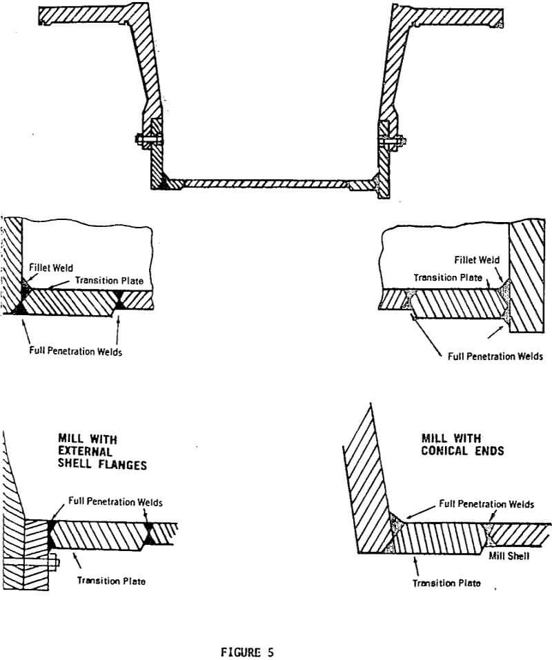
Mill Shells require a similar but more complicated program for stress and deflection analysis. Often, depending on the load concentration and mill length, special shell designs are required. An example is shown on Figure 5. This design features a patented “transition plate” design at the shell cylinder ends to provide additional material cross-sectional area where the stress analysis has shown stresses to be the highest. This heavier section is maintained for a sufficient length until it is known that the operating stresses drop off. The advantage of this type of construction and its efficient use of materials has been proven many times by multiple strain gauge tests in the field.
As mentioned earlier, mills greater than 26′ in diameter and greater than 4,000 horsepower will often feature conical ends usually with radial reinforcing ribs.
Deflection analysis has shown that the conical end produces a structure more stable and rigid than a flat end plate design, when designing mills of the sizes and horsepower mentioned above and larger. Below this size it is possible to design and manufacture mills economically with vertical flat plate ends within the limits of stress, deflection, and practical manufacturing considerations. In large mills it has been found that the use of the conical end plate construction produces a more efficient use of material, with a controlled and predictable stress and deflection pattern due to Its “Belleville sprlng”-like construction.
A recent calculation on a 30′ diameter, 7000 Hp, semi-autogenous mill indicated that a flat end vs. conical end construction would require a shell weighing 13% more to account for stress alone. Deflection was still better in the conical-ended mill as opposed to the flat-ended mill.
Once the head and shell stresses and deflections are accurately predicted and the materials selected the final design can be established.
In considering the shell design, plant location and shipping clearances must be established early in the project schedule. This will determine the extent to which the shell must be sectionalized. The results of these considerations can all be jointly incorporated into plant design, shipping, erection, servicing and the actual mill design.
Experience in sectionalizing big mill shells is invaluable. Machined flanges with bolted connections are the proven “tried and true” method of field assembly. Field welding of shell joints of semi-autogenous or autogenous mill shells has, to our knowledge, yet to be attempted or achieved successfully.
The mill trunnion bearings are a key assembly in mill operation. If the trunnion bearings are not reliable the complete mill is not reliable. Various trunnion bearings designs are used, ranging from fully hydrodynamic to fully hydrostatic.
The design charge load defined earlier is a direct input in the calculation of the trunnion bearing pressure. Rearing pressures are most accurately calculated when based on total rotating mill assembly weight plus total design charge weight. Then, by taking moments around each trunnion bearing for these components, determine the load which the bearing actually “sees.”
If the mill is to feature reversible rotation (as many autogenous mills do) it is vitally important that the trunnion bearings be fully self-aligning, so that “hot spots”, due to a cocked bearing that does not perfectly align itself with the trunnion, do not become a problem.
The type of drive and drive design used on a given mill, especially with respect to the motor type, is directly influenced by the study of the owner’s electrical system. Manufacturing limitations from gear vendors determine the minimum number of pinions which can be used to drive the mill as well as the number of gear sections.
If the mill requires approximately 6000 horsepower or less, it is possible to drive it with a single pinion. To date, however, economics has dictated that most mills over 3500 horsepower be driven with two pinions, using wound rotor motors driving thru speed reducers.
Wound rotor motors are inherently load sharing, however power factor correction by the use of capacitors is often required. Attention must be paid to the motor design and the secondary control so that the total resistance which each motor “sees” is the same for load balancing purposes. Often the use of the “trimming resistor” is advantageous in the initial no-load mill runs in order to balance out each leg of the drive train. The use of wound rotor motors also provides for a low inrush situation, if the power system study demands it, and makes mill speed variation possible. This variation comes generally at a sacrifice in motor efficiency because the reduced power demand from the mill is lost in the speed control circuit.
As mentioned above if the power is approximately 6000 horsepower or less a single pinion can be used, allowing the use of a synchronous motor and air clutch for low inrush applications. This provides the advantages of power factor correction through the synchronous motor. If an “across the line” start is allowable, the air- clutch can be eliminated and a high torque synchronous motor used, either of the low speed type or a high speed type thru a gear box.
If the advantages of a synchronous motor are desired on any dual pinion drive application, dual synchronous motors are available to drive dual pinion gear arrangements featuring load sharing control devices. These continuously monitor individual mill power and adjust each motor with respect to the.other, such as the D.C. field, to achieve a balanced load division to the gearing. Until more experience is gained on this type of drive, Allis-Chalmers and major gear drive vendors advise adding a safety factor of 10% to the gear/reducer/coupling rating, in order to allow for the possible unbalanced load division in this drive train. As experience is gained on this type of drive it is expected that this extra safety factor can either be reduced or eliminated.
Beyond 6000 horsepower per pinion or 12,000 horsepower for two pinions, other drive schemes must be considered. The obvious solution is to use more pinions, say, four per mill, with each pair coupled to the output shafts of a special single-input/double-output reducer — two reducers and two motors per mill. The problems of load division remain in this case, both in the reducers and in the motors.
Another solution is to use the so-called “gearless drive.” A cyclo-converter reduces the power frequency and a synchronous motor is either wrapped around shell or mounted on a trunnion extension. This makes the mill essentially a part of a synchronous .motor rotor with the stator in its usual position around the rotor.
Inherent in this type of drive is limited speed variation. This has many interesting implications with regard to mill automation where ores are variable. This feature may prove to be one of the main attractions in the first application of this type of drive to either an autogenous or semi-autogenous type mill.
Gearless drives have some drawbacks such as the need to maintain the air gap between the rotor and stator, which becomes a function of trunnion bearing wear. In addition, although technically a synchronous motor, this drive design has a power factor and efficiency lower than those typical of wound rotor motors. On the other hand, a slow start is inherent and the inrush is lower than a wound rotor motor or a synchronous motor. We expect to see more of this type of drive in the future on autogenous mills. There are a number of mills in the cement industry in Europe, which have operated for more than three years with this type of drive.
Reversible rotation is often used to obtain balanced wear on mill liners and lifters, to reduce the number of mill shutdowns. This feature can easily be incorporated into dual pinion or gearless drives. With proper design, single pinion drives can also be made reversible. Attention must be paid to the direction and magnitude of the forces on pinion bearing housings.
