Table of Contents
- Types of Grinding Mills Manufactured
- How much grinding power is needed
- Mill speed and grinding charge volume
- Grinding Media
- Mill Power
- Grinding Mill Design
- MILL SHELL
- HEADS AND TRUNNIONS
- MILL TRUNNION BEARINGS
- MILL RING GEAR
- MILL PINION
- MILL LUBRICATION SYSTEMS
- MILL LINERS
- Mill FEED AND DISCHARGE Head ARRANGEMENTS
- Grinding Mill Specifications Data
- Grinding Mill Support Equipment
All Ball Mill Manufacturers understand the object of the grinding process is a mechanical reduction in size of crushable material. Grinding can be undertaken in many ways. The most common way for high capacity industrial purposes is to use a tumbling charge of grinding media in a rotating cylinder or drum. The fragmentation of the material in that charge occurs through pressure, impact, and abrasion.
Grinding is converting energy. When the grinding charge is forced to tumble the motor energy is converted into new particle surface and heat.
An important point for the economy is that the size of the grinding media suits the material to be ground.
The choice of mill design depends on the particle size distribution in the feed and in the product wanted. Often the grinding is more economic when executed in a primary step, followed by a secondary step, giving a fine size product.
As experts in crushing and grinding – can offer a full range of grinding mill types and sizes. Our mills are identified by codes of letters:
C=central trunnion discharge
P=peripheral discharge
R=spherical roller trunnion bearing, feed end
H=hydrostatic shoe bearing, feed end
R=spherical roller trunnion bearing, discharge end
K=ring gear and pinion drive
CRRK is the common type in wet grinding. The PRRK-series is often used for dry grinding in rod mills, and in certain ball mill applications.
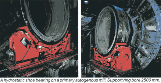
Type CHRK is designed for primary autogenous grinding, where the large feed opening requires a hydrostatic trunnion shoe bearing. Small and batch grinding mills, with a diameter of 700 mm and more, are available. These mills are of a special design and described on special request by all Ball Mill Manufacturers.
Types of Grinding Mills Manufactured
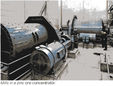
The different types of grinding mills are based on the different types of tumbling media that can be used: steel rods (rod mills), steel balls (ball mills), and rock material (autogenous mills, pebble mills).
ROD MILLS
The grinding charge in a rod mill consists of straight steel rods with an initial diameter of 50-100 mm. The length of the rods is equal to the shell length inside the head linings minus about 150 mm. The rods are fed through the discharge trunnion opening. On bigger mills, which need heavy rods, the rod charging is made with a pneumatic or manual operated rod charging device. The mill must be stopped every day or every second day for a few minutes in order to add new rods and at the same time pick out broken rod pieces.

As the heavy rod charge transmits a considerable force to each rod, a rod mill can not be built too big. A shell length above 6100 mm can not be recommended. As the length to diameter ratio of the mill should be in the range of 1,2-1,5, the biggest rod mill will convert maximum 1500 kW.

Rod mills are used for primary grinding of materials with a top size of 20-30 mm (somewhat higher for soft materials). The production of fines is low and consequently a rod mill is the right machine when a steep particle size distribution curve is desired. A product with 80% minus 500 microns can be obtained in an economical manner.
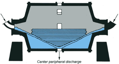
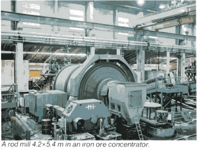
The CRRK series of wet grinding rod mills are tabulated below.
The grinding charge in a ball mill consist of cast or forged steel balls. These balls are fed together with the feed and consequently ball mills can be in operation for months without stopping. The ball size is often in the diameter range of 20-75 mm.
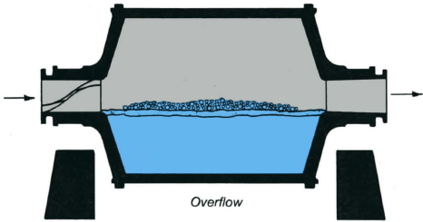
The biggest size is chosen when the mill is used as a primary grinding mill. For fine grinding of e.g. sands, balls can be replaced by cylpebs, which are heat treated steel cylinders with a diameter of 12-40 mm and with the same length as the diameter.
Ball mills are often used as secondary grinding mills and for regrinding of middlings in concentrators.
Ball mills can be of the overflow or of the grate discharge type. Overflow discharge mills are used when a product with high specific surface is wanted, without any respect to the particle size distribution curve. Overflow discharge mills give a final product in an open circuit. Grate discharge mills are used when the grinding energy shall be concentrated to the coarse particles without production of slimes. In order to get a steep particle size distribution curve, the mill is used in closed circuit with some kind of classifier and the coarse particles – known as classifier underflow – are recycled. Furthermore, it should be observed that a grate discharge ball mill converts about 20% more energy than an overflow discharge mill with the same shell dimensions.
Ball mill shells are often furnished with two manholes.
Ball mills – with small balls or cylpebs – can produce the finest product of all tumbling mills. 80% minus 74 microns is a normal requirement from the concentrators. The CRRK series of wet grinding ball mills are tabulated below.
PEBBLE MILLS
No steel grinding media is used in a fully autogenous mill. When choosing primary autogenous grinding, run of mine ore up to 200-300 mm in size is fed to the mill. When using a crushing step before the grinding, the crusher setting should be 150-200 mm. The feed trunnion opening must be large enough to avoid plugging. The biggest pieces in the mill are important for the size reduction of middle size pieces, which in their turn are important for the finer grinding. Thus the tendency of the material to be reduced in size by pressure, impact, and abrasion is a very important question when primary autogenous grinding is proposed.

When autogenous grinding is used in the second grinding step, the grinding media is size-controlled and often in the range of 30-70 mm. This size is called pebbles and screened out in the crushing station and fed to the mill in controlled proportion to the mill power. The pebble weight is 5-25% of the total feed to the plant, depending on the strength of the pebbles. Sometimes waste rock of high strength is used as pebbles.
Pebble mills should always be of the grate discharge type. The energy that can be converted in a mill depends on the total weight of the grinding charge. Consequently, pebble mills convert less power per mill volume unit than rod and ball mills.
High quality steel rods and balls are a considerable part of the operating costs. Autogenous grinding should, therefore, be considered and tested when a new plant shall be designed. As a grinding mill is built to last for decades, it is more important to watch the operation costs than the price of the mill installation.
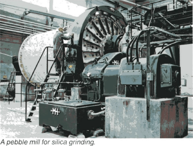
The CRRK series of wet grinding pebble mills are tabulated below.
Selecting Wet or Dry Grinding Mill
Wet grinding is definitely the most usual method of grinding minerals as it incorporates many advantages compared to dry grinding. A requirement is, however, that water is available and that waste water, that can not be recirculated, can be removed from the plant without any environmental problems. Generally, the choice depends on whether the following processing is wet or dry.
When grinding to a certain specific surface area, wet grinding has a lower power demand than dry grinding. On the other hand, the wear of mill lining and grinding media is lower in dry grinding. Thus dry grinding can be less costly.
A closed circuit dry grinding system is very space consuming because of the classifier, the transport devices, the dedusting filter, etc.
The feed to a dry grinding system must be dried if the moisture content is high. A ball mill is more sensitive to clogging than a rod mill. An air stream through the mill can reduce the moisture content and thus make a dry grinding possible in certain applications.
A rod mill has a reduced capacity when used for dry grinding. The material is hindered by the rods when passing from the feed end to the discharge area. Peripheral discharge is recommended.
Due to the hindering effect that the ball charge gives to the material flow in dry grinding, the ball charge is not more than 28-35% of the mill volume. This should be compared with 40-45% in wet grinding. The expression used for this phenomenon is that the charge in a dry grinding mill is swollen.
Big dry grinding ball mills are often two-compartment mills, with big balls in the first compartment and small balls or cylpebs in the second one. An extra grate wall is used to separate the two charges.
The temperature can increase considerably in dry grinding mills, and rubber lining should not be considered.
The efficiency of wet grinding is affected by the percentage of solids.
If the pulp is too thick, the grinding media becomes covered by too thick a layer of material, which hinders grinding. The opposite effect may be obtained if the dilution is too high, and this may also reduce the grinding efficiency. A high degree of dilution may sometimes be desirable in order to suppress excessive slime formation.
Data given for tabulated mill sizes below are in respect of wet grinding. Corresponding data for dry grinding are given upon request.
How much grinding power is needed
The specific power required for a certain grinding operation, usually expressed in kWh/ton, is a function of both the increase in the specific surface of the material (expressed in cm²/cm³ or cm²/g) and of the grinding resistance of the material. This can be expressed by the formula
E = c · (S-So)
where c is a material constant representing the grinding resistance, and So and S are the specific surfaces of the material before and after the grinding operation respectively. The formula is an expression of Rittinger’s Law which is shown by tests to be reasonably accurate up to a specific surface of 10,000 cm²/cm³.
When the grinding resistance c has been determined by trial grinding to laboratory scale, the net power E required for each grinding stage desired may be determined by the formula, at least as long as Rittinger’s Law is valid. If grinding is to be carried out not to a certain specific surface S but to a certain particle size k, the correlation between S and k must be determined. The particle size is often expressed in terms of “particle size at e.g. 95, 90 or 80% quantity passing” and is denoted k95, k90 or k80.
When the screen analyses for the raw material and the product respectively are known, the gross mill power required may be calculated by the following formula proposed by F. Bond:
E = Eo (√100/k80p – √100/k80f)
where E =the specific power consumption expressed in kWh/short ton.
Eo = a proportionality and work factor called “work index”
k80p = particle size of the product at 80% passage (micron)
k80f =the corresponding value for the raw material (micron)
The value of Eo is a function of the physical properties of the raw material, the screen analyses of the product and raw material respectively, and the size of the mill. The value for easily-ground materials is around 7, while for materials that have a high grinding resistance the value is around 17.
Eo is correlated to a certain reduction ratio, mill diameter etc. Corrections must be made for each case.
The simplest method of calculating the specific power consumption is test grinding in a laboratory mill, and comparison of the results with a known reference material. The sample is ground in batches for 3, 6,12 minutes, a screen analysis is carried out after each period, after which the specific surface is determined. A good estimate of the grinding characteristics of the sample can be obtained by comparison of the specific surfaces with corresponding values for the reference material.
When the net power required has been determined, an allowance is made for mechanical losses. The gross power requirement thus arrived at, should with a satisfactory margin be utilised by the mill selected.
Mill speed and grinding charge volume
The critical speed of a rotating mill is the RPM at which a grinding medium will begin to “centrifuge”, namely will start rotating with the mill and therefore cease to carry out useful work. This will occur at an RPM of ncr, which may be determined by the formula

where D is the inside diameter in meters of the mill. Mills are driven in practice at a speed corresponding to 60-80% of the critical speed, the choice of speed being influenced by economical considerations. Within that range the power is nearly proportional to the speed.
The charge volume in the case of rod and ball mills is a measure of the proportion of the mill body that is filled by rods or balls. When the mill is stationary, raw material and liquid should fill the voids between the grinding media, in order that these should be fully utilized.
Maximum mill efficiency is reached at a charge volume of approximately 55%, but for a number of reasons 45-50% is seldom exceeded. The efficiency curve is in any case quite flat about the maximum.
In overflow mills the charge volume is usually 40%, while there is a greater choice in the case of grate discharge mills.
Grinding Media
When calculating the weight of the grinding medium charge weight, the voids ratio for rods may be taken to be 30% and for balls 42%.
The weight per volume will thus be
for steel rods approx. 5.5 t/m³
for steel balls approx. 4.6 t/m³
For coarse grinding in rod mills, the rods used have a diameter of 50-100 mm and their lengths are approx. 150 mm below the effective inside shell length. Rods will break when they have been worn down to about 20 mm and broken rods must from time to time be taken out of the mill since otherwise they will reduce the mill capacity and may cause blockage through piling up. The first rod charge should also contain a number of rods of smaller diameter.
It may be necessary to charge the mill with rods of smaller diameter when fine grinding is to be carried out in a rod mill. Experience shows that the size of the grinding media should bear a definite relationship to the size of both the raw material and the finished product in order that optimum grinding may be achieved. The largest grinding media must be able to crush and grind the largest pieces of rock, while on the other hand the grinding media should be as small as possible since the total active surface increases in inverse proportion to the diameter.
Olewski states that the suitable largest ball diameter in mm can be calculated from the formula
D = 6 · √d • log dk
where d is the size of the largest particle in mm in the feed and dk is the size of the largest particle in microns in the product.
The initial charge should however include balls of several smaller sizes than the maximum. A usual rule is that the weights of the different ball diameters should be in proportion to these diameters.
Example:
A crushed mineral whose largest particles pass a screen with 25 x 25 mm apertures shall be ground to approx. 95% passing 0.1 mm in a 2.9 x 3.2 m ball mill of 35 ton charge weight. In accordance with Olewski’s formula
D = 6 · √25 · log 100 = 60
that is, the largest balls in the first charge should be 60 mm diameter.
If we assume that the mill will in addition be charged with 50, 40 and 30 mm balls, the distribution will be

Once the grinding operation has reached a steady condition, only the largest ball size – as given above – will normally be charged.
Grinding media wear away because of the attrition they are subjected to in the course of the grinding operation, and in addition a continuous reduction in weight takes place owing to corrosion. The rate of wear will in the first place depend on the abrasive properties of the mineral being ground and naturally also on the hardness of the grinding media themselves.
The wear of rods and balls is usually quoted in grammes per ton of material processed (dry weight) and normal values may lie between 100 and 1500 g/ton. Considerably higher wear figures may however be experienced in fine wet grinding of e.g. very hard siliceous sand.
A somewhat more accurate way of expressing wear is to state the amount of gross kWh of grinding power required to consume 1 kg of grinding media. A normal value in wet grinding is 15 kWh/kg. The wear figures in dry grinding are only 10-30 % of the above.
Mill Power
As may be seen on the figure opposite, the power required to drive the mill is, in the equilibrium condition,
N = c · W · Rg · n KW
where c is a constant which, inter alia, takes into consideration the mean slope a of the charge,
W is the weight in kp of the charge
n is the RPM
Rg is the distance in metres of the centre of gravity from the mill centre
If N is taken to be the gross mill power, values of the factor c in wet grinding mills will be
rod mills 1/1800
ball mills, grate discharge 1/1200
ball mills, overflow type 1/1470
pebble mills 1/1200
W for rod and ball mills shall be taken as the weight of the rod or ball charge, i.e. the weight of the pulp is to be ignored. For pebble mills therefore W is to be calculated on the basis of the bulk weight of the pebbles.
Values of power consumption stated in the tables below have been calculated using the above formula.
It should be pointed out that factor “c” in the formula is a function of both the shape of the inner lining (lifter height etc.) and the RPM. The formula is however valid with sufficient accuracy for normal speeds and types of lining.
The diagram gives the values of the quantity Rg/d as a function of the charge volume, the assumption being that the charge has a plane surface and is homogeneous, d is the inside diameter of the mill in metres. The variation of the quantity a/d, where a is the distance between the surface of the charge and the mill centre, is also shown in the same figure.

Grinding Mill Design
Morgardshammar started to design and deliver grinding mills in the beginning of the century. Today the mills are computer designed and manufactured in big plants with modern machinery.
In order to keep manufacturing costs at a minimum level, Morgardshammar has a series of standard mill diameters up to and including 6.5 m. Shell length, however, can be varied and tailor made for each application. The sizes selected are shown on the tables on page 12-13 and cover the power range of 200-5000 kW.
MILL SHELL
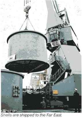
Shells with a diameter of up to about 4 m are made in one piece. Above this dimension, the shell is divided into a number of identical pieces, bolted together at site, in order to facilitate the transport. The shell is rolled and welded from steel plate and is fitted with welded flanges of the same material. The flanges are machined in order to provide them with locating surfaces fitting into the respective heads. The shells of ball and pebble mills are provided with 2 manholes with closely fitting covers. The shells have drilled holes for different types of linings.
HEADS AND TRUNNIONS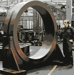
Heads with a diameter of up to about 4 m are integral cast with the trunnion in one piece. Above this diameter the trunnion is made as a separate part bolted to the head. The head can then be divided in 2 or 4 pieces for easy transport and the pieces are bolted together at site. The material is cast steel or nodular iron. The heads and the trunnions have drilled holes for the lining.
MILL TRUNNION BEARINGS
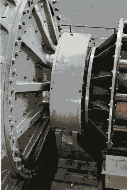 Spherical roller (antifriction) bearings are normally used. They offer the most modern and reliable technology and have been used for many years. They are delivered with housings in a new design with ample labyrinth seals.
For very large trunnions or heavy mills, i.e. for primary autogenous grinding mills. Morgardshammar uses hydrostatic shoe bearings. They have many of the same advantages as roller bearings. They work with circulating oil under pressure.
SHORT TRUNNION
The spherical roller bearing and the hydrostatic shoe bearing take a very limited axial space compared to a conventional sleeve bearing. This means that the lever of the bearing load is short. Furthermore, the bending moment on the head is small and as a result of this, the stress and deformation of the head are reduced.
Ask Morgardshammar for special literature on trunnion bearings.
MILL RING GEAR
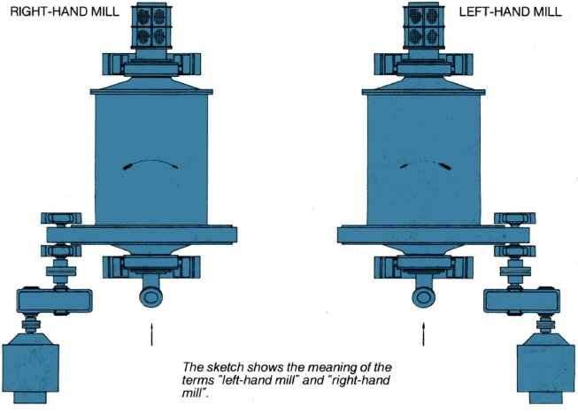
Ring gears are often supplied with spur gears. They are always split in 2 or 4 pieces in order to facilitate the assembly. Furthermore, they are symmetrical and can be turned round in order to make use of both tooth flanks. The material is cast steel or nodular iron. They are designed in accordance with AGMA. The ring gear may be mounted on either the feed or the discharge head. It is fitted with a welded plate guard.
MILL PINION
The pinion and the counter shaft are integral forged and heat treated of high quality steel. For mill power exceeding about 2500 kW two pinions are used, one on each side of the mill (double-drive). The pinion is supported on two spherical roller bearings.
MILL LUBRICATION SYSTEMS
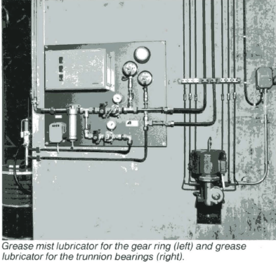
The trunnion bearings are lubricated by means of a small motor- driven grease lubricator. The gear ring is lubricated through a spray lubricating system, connected to the electric and pneumatic lines. The spray nozzles are mounted on a panel on the gear ring guard.
MILL LINERS
In order to protect the parts of the mill that come into contact with the material being ground, a replaceable lining of wear-resistant material is fitted. This may take the form of unalloyed or alloyed rolled or cast steel, heat treated if required, or rubber of the appropriate wear resistant quality. White cast iron, unalloyed or alloyed with nickel (Ni-hard), may also be used.
The shape of the mill lining is often of Lorain-type, consisting of plates held in place between lifter bars (or key bars) of suitable height bolted on to the shell. This system is used i.e. of all well-known manufacturers of rubber linings. Ball mills and autogenous mills with metal lining also can be provided with single or double waved plates without lifter bars.
In grate discharge mills the grate and the discharge lifters are a part of the lining. The grate plates with tapered slots or holes are of metal or rubber design. The discharge lifters are fabricated steel with thick rubber coating. Rubber layer for metal linings and heavy corner pieces of rubber are included in a Morgardshammar delivery as well as attaching bolts, washers, seal rings, and self-locking nuts. A Morgardshammar overflow mill can be converted into a grate discharge mill only by changing some liner parts and without any change of the mill.
Trunnion liners are rubber coated fabricated steel or cast steel.
In grate discharge mills the center cone and the trunnion liner form one piece.
Mill FEED AND DISCHARGE Head ARRANGEMENTS
Spout feeders of Ni-hard have grown popular during the last decade. Feed boxes of fabricated steel with spout feeders can be carried on flanged wheels on rails, thus making disconnecting very easy.
Drum feeders are often used when the flow into the mill is limited. This type of feeder has an inside coating of wear rubber.
Scoop feeders in combination with drum feeders are used when retaining oversize from a spiral or rake classifier. As hydrocyclones are used in most closed grinding circuits the spout feeders are used most frequently.
Vibrating feeders or screw feeders are used when charging feed to dry grinding mills.
Trommel screens are used to protect slurry pumps and other transport equipment from tramp iron. Screens can have perforated rubber sheets or wire mesh. The trommel screens are bolted to the discharge trunnion lining.
 |
 |
 |
 |
 |
 |

 |
 |
Grinding Mill Specifications Data
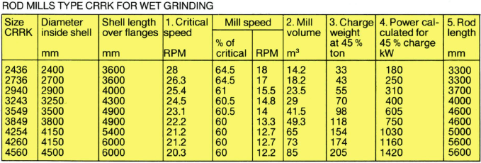
- According to formula 42.3/√d, where d is equal to internal shell diameter within new liners.
In this case the thickness used was 60 mm for small mill sizes up to and including 2940 and 80 mm for larger mills. - Volume of the cylindrical mill proper within new liners.
- Rod length as shown in last column and a bulk weight of 5.5 kg/dm³.
- According to the empirical formula P =W·Rg·n/1800 (kW), where n is mill speed, Rg the radius of the centre of gravity and W the charge weight (kg) according to the table. Rg=0.235·d at 45 per cent charge volume.
- Rod length 150 mm shorter than available space between headliners.
Ask Morgardshammar for dry grinding rod mills and mills for special applications.

- According to formula n = 42.3/√d, where d is equal to internal shell diameter within new liners.
In this case the thickness used was 60 mm for small mill sizes up to and including size 2939 and 75 mm for larger mills. - Approximately 75 per cent of critical speed.
- Volume of the cylindrical mill proper within new liners.
- Same as 3 but with a length deduction of 300 mm (up to and including size 2939) or 400 mm (from size 3236 and up) for the discharge chamber.
- At a bulk weight for balls of 4.6 kg/dm³ and a charge volume of 40 per cent for overflow and 45 per cent for discharge mills.
- According to the empirical formula P = W·Rg·n/1470 (kW), where n is mill speed, Rg the radius of the centre of gravity and W the charge weight (kg) according to the table. Rg = 0.255·d at 40 per cent charge volume.
- According to the empirical formula P = W·Rg·n/1200 (kW), where Rg = 0.235 d at 45 per cent charge volume. See further note 6.
Ask Morgardshammar for dry grinding ball mills and mills for special applications.
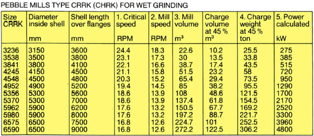
- According to formula n = 42.3/√d, where d is equal to internal shell diameter (m) within new liners. 75 mm was used as liner thickness.
- Approximately 75 per cent of critical speed.
- Volume of the cylindrical mill proper within new liners with half-worn liners according to note 1.
- At a bulk weight of 2.5 kg/dm³ for the grinding pebbles.
- According to the empirical formula P = W·Rg·n/1200 (kW), where n is mill speed, Rg the radius of the centre of gravity (m) and W the charge weight (kg). At 45 per cent charge volume Rg is equal to 0.235 d, where d is the internal diameter (m).
Grinding Mill Support Equipment
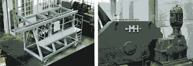
We have has designed a series of single stage speed reducers, which makes it possible to drive the mills by motors with a synchronous speed of 750-1000 RPM.
Inching units for slow rotation of the mills are also furnished.
Rods to the rod mills are charged by means of manual or automatic rod charges.
Erection cradles on hydraulic jacks are used when erecting medium or big size mills at site.
 |
|
 |
 |
 |
 |
