Table of Contents
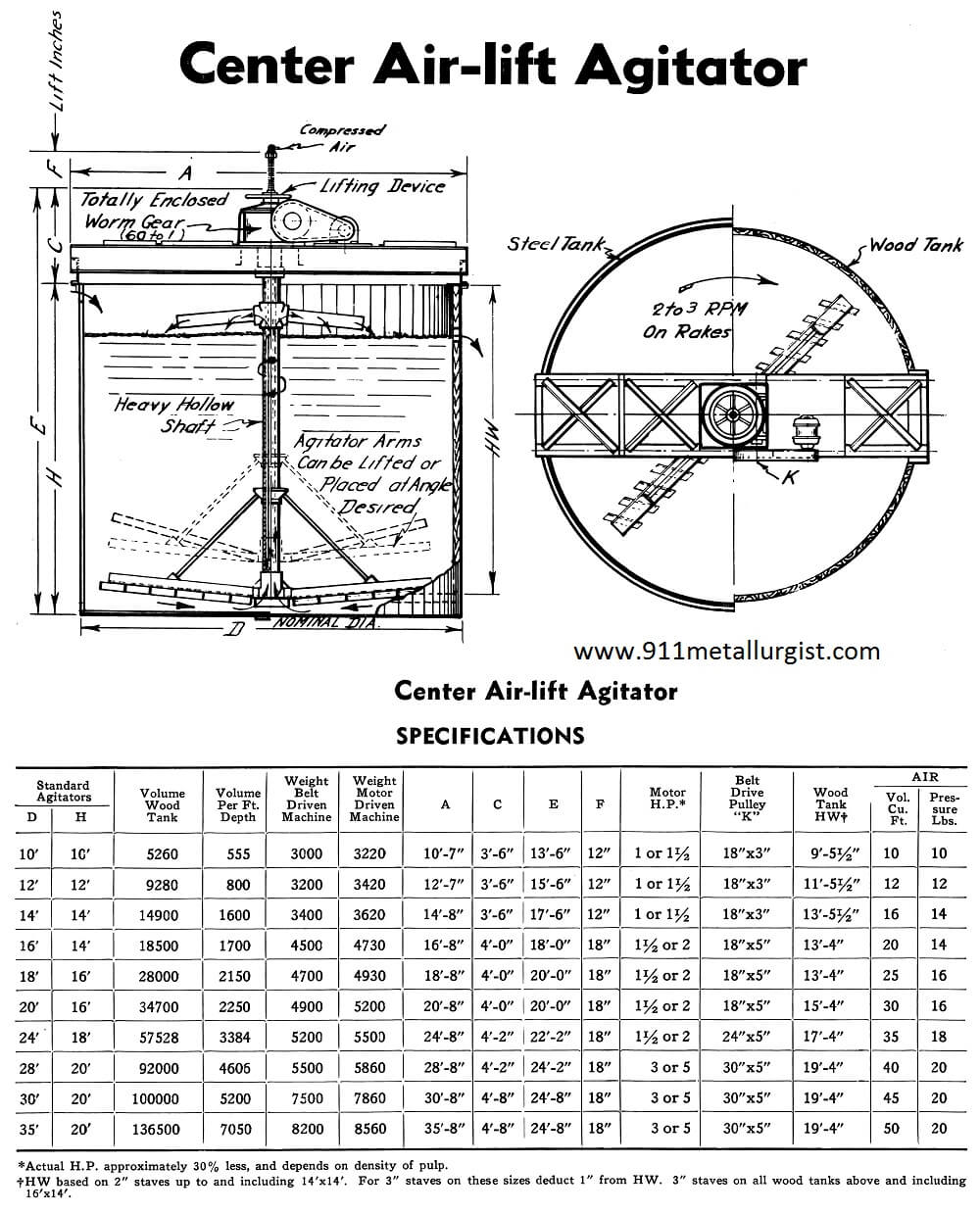
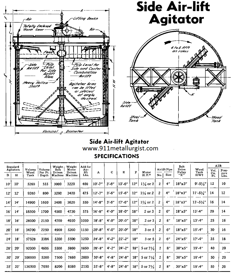
Any Air-lift Agitator is readily convertible from one to another of three general types. Center Air-lift, Side Air-lift or combined Side and Center Air-lift. Each type has its own advantages and application. No matter which type of Air-lift Agitator you have, it is the basis for any of the three general types, for each type has hollow revolving center shaft so that air can be added for Center Air-lift. A unit acquired originally for use as a Center Air-lift type, need only have the Side Air-lift pipes installed, the angle of the rakes changed and the R.P.M. of the rakes increased, to use it as a Side Air-lift type.
Totally Enclosed Head Motions
The basis of all three types is the totally enclosed, running-in-oil head motion, with integral rake lifting device. The head motions of all three types are equipped with hollow center shafts, so that air can be introduced for Center Air-lift.
The rake lifting device is particularly advantageous when starting up after a shutdown where it eliminates damage to shaft and rakes. The rakes, after having been elevated out of the settled solids, can then be lowered gradually.
Adjustable Rakes
The rake arms may be adjusted to any angle from horizontal up to 45 degrees to suit operating conditions. The rakes themselves may be changed in angle, to rake material toward the center, or toward the periphery of the tank.
Operation
In the Center Air-lift Agitator-Conditioner, the rakes are set at an angle to rake the settled material toward the center, where the air-lift raises it to the surface and discharges it into the tank by means of revolving launders.
In the Side Air-lift type the rakes move the material toward the periphery of the tank where the side air-lifts carry it to the surface.
In the Combined Side and Center Air-lift type the rakes move the material toward the center where the Center Air-lift acts upon it, while at the same time the Side Air-lifts elevate any material near the periphery of the tank.
The Center Air-lift type operates at lower speed and takes less horsepower. A speed of 2 to 3 R.P.M. is normal for the Center Air-lift type and 4 to 6 R.P.M. for the Side Air-lift type. This accounts for the lower horsepower required on the Center Airlift type.
This Air-lift Agitator, due to its simplicity and its totally enclosed head motion with integral rake-lifting device, is the improved, economical type to keep pulp in agitation, give controlled addition of air or gas and operate successfully after shutdowns.
SUPER-AGITATOR AND CONDITIONER
Conditioner Construction
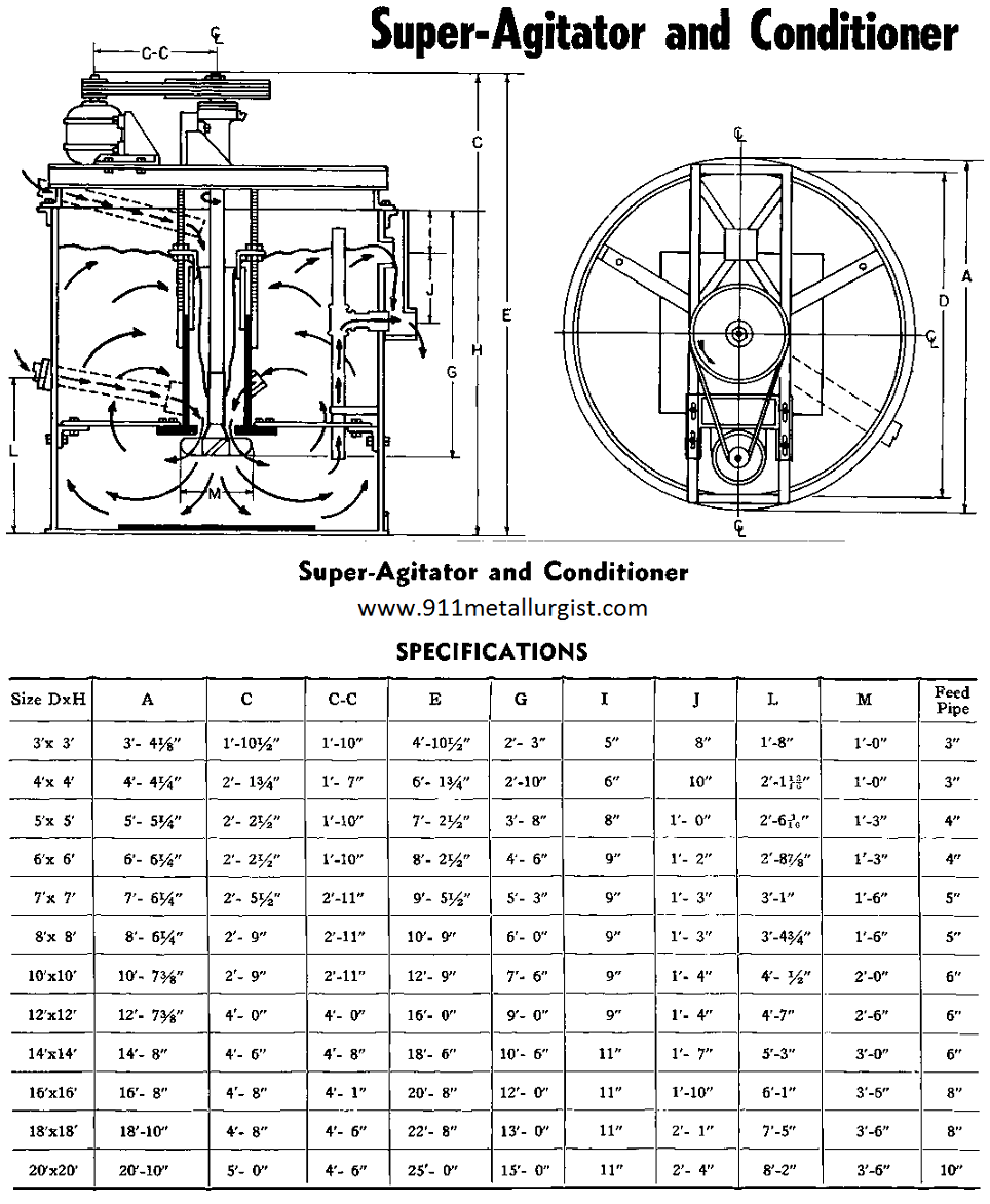
The Super-Agitator and Conditioner is a heavy duty machine. It is specifically designed for handling pulps of high density and coarse high specific gravity solids. The mechanism is supported on a beam type superstructure which may be mounted on an open or closed tank of wood, steel, concrete or other suitable material.
The enclosed bearing assembly includes a heavy duty thrust bearing at the top to support the weight of the mechanism. The lower bearing is a self aligning type adequately protected with grease seals to prevent the entrance of foreign material.
Intense Agitation Without Excessive Speed or Horsepower
The speed of the propeller is relatively slow and is determined in terms of peripheral speed. The average peripheral speed is calculated at about 1400 feet per minute. Thus, the r.p.m. decreases as the size of the propeller increases.
Standpipe
The most important feature of the Super-Agitator and Conditioner is the central standpipe. This standpipe is suspended from the superstructure and properly braced to hold it rigidly in place. At the lower end of the standpipe is a wearing plate approximately the same diameter as the propeller. This wearing plate controls the flow of pulp and is an important factor in reducing the horsepower of this unit, as it limits the amount of pulp agitated by the propeller to that which flows down the standpipe.
The upper end of the standpipe is equipped with an adjustable collar which is the operating control of this unit.
Aeration Control
When the adjustable collar is raised to maximum height, there is no flow of pulp down the standpipe. Under these conditions, the amount of aeration is limited and the vertical circulation in the tank is also at a minimum. As the collar of the standpipe is lowered an increasing volume of pulp flows down the standpipe until a vortex is formed around the shaft. In this range, aeration is at a maximum. As the collar is lowered still further, circulation increases but aeration decreases, until the standpipe is completely flooded and aeration ceases altogether.
There are also inlets at various heights on the standpipe to allow the re-circulation of pulp from intermediate points. The arrangement gives the operator positive control over the conditions to be obtained in the machine.
Air-lift Agitator
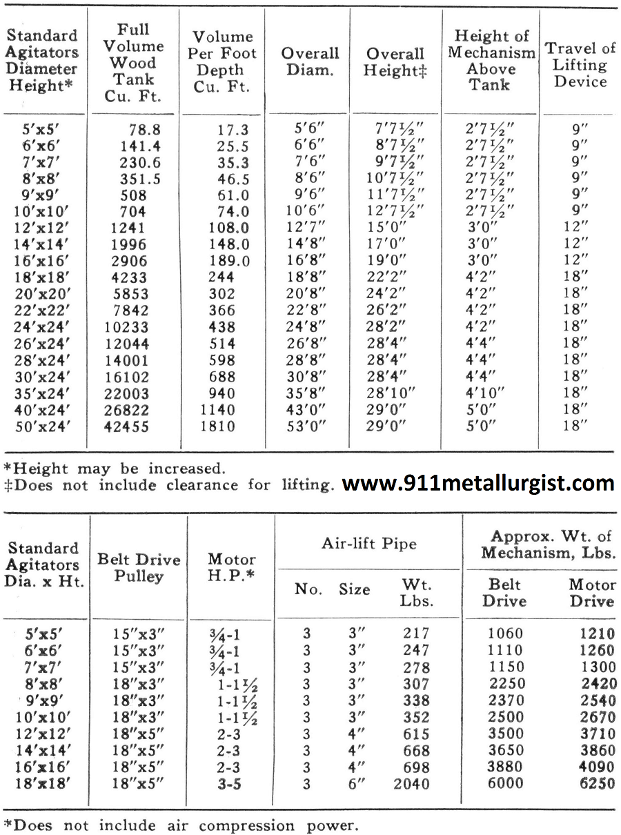
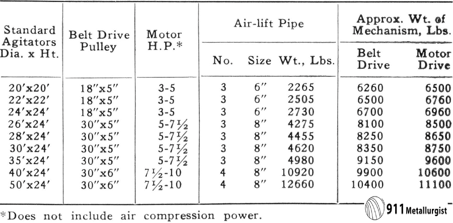
Air-lift Agitator has a wide application in mining and industrial plants to agitate, aerate and condition any finely divided material with a liquid. It maintains a uniform density or mixture with minimum horsepower. A positive handwheel operated lifting device allows the rakes to be raised out of settled solids during a shut down and then lowered after operation is resumed. It is important to note that this hand-wheel is conveniently located on top of the drive mechanism and is therefore readily accessible.
The totally enclosed worm gear drive, effectively sealed against the entrance of dust and dirt, gives the high ratio of speed reduction necessary for this type of agitator. High- grade gears and ball and roller bearings operate in a bath of oil which assures proper lubrication and the liberal use of anti-friction bearings is partially responsible for the low power requirements of the Air-lift Agitator.
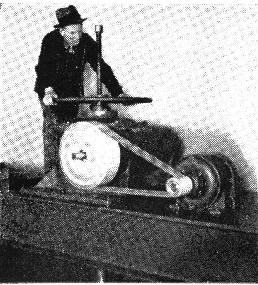 Air-lift Agitator Showing Totally Enclosed Worm Gear Drive
Inasmuch as the air-lifts are located at the periphery of the tank, use is made of centrifugal force in conveying the heavy settled solids to the air-lift. This is another factor responsible for low power consumption. Three side air-lifts are standard. However, for unusual conditions additional air-lifts may be installed. Center air-lifts can also be used on these agitators with reduction in speed and horsepower.
(Patented) Super-Agitator and Conditioner mechanisms may be added in any number to give intense agitation, or where froth is to be broken down, with the least possible horsepower increase.
Additional data gladly furnished upon request.
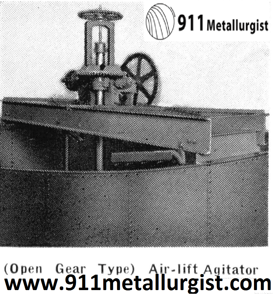
AGITATOR, (Open Gear Type) Center and Side Air-lift
The (Open Gear Type) Air-lift Agitator is of the low-head beam type construction, with either side or center air-lifts. Distributing launders may be mounted at the periphery of the tank, or on the rotating central stirring shaft. This agitator is economical to purchase and is preferred by many operators where initial cost is a main factor. Extra aeration and agitation can be obtained by an auxiliary Super-Agitator mechanism. The (Open Gear Type) Air-lift Agitator is available in the same sizes as the standard air¬lift agitators which have totally enclosed worm gear drives. Additional data gladly furnished upon request.
FLOTATION AGITATOR AND CONDITIONER (Open Type)
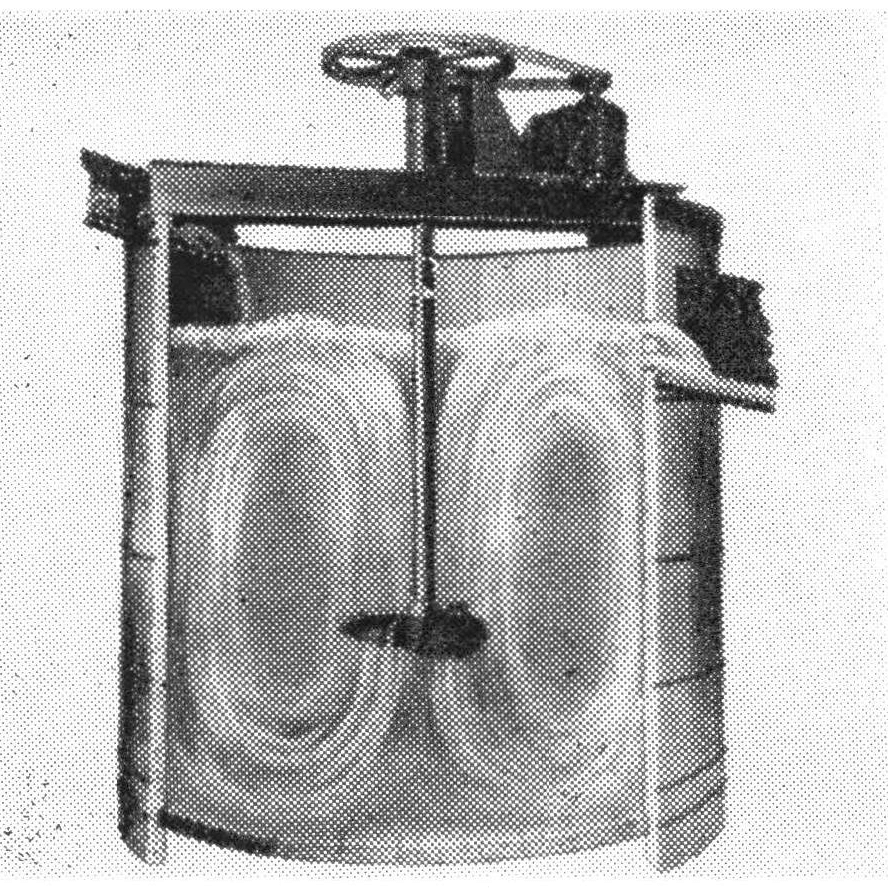 (Open Type) Agitator and Conditioner Showing Pulp Circulation
(Open Type) Agitator and Conditioner is similar to the (Patented) Super-Agitator and Conditioner except that the hood and standpipe have been eliminated. This unit can be successfully used where conditions require a moderate agitation or mixing action on light pulps. Many industrial applications where continuous mixing is required utilize this sturdy but economical agitator. Further detailed data on dimensions and capacities and other valuable information can be obtained by writing any Equipment Company office.
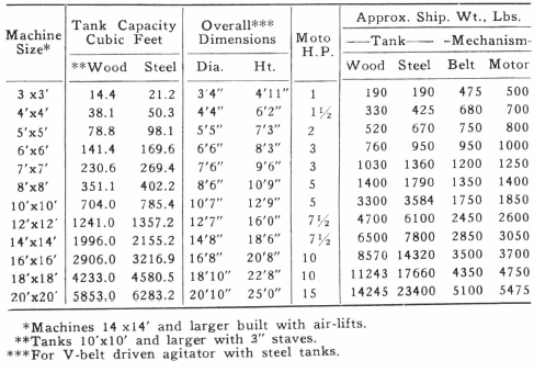
FLOTATION AGITATOR AND CONDITIONER
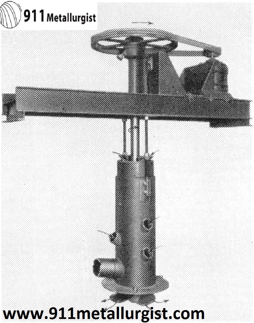
(Patented) Super-Agitator and Conditioner is especially designed for intense agitation and aeration. It has a wide application as a conditioner, an agitator, a mixer, or an aerator. It will handle any pulp or slurry, or combination of liquids or solids, that will flow through a ten mesh screen.
The (Patented) Super-Agitator and Conditioner is a heavy duty machine. The mechanism is supported on a beam type superstructure which may be mounted on an open or closed tank of wood, steel, concrete, or other suitable material. The enclosed anti-friction bearing assembly carries the heavy duty shaft and three blade ship type propeller, which may be furnished of cast iron, rubber, or special alloys as required. Recirculation of pulp is controlled by an adjustable collar on the
standpipe, and by recirculation holes in the standpipe itself. In large tanks auxiliary air-lift pipes are supplied to increase circulation and aid aeration.
The (Patented) Super-Agitator and Conditioner can be easily started after a shutdown, and accordingly is valuable for batch work. Short circuiting of pulp when used continuously is prevented by positive feed to propeller. Additional data gladly furnished upon request.
Flotation Conditioners
Flotation Conditioning Tanks are used because reagents can generally be added at various points in the grinding circuit for the treatment of straightforward ores, but selective flotation often requires a more accurately controlled period of contact. For this purpose a conditioning tank, of which a useful type is illustrated in Fig. 31, is placed in the circuit immediately ahead of the flotation section that it is designed to serve.
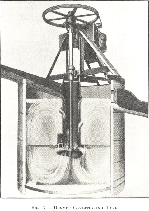
Incoming pulp enters the top of the open stand-pipe and falls on to the propeller, which is set to force it downwards and outwards, this arrangement insuring a positive circulation during the conditioning period. A stationary hood is fitted to the bottom of the stand-pipe immediately above the propeller ; this not only prevents the latter from becoming choked in the event of a shut-down but also assists materially in reducing the power consumption. The outlet for the discharge of the pulp is situated at the side of the tank at a level calculated to give the correct time of contact of the reagents with the pulp. A series of holes, one above the other, allows this period to be varied if necessary.
The operation being continuous, at first sight it would seem as though a particle of ore might easily be swept straight through the tank without undergoing its proper period of conditioning. In practice no short-circuiting of this sort is found to take place, as long as some device such as that of the stand-pipe over the propeller is provided to insure positive circulation.
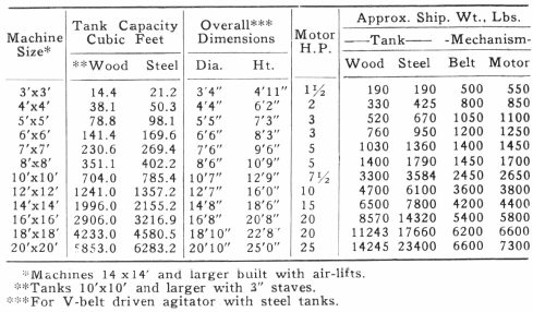
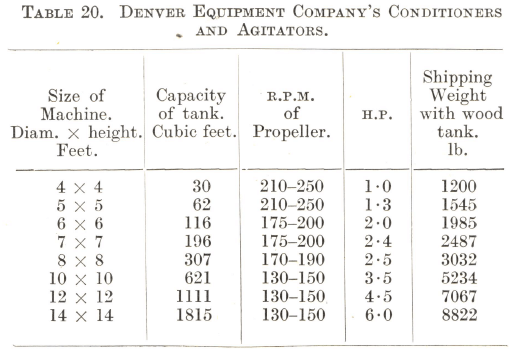
The sizes, capacities, and power requirements of the Denver Conditioning Tank illustrated are given in Table 20.
Source: This article is a reproduction of an excerpt of “In the Public Domain” documents held in 911Metallurgy Corp’s private library.

