Steady-State Pit Dewatering Simulations: Steady-state simulations of the observed potentiometric surface of the aquifer were used to calibrate the model. Calibration is the procedure by which initial input parameter values are adjusted to produce a more accurate simulation of the observed potentiometric surface. Initially, the field values of hydraulic conductivity, aquifer recharge, streambed permeability, and hydraulic head were used in these simulations. Values of streambed permeability, hydraulic conductivity, aquifer anisotropy, and aquifer thickness were adjusted within the range of established field data during the calibration procedure. Figure 7B shows the simulated potentiometric surface of the aquifer and was produced by using the adjusted input parameter values.
Deep-Well Dewatering Schemes: The ability of the numerical model to simulate the effect of one or more pumping wells was used to simulate the effectiveness of various deep-well dewatering schemes. In each of these schemes, one or more pumping wells were used, and the effectiveness of each scheme in lowering the potentiometric surface of the Llewellyn-Pottsville-upper Mauch Chunk aquifer was observed. This was done by assigning pumping wells to specific nodes and changing the number, configuration, and pumping rate of the wells. Consequently, it is possible to design a deep-well dewatering scheme using the numerical model that maximizes the amount of well interference and, therefore, drawdown while minimizing the number of wells. It also is possible to simulate the effects of changing pumping and recharge rates, and well breakdown.
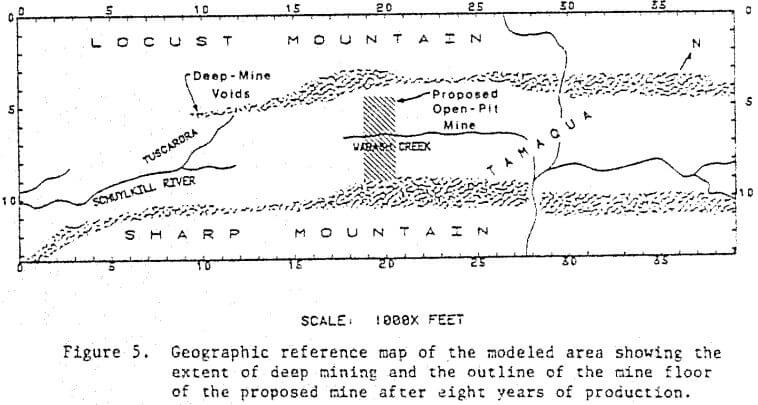
Figure 10A shows the potentiometric surface produced from pumping two wells at 250 l/s (4000 gpm) each. These wells were located in mine pools located in the deep-mine voids on the north and south flanks of the valley. The formation of a cone of depression around each pumping well shows that most of the water in the mine pools is dewatered. However, it is important to notice that neither of the cones of depression is sufficiently wide to dewater the central part of the valley where the proposed mine will be located. This is due to the permeability difference between the unmined, relatively impermeable valley core and the mined, extremely permeable valley flanks. As a result of this extreme anisotropy, the cones of depression have an elliptical shape, elongated in the direction of greatest permeability, along the orientation of the deep-mine voids. The simulation shows that this dewatering scheme would be ineffective because even after eight years of pumping, hydraulic head values of 900 feet or more exist in the central part of the valley where the proposed mine is to be located.
Differences between simulated and observed hydraulic heads ranged between 0 and 42 feet. The largest differences were on the ridge crests and the valley bottom where observed hydraulic head data were meager.
Comparison of Figures 7A and 7B shows that the model did simulate the major hydrologic features of the ground-water flow system in the modeled area: the ground-water mounds beneath Locust Mountain and Sharp Mountain, the bend of the 900-foot equipotential line into the deep-mine voids on the south side of the valley, and the flatter hydraulic gradients in the deep-mined areas. Simulations also were made to check the sensitivity of various input parameters, see Bair (1980).
Transient Simulations: Transient simulations were made to evaluate the hydrologic effects of the first eight years of mining. Input parameter values for these simulations included the adjusted values from the steady-state simulations, the simulated hydraulic head values, and a specific yield value of 0.005. Transient simulations also were made using specific yield values of 0.05 and 0.0005. Differences in the simulations caused by these changes in the value of specific yield were negligible.
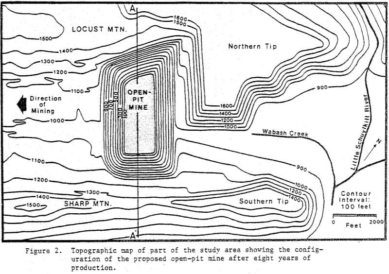
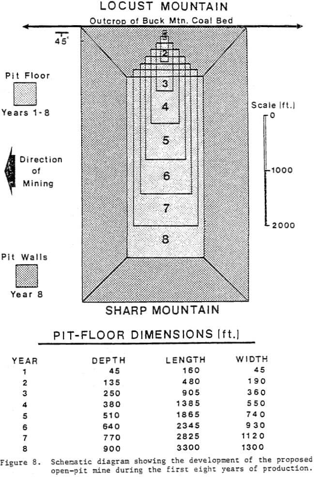
The transient simulations were designed to permit the configuration of the proposed mine to change in one-year increments. Thus, a record of the response of the flow system to the progressive development of the mine was obtained at the end of every year for the first eight years of mining, prior to pit advancement upvalley. Figures 9A, 9B, 9C, and 9D show the simulated potentiometric surface after 2, 4, 6, and 8 years of mining, respectively. The “X” on each map represents the center of the proposed mine.
These maps display several interesting hydrologic features.
In Figure 9A, the mine is represented by one constant-head node having a hydraulic head of 815 feet. The 900-foot equipotential line in this figure shows the initial development of a cone of depression around the mine.
The mine in Figure 9B is represented by eight constant-head nodes, each having a hydraulic head of 570 feet. At this time, the mine is still rather small and has not extended very far across the valley, see Figure 8. Figure 9B shows that the spreading rate of the cone of depression is much greater upvalley than it is across valley. This is what would be expected to occur along the flank of Locust Mountain where there has been extensive deep mining, see Figure 5.
In Figure 9C, the mine is represented by 32 constant-head nodes, each having a hydraulic head of 310 feet. At this time, the mine is considerably larger and extends nearly halfway across the valley but has not yet intersected the deep-mine voids on the south flank of the valley, see Figures 5 and 8. Figure 11C shows that the cone of depression is still spreading more rapidly along the north flank of the valley in the unmined, less permeable core of the , valley.
In Figure 9D, the mine is represented by 70 constant-head nodes, each having a hydraulic head of 50 feet. At this time, the pit has reached its maximum size and extends across the entire valley, intersecting the deep-mine voids along the flank of Sharp Mountain. The hour-glass shape of the cone of depression is the result of the extreme contrast in permeability between the poorly permeable core of the valley and the highly permeable flanks of the valley. The steepening of the hydraulic gradient in the waist of the hourglass shape indicates the lower permeability of the core of the valley. The flatter hydraulic gradients along the flanks of the valley indicate the higher permeability of the deep-mined areas. The cone of depression at this time is approximately 4900-m (20 000-ft) long, 1600-m (8000-ft) wide, and 300-m (1000-ft) deep. Water levels on Locust Mountain and Sharp Mountain in the vicinity of the mine dropped between 15 to 55 m (15 to 80 ft). Water levels in the remainder of the modeled area are unaffected by the proposed mining operation.
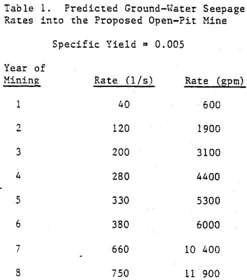
Ground-Water Seepage: Ground-water seepage into the pit was determined at the end of each year for the eight-year simulation period. Table 1 lists the ground-water seepage rate data from the transient simulation made with the previously stated input parameter values and a specific yield of 0.005. As would be anticipated, the rate of ground-water seepage into the mine increases as the mine dimensions increase. However, the changes in the rate of increase reveal some interesting features about the effect of the local ground-water flow system on the rate of ground-water seepage. During the first five years of mining, the rate of increase of the seepage rate increases at a fairly uniform rate. But, in the sixth year of mining, the rate of increase decreases. This is probably due to the location of the mine within the valley. Prior to the sixth year of mining, the mine is enlarging within the highly permeable deep-mined area on the north side of the valley. However, during the sixth year of mining, the mine enlarges to its greatest extent within the relatively impermeable central core of the valley. In response to the low permeability of the central core of the valley, the rate of increase of the seepage rate decreases. During the seventh year of mining, the mine extends further toward Sharp Mountain and breaches the mine voids along the south side of the valley, which causes the large increase in the seepage rate during that time period. The rate of increase in the seepage rate decreases during the eighth year of mining as the mine voids on the south side of the valley dewater.
Surface Drainwells
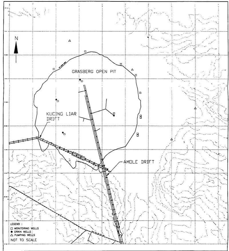
The second method for removing ground water from the Poker Chip, is drilling and completing a network of surface medium diameter drainwells. These wells are drilled and constructed essentially in the same manner as pumping wells but instead of installing a pump and removing the water by pumping, the drainwells are drilled to the 9,690 foot elevation level. At this elevation the water is drained to a collection chamber, from there the water is conveyed to the Amole Drift system. The drainwells are connected by single drifts which are driven from either side of the Amole drift.
The positioning of the drainwells are determined by utilizing a stratagraphic contour map which was developed to show the approximate bottom of the Poker Chip. After initially proposing a location of the drainwell, a small-drill rig is brought to the location, and a small diameter (nominal 4-inches) borehole is drilled to a depth approximately 660 feet below the intercepted water table. Upon completing the borehole, a nominal two-inch, slotted and blank, PVC pipe is installed to total depth and a cement surface seal is installed. The geologic and water level information which is collected during the completion of the monitoring well at each location has provided essential data for the bigger drill rig which is then brought onsite for the drilling of the drainwell.
The preliminary surface drainwell plan involved drilling and constructing approximately 10 drainwells. To-date, due to the success of the underground drainhole program, it is anticipated that as few as four or five surface drainwells will be required to drain the ground water from the Poker Chip and provide pit slope wall stability. The drainwells are constructed in areas where the Poker Chip has the greatest potential saturated thickness, and where the underground drainholes cannot reach the Poker Chip due to the upgradient distance. A diagram showing the locations of the surface drainwells is below. This diagram also shows the locations of the monitoring well network and the proposed locations of the interceptor wells.
During the drilling of the first drainwell, numerous drilling problems were encountered which resulted in the drill bit and stabilizers becoming stuck. The borehole had to be abandoned after the bit and stabilizers were shot off and the drill pipe removed. Learning from the problems and drilling conditions which were encountered at the first drainwell site, the following drilling and construction schedule was undertaken. A diagram of the drainwell’s construction is shown on the following page.
A nominal 34-inch surface borehole was drilled to a depth of 55 meters, then nominal 30-inch blank steel, conductor casing is installed to total depth and cemented into place. This portion of the borehole is drilled using the direct mud-rotary drilling method. A nominal 28-inch borehole is then drilled to a depth of approximately 65 feet below the water table. This portion and the remaining portions to total depth of the borehole, are drilled utilizing the fluid reverse drilling method. Within the Grasberg Pit, the water level has been determined to be at an approximate elevation of 12,200 feet. After the borehole is drilled to its determined depth, 24-inch stainless steel, blank steel casing is installed and the annular space is at the bottom and at ground surface. A nominal 17 ½-inch borehole is then drilled to a depth which is approximately 65 feet above the drift which conveys the drain water to the main Amole Drift. If during the drilling of the nominal 17 ½-inch borehole, downhole drilling conditions may require a reduction of the borehole size. If this is the case nominal 15-inch stainless steel, blank casing is installed. After installation of the casing, a nominal 14-inch borehole is drilled to a total depth of 65 feet above the drift.
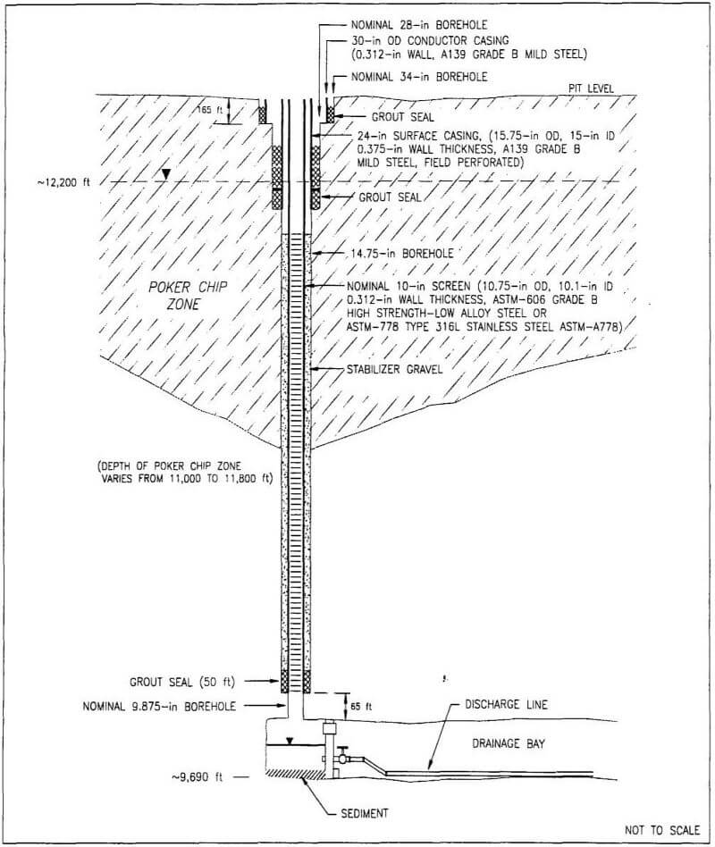
After drilling the borehole to a depth which is 65 feet above the drift, the borehole was surveyed using a gyroscope logging tool. This helps determine the boreholes bottom position in relation to the drift. The drift which has been constructed to a distance of approximately 30 meters from the boreholes bottom position, is then driven to a position underneath the borehole. A water collection chamber is then constructed within the drift, utilizing a concrete bulkhead. The bulkhead has pressure relief valves, three 10-inch water flow valves, and a large diameter sediment valve, which allows material to be flushed from the chamber. The bulkhead is constructed to ensure the ability to control the flow of water in case the water has to be shut off.
Because maximum water production is required, the entire reach between the water table or the bottom of the 15-inch casing to total depth is screened. The casing installed in this reach is a nominal 10-inch stainless steel, Rosco-Moss louvered screen, with 100 slot openings. Following the installation of the 10-inch casing, a cement plug is then placed in the bottom 10 to 15 meters of the borehole. A gravel pack utilizing ¼-inch x 3/8-inch gravel is then installed in the annular space to maintain borehole stability. After the collection chamber has been constructed underneath the proposed break through point of the well, a nominal 10-inch borehole is drilled for the final 65 feet until break through to the chamber is completed. Water from the drainwell is then conveyed through the bulkhead and into the main Amole Drift system. From there the water is conveyed via a pipeline distribution system to be used within the mill operation.
Total drilling depths of the drainwells range from 2,800 feet to greater than 3,100 feet. It is anticipated through preliminary results of the regional ground water model, that these wells will yield 2,000 to 3,000 gpm over an extended period of time of approximately two to three years. In combination with the underground drainholes, the surface drainwells are providing a means for draining the Poker Chip and providing pit slope stability.
 |
 |
