Table of Contents
The pumping of solids in water suspension is an important part of many metallurgical and mining operations. In most cases, it is still in the rule of thumb category for which no universal formula has been developed, and much research is needed.
Pumping Florida Pebble Matrix
Pumping at the Noralyn mine of International Minerals and Chemical Corp. will be used as an example. Other areas will vary as to the characteristics of the matrix, especially the slime content.
A typical screen analysis of this matrix is: +14 mesh, pebble size, 2.1 pct; —14 +35 mesh, 11.4 pct; -35 +150 mesh, 60.5 pct; -150 mesh, 25.0; total, 100 pct; moisture in bank, 20.0 pct; weight per cu ft in bank, 120 lb.
The —150 mesh fraction may increase to as much as 35 pct in adjacent areas.
A typical pulp handled is: total volume, 7800 gpm; water, 4500; solids pumped per hr, 4200 lb; sp gr pulp, 1.4; percent solids in pulp, 46.; pipe size, 16-in. ID; pulp velocity, 12.85 fps; probable critical velocity, 10 fps, as below this minimum velocity choke-ups would be numerous.
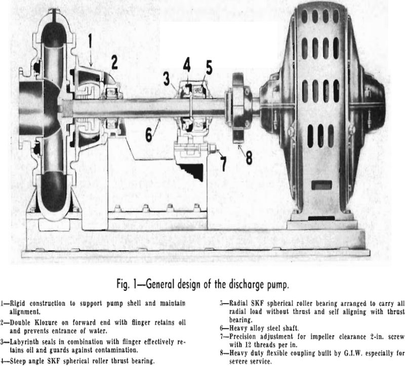
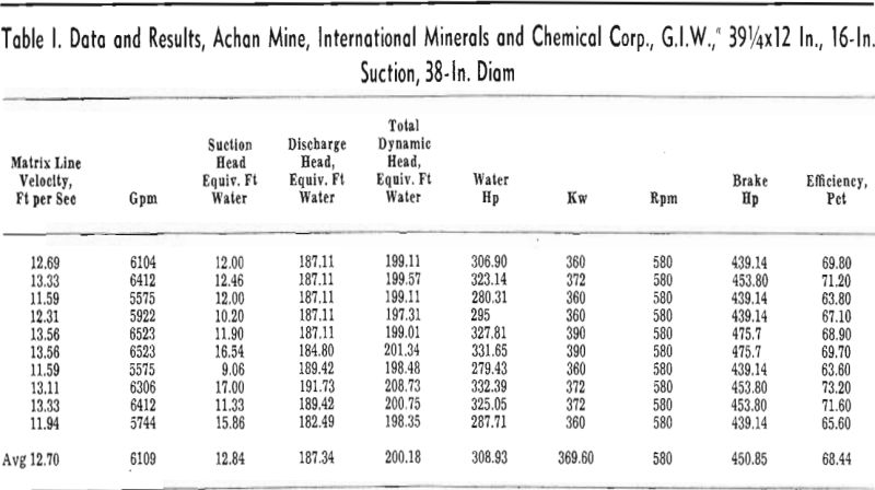
Pumping Tennessee Matrix
The Tennessee Valley Authority built and operated a 3-mile pipeline between the Akin mine and the Godwin beneficiation plant, in Maury County, after a thorough study of various forms of transportation. Because of the terrain and operating requirements, pipeline transportation has proved the most economical and has furnished valuable hydraulic data.
The matrix, consisting of a conglomerate mass of clay, silica, and phosphate particles, is mined from open pits by draglines at the rate of 70 to 90 tons per hr.
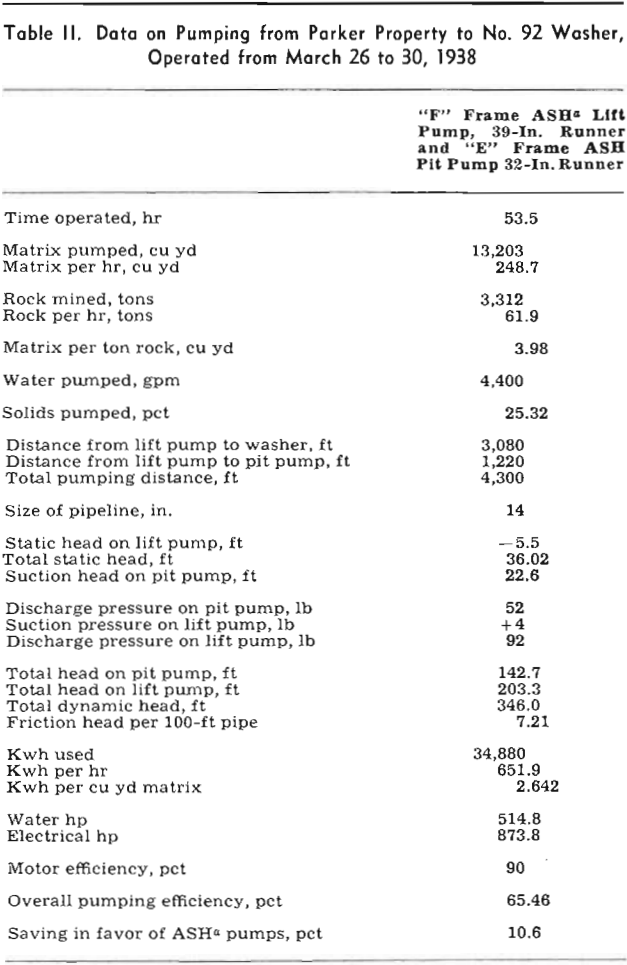
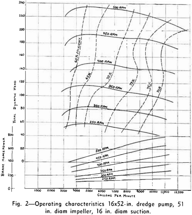
Hydraulic Transportation System
In general the design problem presented by the requirements of the flowsheet of the beneficiation
plant was to provide a hydraulic transportation system consisting of pumping equipment and accessories and a pipeline approximately 16,000 ft long for transporting up to 90 tons per hr of concentrate, as a water slurry or pulp, from the Akin plant to the Godwin plant.
Theoretical Considerations
Previous investigators have reported that two types of flow exist for slurries or pulps similar to the laminar and turbulent states of flow which are characteristic of true liquids. Also, it has been found that Poiseulles’ equation for viscosity does not apply to laminar flow of slurries as it does for true liquids, although it does apply to both type fluids in the turbulent flow range, and in this range the viscosity of the slurry is the same as that of the liquid in which the solids are suspended. It has been found that with slurries, laminar flow changes to turbulent flow at a rather clearly defined velocity, referred to as the critical velocity, and that this velocity depends on the solids content of the slurry and the particle size distribution of the solids.
Although the mechanism of transporting slurries in pipelines had been investigated considerably in small scale tests, with limited verification by data on dredging operations, most of the information reported involved material dissimilar to phosphate
concentrates, and it was not believed that these data were adequate for the design of TVA’s transportation pipeline. Therefore, to study more thoroughly the effect of slurry properties on transporting characteristics and to provide data for design purposes, an experimental program was carried out on pumping phosphate slurries containing from 2 to 35 pct solids through 400 ft of 2 and 4-in. diam iron pipe at velocities of from 7 to 11 fps. These velocities were found to be above the critical velocity for this system; below a velocity of about 7 fps the solids tended to settle out and resulted in stoppage of the pipelines.
Hω = (V)/(1.318 CRO.63) 1.85
Where: Hω = friction loss, in feet of water per foot of pipe length; V = velocity, in feet per second; C = constant, varying with the kind of pipe and the conditions of the wall; and R = the hydraulic radius.

Pipeline Location
After the size of the pipe diameter had been determined, it was necessary to make a detailed study of the location of the line and to determine the total head, select and locate the pumping equipment in the system, provide facilities to insure continuous operation, and incorporate certain features considered necessary for safe operation of the line.
From study of several preliminary locations, the final location shown in Fig. 6 was selected because it appeared to be the most practical route between the Akin and Godwin plants when consideration was given to distance, topography, and construction costs.
The line as originally installed was an 8-in., wire-wound, wood-stave pipe. Several test sections of cast-iron pipe lined with wood staves and sections of abrasion-resistant, spiral-welded, steel pipe were included in the line. After several months’ operation, examination of the line revealed that the unlined steel pipe was withstanding the abrasive action of the phosphate sands better than the wood pipe, and experience has shown that maintenance of the wood pipe was high because of a leakage which required frequent detailed examination of the line.
Pumps Nos. 1 and 2 are located at the Akin plant near the hydroseparator, and pump No. 3 is located on the line at station 54 + 00. All three pumps are 6-in., centrifugal, closed impeller sand pumps, and at a speed of 1200 rpm develop 265 ft of head of a pulp of 1.20 sp gr. No. 1 pump is directly connected to a 250-hp, 1200- rpm, 2300-v synchronous motor running at a constant speed under a fairly constant load for power factor correction. Pump No. 2 is driven by a 250-hp, 2300-v, slip ring motor with speed variations from 640 to 1170 rpm and develops heads from 80 to 250 ft. No. 3 pump is also driven by a 250-hp, 2300-v, slip ring motor having speed variations from 760 to 1170 rpm and develops heads from 110 to 250 ft.
Hydraulic Transportation System
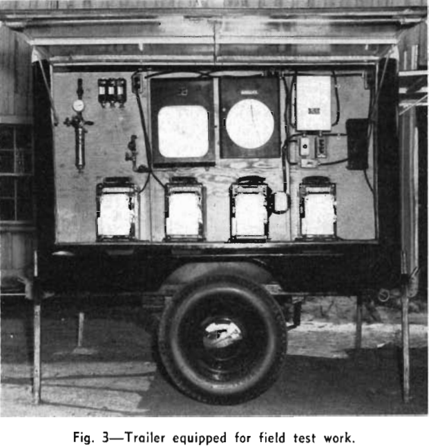
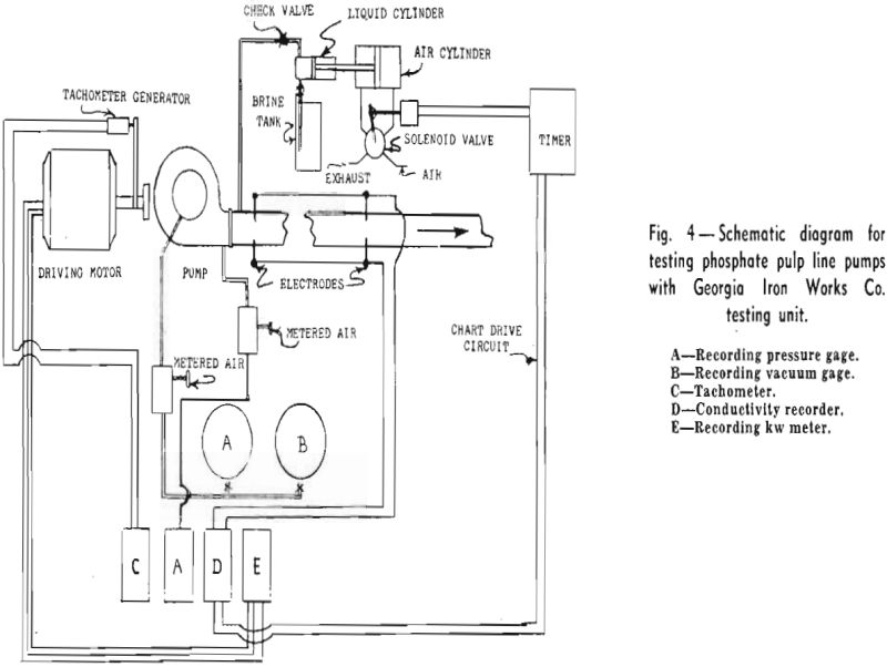
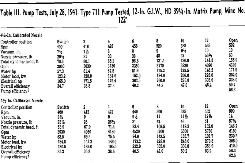
After the wood pipe had been replaced with steel pipe, a test was made of the hydraulic transportation system, while operating under normal conditions during which only pumps Nos. 1 and 2 were used. Pressure gages were installed at all the principal points in the line, recording wattmeters were connected to each of the concentrate pump motors, and the speed settings of the rheostats on the variable-speed motors were calibrated. The pulp was sampled at the discharge end of the pipeline to determine the solids content and the particle size distribution of the solids.
The pumping efficiency (theoretical, hp-hr/actual, hp-hr x 100) varied from 41 to 54 pct according to the load on the pumps, and was lowest when the solids concentration of the pulp was lowest. All of the data obtained during the test were taken with velocities above the critical point, that is, within the turbulent flow region, so that the principal variables affecting the friction losses in the pipeline were solids content, velocity, and particle size distribution of the solids.
H = 2f L/D V²/g
Where: H = head loss in feet of fluid flowing (pulp); L = feet of pipe, D = pipe diameter in feet, V = pulp velocity in feet per second, and g = acceleration due to gravity in feet per second.
The Reynolds numbers are equal to
DVP/ω
Where: D = pipe diameter in feet, V = pulp velocity in feet per second, P = pulp density in pounds per cubic foot, and ω = viscosity of water at 70°F in pounds per second-ft (ω = 6.6×10 -4 lb per second-ft). The diameter of the pipe was 2/3 ft, and the length of the pipe was 16,000 ft. All of the calculations were based on the flow from the No. 2
The experience of the Tennessee Valley Authority with the hydraulic transportation of phosphatic concentrates has demonstrated the feasibility of using this method to transport phosphates under the conditions existing in its phosphate beneficiation plant. Transportation costs have compared favorably with the costs of more conventional methods, and operation of the system is not limited by factors, such as bad weather and poor roads, which characteristically interfere with other methods, such as trucking.

