The answer to the question of how to economically move bulk materials for the industrial plant is an important facet of plant engineering. Should it be by rail, truck, tramway, water, belt conveyor, or a combination of these methods? Each system is different, and must be examined. Proximity to navigable water, terrain, availability of land, distances, life, are all important considerations.
The cross country belt conveyor is often the choice for bulk material handling. Installed cost, maintenance, reliability, simplicity, and operating expense enhance this choice. Once chosen, the design engineer is dedicated to the realization of a successful design, on schedule, and within budget. We will review with you some of the design aspects which help lead to the successful design.
Mechanical
Profile
The profile of the belt conveyor is influenced by the topography, the convex and concave vertical curves, belt tension, and idler selection. Also affecting the profile are agreements of right-of-way, crossings, and structural considerations.
The ideal profile for an overland conveyor would be a straight run of flat land allowing for the most economic selection of sections in which to sub-divide the belt system. Unfortunately, this is very seldom the case, and complicates the selection of sections that would allow an economic standardization of components.
Why standardize? The overland conveyor is the most vital artery, either feeding the raw materials to a plant for processing, or delivering the processed product to a consumer. In either case, a failure of any one component can cause costly downtime. The standardization of components will not prevent the inevitable failures, but will allow a smaller inventory of components to be available for prompt replacement with a minimum of downtime.
Recommended items for standardization are the following:
- A drive station complete with motor, reducer, and couplings mounted on a common base.
- Pulley assemblies complete with pulley, shaft, and bearings.
- Belting, one roll and two splice kits, minimum.
- Idlers, carrying and return.
Sections
The number of sections dividing an overland belt conveyor are greatly influenced by the topography, standardization, and changes in direction of the right of way, and should be kept to a minimum. At every transfer point there is a potential problem of material hangups, spillage, or excessive dusting. All lengths of belt sections, selection of components and finish profile are influenced by the belt tension.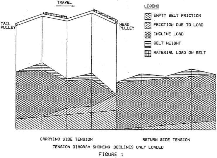
The method of loading an overland conveyor has a tremendous effect on the tension calculations. If a belt conveyor is loaded intermittently, such as a truck dump facility, there is the possibility that all of the incline segments or decline segments of the belt can be loaded at the same time. Either one of these two cases could produce the maximum tension in the belt and therefore the highest horsepower requirement, as compared to a completely loaded belt. Fig. 1 and Fig. 2 show examples of these situations. Another alternative situation is one in which a conveyor is fed from a continuous source such as a stockpile. In this case, each segment of the belt should be consecutively loaded until the belt is fully loaded. Then in the same manner, the belt should be examined for unloading the belt one segment at a time, starting with the tail, until the belt is completely empty. Fig. 3 and Fig. 4 illustrate these loading conditions. Every loading case possible must be examined. A conveyor that is fully loaded may appear to be an inclining (motoring) conveyor but when only partially loaded will be declining (regenerative). Both situations must be accounted for in the design and selection of conveyor components.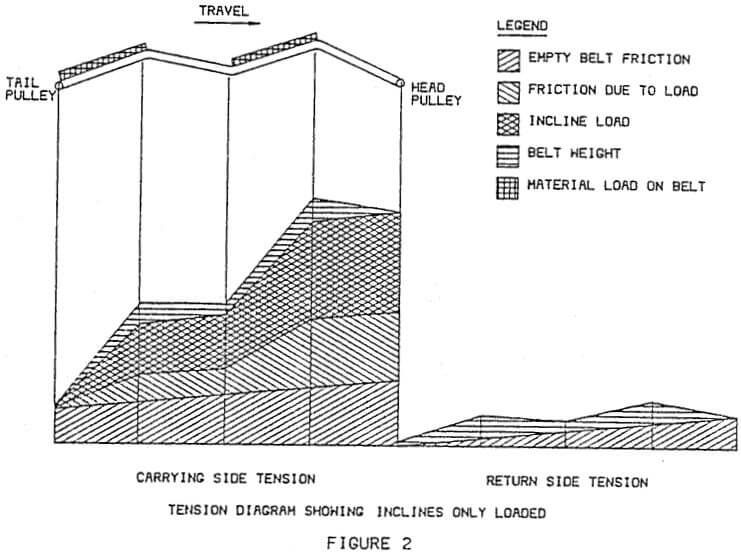
Belt tension has a direct influence on the vertical curves. The higher the tension the greater the radius of curvature. The radius of the concave vertical curve must be generous in magnitude to prevent the belt from lifting off the idlers, under all design conditions; acceleration, running, deceleration, and braking. The radius of curvature must also be large enough to prevent sagging of the belt at the edges which is caused by an increase in tension at the center fibers and a reduction in tension at the outermost fibers. Unless a belt is tremendously oversized, the liftoff calculation will be the governing factor in most designs.
The convex vertical curve must be large enough to prevent excessive belt tension in the outer fibers, thereby overstressing the belt. It must be large enough to prevent low tension in the center of the belt, which will cause the belt to buckle and result in spillage. The curve must also be large enough to prevent excessive forces on the idlers. This should be examined for both carrying and return idlers. The carrying side idlers receive the greater forces caused by material and belt load on the idlers, and in addition to the higher tensions, they have a much shorter span, plus six or more bearings in which to distribute the load, whereas the return idlers have as few as two bearings with a shaft span greater than the belt width.
The formulas for calculation of the tensions in a vertical curve can be found in a CEMA (Conveyor Equipment Manufacturers Association) publication or many of the high tension belt suppliers, and engineering literature.
Belting
Multiple-ply belts have been used with considerable success at many locations and were popular in the mid sixties. With an increase in technology and production of stronger synthetic fabrics, the present trend in belt thickness is toward a reduced number of plies. With an increase in capacities and longer hauling distances, the popularity for steel cable belting has increased.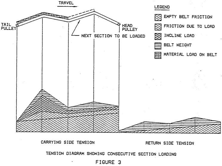
Steel cable belting uses a single-ply carcass containing a single layer of parallel steel cables, with top and bottom plies. The steel cables are the tension carrying elements of the belt. The diameter of the cables vary in size to provide the various tension requirements. The steel cable belts are used when the rated capacities of the multiple-ply belts are exceeded and should be used where take-up lengths are limited. The multiple-ply belt will stretch six times greater than the steel cable belt.
The training of a steel cable belt is much simpler than that of a fabric belt due to the parallel steel cables. The trough idlers on the carrying side keep the belt centered on the idlers due to an equalizing distribution of tension in the steel cables. To achieve this same effect on the return side it is recommended that “V” trough idlers be used. Conventional guide idlers and return training idlers have very little influence on the steel cable belt. Most of the guide idlers on current installations have been sheared off.
Takeups
The most economical location of a horizontal gravity takeup is at the tail of the belt conveyor. But on long overland conveyors the reaction time for tension effect must be taken into account. Therefore, it is desirable to nave the takeup as close to the drive pulley as possible. This will keep the minimum tension always applied to the drive pulley to prevent slippage and a possibility of fire.
As stated previously, there is a need to calculate all of the various loading conditions to establish the design parameter of the belt. There may be a situation that would dictate the need for a large takeup. If the probability of this situation occuring is remote, the counterweight can be designed for the majority of loading cases. This will increase the life of the belt conveyor components. To account for the remote condition, additional counterweight may be required and a hoist can be added to produce additional tension until the belt is running.
Pulleys
With high tension belting (steel cable belting), a special engineered class of pulley is required. Careful consideration should be given to the end disks and their hubs. The weld between the disk and hub is the area of most common failure. Stress that is inherent due to the tension of the belt, is combined with stress imposed by the compression fit of the hub. The deflection of the shaft at the hub should be limited, because it will introduce a bending moment in the hub and end disk. It should therefore be limited to a maximum deflection at the hub of .0015 radians. As you can see, the shaft must be an integral part of the conveyor pulley. The bearings should be a part of this pulley package, insuring proper fit and avoiding any field assembly errors such as two fixed or two expansion bearings on the same pulley. With the use of steel cable belt it is necessary to insure precise concentric fit and avoid rim ovality. Specifications should include a requirement limiting ovality to .013″ of the total Indicator Readout. The concentricity of the shaft and its relationship with the rim should be maintained within the same tolerance. Other imperfections in the rim can cause unusual tension in the belt, therefore, a need to machine the rim will be required.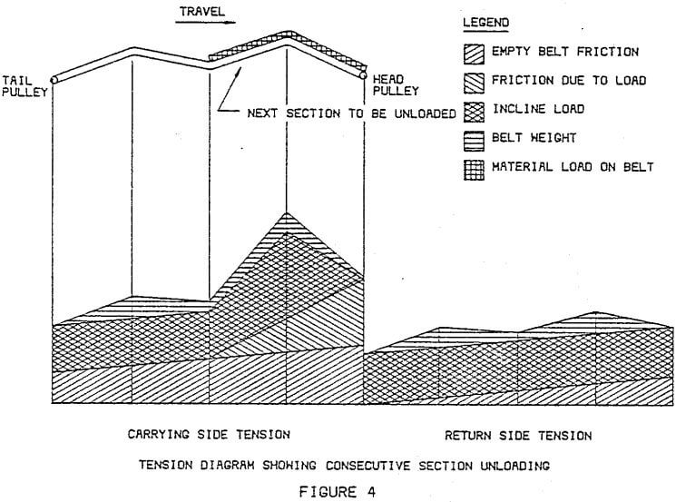
Idlers
As previously mentioned, the belt convex vertical curves are affected by the idler selection. Conversely, the idler selection can also be influenced by the curves. In a location requiring additional excavation or support structure sections, due to idler selection, it is worth investing in a higher class of idler. In addition to the load imposed by vertical curves, an idler must support the weight of the belt plus the weight of material on the carrying troughed idlers. These loads plus belt speed are required for proper idler selection.
Other distinguishing factors, besides cost, are selection of antifriction bearings and bearing seals that prevent dirt from entering the lubrication chamber. However, these differences may be reflected as different resistances influencing tension. This should be examined carefully in conjunction with different lubricants.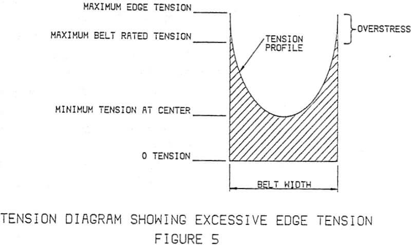
Idler spacing on the carrying side is a function of belt sag. Experience has shown that more than 3% sag will result in spillage. The calculation of sag is usually taken at the point of low tension. On most conveyors, this is at the tail end or the load point. As the tension of the belt increases, the percent of sag will decrease. It is therefore advantageous to increase the idler spacing as you approach the head or drive section of the belt. Along with increased spacings are increased loads which may be restrictive for allowable live load of the idler.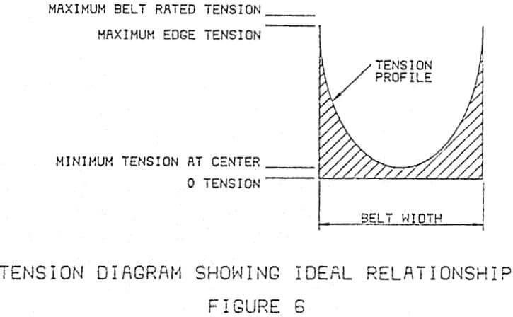
Normal spacing for return idlers are 8 ft (2.66m) to 10 ft (3.05m). Spacing can be increased if “V” return idlers are employed. This is a result of splitting the span of bearing to bearing. The “V” trough is usually 10° to 15°. As previously mentioned, this “V” trough assists the training of steel cable belts.
Turnover
Belt turnovers are used on the return side of the belt to keep the material carrying side of belting from contacting the return side idlers. This is done to prevent material buildup on the idlers and material from falling off along the length of the belt. This is achieved by turning the belt over 180° after the discharge and again turning it over prior to the tail pulley.
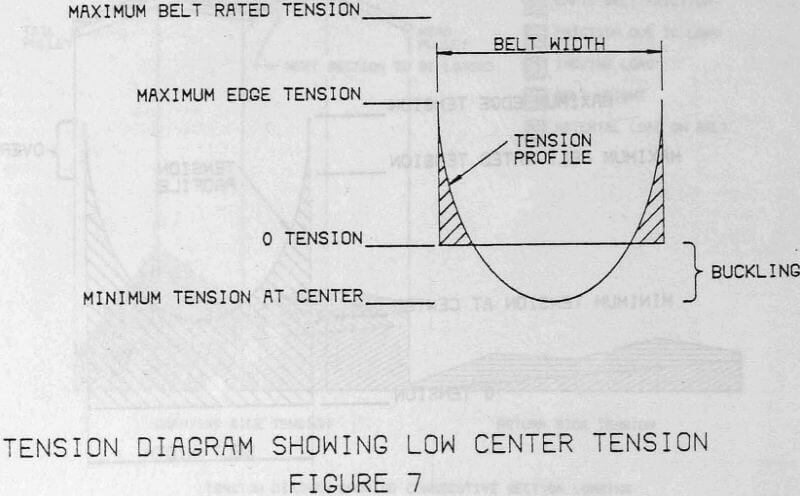
The length of the turnover is critical to the life of the belt. If the length of the turnover is not long enough there is a possibility of the belt buckling. This is caused by the edge tension-exceeding the rated tension of the belt or the tension in the center of the belt becoming minimal. Fig. 5, Fig. 6, and Fig. 7 illustrate overstress, ideal, and understress conditions. The tension distribution of the belt in the turnover is a parabola. The tension is a calculation of the elongation of the cables in helix of the turnover.
