Table of Contents
Copper smelters of various kinds have operated in the Morenci district since 1872, but all have been abandoned with the exception of the present Morenci Smelter of Phelps Dodge Corporation, which was completed in 1942.
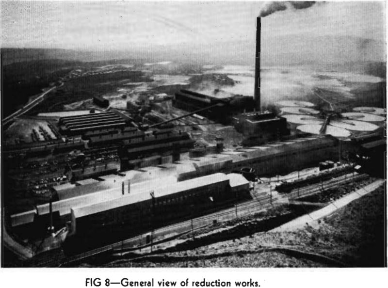
During the five-year period starting in 1937, the Morenci ore body was prepared for open pit mining, pilot mill test work was carried out, and a complete reduction works, of which the Smelter is a part, was designed and erected. Actual construction work on the Morenci Smelter was started in the fall of 1940, and warming up of the units began on April 1, 1942. Charging of the reverberatory furnaces commenced on April 18, 1942, and the first anode copper was produced on April 26, 1942.
Metallurgy
The metallurgy of direct smelting, being more or less fixed by the character of the charge, is not subject to the control available in calcine smelting. Slags may be modified by the addition of suitable fluxes, but the grade of the matte is determined almost entirely by the iron :copper ratio of the concentrate.
The direct smelting operation involves distributing the wet concentrate along the sidewalls and in the bath of a reverberatory furnace by means of some suitable feeding device and raising the temperature of the charge so that first the moisture is driven off, then the first-atom sulphur is eliminated, and finally the sulphide portion of the charge melts and runs into the bath, carrying with it the non-sulphide portion which has been partially fluxed to form a suitable slag. The fusion of the non-sulphide portion is completed by contact with the irony converter slag which is regularly being poured into the reverberatory furnace. The smelting rate of the charge is influenced by the mineralogical composition of the sulphide portion of the concentrate and by the composition and amount of the non-sulphide portion including the fluxes added.
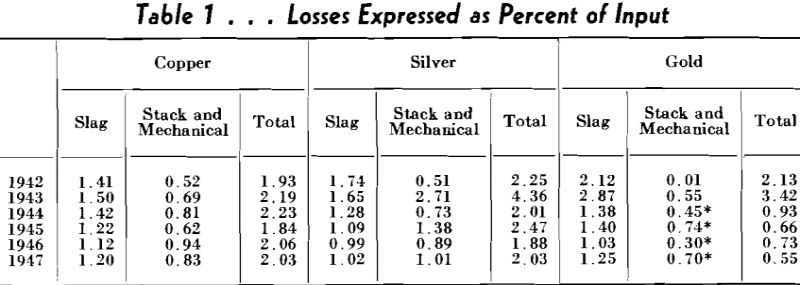
There is no metal bearing siliceous flux readily available in the Morenci district and ore from the Open Pit mining operation is too high in alumina to be used alone. It has been necessary therefore, to mine a barren quartzite for use in modifying furnace slags. This is also used in adjusting the silica:alumina ratio of the Pit ore used for converter flux to prevent the formation of excessive amounts of magnetite in converter slags. Limerock is used to flux the non-sulphide content of the concentrate, and at times, additional limerock and quartzite are added to the bedded concentrate to reduce the moisture content of the furnace feed.

Smelter Crushing Plant and Lime Burning Plant
The smelter crushing plant was designed to crush Pit ore and siliceous ore for converter flux and limerock and siliceous ore for reverberatory flux, as well as smelter reverts and miscellaneous material required in smelter operations. The crushing plant was also designed to crush limerock for a lime burning plant which is operated by the smelter organization to produce burned lime for the Concentrator.
In order to eliminate crushing of large sized material from open pit shovel mining operations, Pit ore crushed to ¾ in. is drawn from the fine ore bins at the concentrator into 40 yd side dump railroad cars and hauled to the smelter crushing plant and then conveyed to converter flux bins in the bedding plant without further crushings. Barren quartzite is mined in a quarry near the Reduction Works and trucked to the smelter crushing plant. Truck haulage is to be replaced by rail haulage at a later date. Limerock is mined in a quarry near the Open Pit Mine, trucked for a short distance, and loaded into side dump railroad cars for haulage to the smelter crushing plant.

Reverberatory Furnaces
The four direct-smelting reverberatory furnaces are located on a block of unexcavated ground 15 ft above the surrounding yard level. Furnace foundations are formed of heavy, reinforced concrete in a monolithic band around the furnace. Concrete beams were placed between the furnaces, which are on 70-ft centers, and the outer walls of the foundations on No. 1 and No. 4 furnaces were carried down¬ward an additional 8 ft to prevent bending of the longitudinal sections by expansion pressures.
After the concrete foundations for the furnaces were poured and the rods for the end steel bindings were in place slag bottoms were poured in the furnaces to seal the conglomerate subsoil and to anchor the end steel bindings. Slag for the first two furnace bottoms was melted in a small natural-gas fired reverberatory furnace located between the two furnace foundations. An abandoned reverberatory furnace at an old smelter in the district was dismantled and the brick and steel were used to build the 14 x 50 ft slag melting furnace. Crushed blast furnace slag was obtained from a slag dump from previous operations in the Morenci District and the slag was hauled to the furnace site in trucks and charged into the small furnace with a grab bucket on the boom of a motor crane. Slag was tapped in about 30-ton lots into launders leading into the furnace bottoms.
The furnaces are usually charged four or five times a shift, the charge being distributed evenly over the charge banks from both drag chains simultaneously. It is desirable to have some of the charge run out into the bath in the center channel of the furnace, thus exposing greater area to the combustion flame and to the hot bath in the furnace and providing better contact with liquid converter slag for the reduction of magnetite. If the wet charge in the bath becomes too heavy, it is forced down through the slag and comes in contact with the matte and an explosion occurs. Mild explosions are normal and are desirable because they tend to bring more of the charge in contact with the hot bath, which increases the smelting rate; but at times the explosions may be rather violent and may be hazardous to men working around openings in the furnace or boilers and may cause damage to furnace arches. It is the practice at Morenci to attempt to minimize the force of the explosions by keeping the charge banks well filled so that too much charge does not run out into the bath in one place. It is also the practice to keep tie rods tight and to use steel props on the arch to prevent movement.
A deep bath of matte is carried in the furnace at all times unless prevented by high furnace bottoms. Matte-fall is quite uniform throughout the life of each bed and amounts to 70 to 75 pct of the solid charge, or 80 to 85 pct of the concentrate smelted. Matte is tapped through either of three tap holes on each side of the furnace at the bridgewall end, opposite tap holes being used on alternate shifts to allow time for cleaning launders. The matte runs through brick and clay lined launders into 200-cu ft cast steel ladles in the Converter aisle. Two wet pan mills for the preparation of clay for stoppers and launder lining are located at the north end of the reverberatory floor.
Furnace slag is removed from the side of the furnace near the uptake end, the slag skim hole being located just back of the verb arch. The slag is skimmed into 225-cu ft cast steel pots and hauled to the dump by 18-ton electric trolley locomotives. Slagers
There are six 13- x 30-ft Pierce-Smith converters located on 60-ft centers. The converter shells are 1½ in. steel plate, welded construction with heavy reinforcing plates along the tuyere section and around the mouth. The welded steel riding rings are riveted to the shell at the outer ends of the shell. The converter ends are made of 1 in. welded plate with 4 beam stiffeners on each end and the ends are held in place by bolts and springs to allow for expansion. The springs have been of value in relieving expansion after repairs, but a point is reached where the springs cannot be used without digging out the entire end sections of the converter and re-setting the end plates in their original position.
In making copper charges, matte is blown to white metal in two converters and the white metal from one converter is then transferred to the other and the copper charge finished in that converter. Copper charges average 90 tons and the copper is blown to “worm” copper for the anode plant. Oxide slag is formed in the converter at this stage of the blow and this slag is very corrosive on the brick lining and must be handled with care to prevent explosions when it is skimmed and transferred to another converter. After each transfer or charge of copper is completed the tuyeres are reamed with a cutter bar clamped in a light rotating drill which is supported by hand. This method of reaming tuyeres is much easier on the brick work than the use of a sledge hammer and cutter bar.
Anode Plant
All Morenci copper is produced as anode copper for economy at the refinery. The anode plant is located at the north end of the converter aisle as shown in Fig 2 and contains two refining furnaces of the same type as the converters, but with shells 13 x 25 ft instead of 13 x 30 ft, and one casting wheel. Anode plant practice with rotating furnaces is entirely satisfactory and the arrangement of two refining furnaces and one casting wheel provides flexibility and storage capacity for uniform converter operations.
The anode furnace shells are made of 1½-in. plate, welded construction, with riding rings at the ends and with openings for the poling and skimming door and casting spout. The ends of the vessels are made of 1-in. welded plate with reinforcing beams which are fastened rigidly to the shell. The ends have openings for the receiving spout, burner port and stack outlet. The direct current motors and gear drives are duplicates of those used on the converters.
The anode furnaces are heated with natural gas in burners using high-pressure air for short flame combustion. The burner enters through one end wall well above the metal line. Anode charges average 175 tons of copper and two converter charges usually fill an anode furnace. The anode charges are blown with high-pressure air using two ¾-in. pipes to eliminate the sulphur, the slag is skimmed off and the copper is poled with oak or pine poles which are manipulated with an air operated hoist. The anode furnaces are surrounded by a large concrete platform at an elevation 2 ft below the center- line of the furnaces which provides working space for the blowing, skimming and poling operations.
The anodes, which weigh 700 lb, are raised from the molds by pins with sliding contact on an inclined track,s at the side of the bosh tanks. Anodes are removed from the bosh tank by a 15-ton crane, inspected and trimmed on the floor adjacent to the anode plant and are then loaded into railroad cars by 2-ton storage battery trucks with vertical lift arms. A large concrete floor across the track from the anode floor is and are lifted from the pins and placed in bosh tanks by manually operated air tongs with control valve used as a copper dock for storage of anodes during periods of interrupted shipments. This floor and the trimming floor is armored with cast iron grids cast in the concrete.
Pouring spoons are lined with a cement-sand mixture. The spoons and cast iron master molds are heated to the proper temperature for use by individual gas burners. Copper molds for the casting wheel and copper tapping plates for the reverberatory furnaces are made on day shift. The copper molds last for about 300 tons of anodes each before cracking too badly to use. One or two new molds are put on the wheel daily and the discarded molds are returned to the converters for smelting with the copper charges.
Flues and Stack
The entire flue system in the Morenci Smelter is of steel construction well insulated to prevent heat loss, and of large cross-sectional area to reduce gas velocities. Arrangement of the flue system and stack is shown in Fig 2. The steel balloon flue located back of the converters turns at right angle and rises in a vertical box connection to cross the converter aisle above the crane runway. Gases pass from this flue through mechanical dust collectors consisting of 10 sections of 16-in. Multiclone tubes, and then to the stack. The converter
flue is 18 ft in diam and is covered with 2 in. of fiber glass insulation from a point near the first converter to the dust collectors. The flue immediately back of the converters is not insulated. The mechanical dust collecting system is insulated and also the 18-ft balloon flue leading from the dust collectors to the stack.
A 15-ft steel balloon flue for reverberatory furnace gases, also insulated, leads from the waste-heat boiler outlets and joins the converter flue just in front of the portal of the stack. There is an automatic damper in the reverberatory flue which is operated by a motor
driven worm gear actuated by an electric eye connected to a draft gauge. The necessity for a dust collecting system on the reverberatory gases has not yet been determined.
