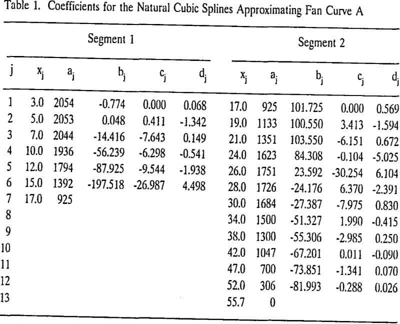
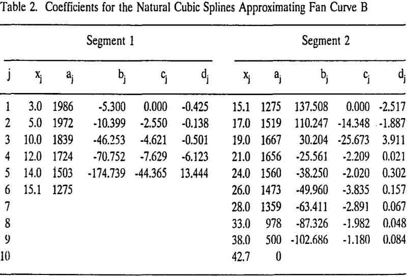
Stall or aerodynamic stall of axial-flow fans has long been recognized as an important operational problem in mine ventilation. To develop a technique for characterizing fan stall in multiple-fan ventilation networks, a research project was initiated through the Generic Mineral Technology Center for Mine Systems Design and Ground Control.
Considering that fan stall is related to multiple operating points, this paper discusses a numerical model for multiple-fan ventilation networks, design of the experimental setup for two- and three-fan ventilation networks, and numerical methods for solving multiple networks solutions. It is hoped that the results of this project will lead to an innovative method of ventilation network analysis and simulation, thus preventing stall.
Example Problems
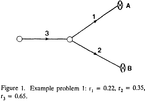
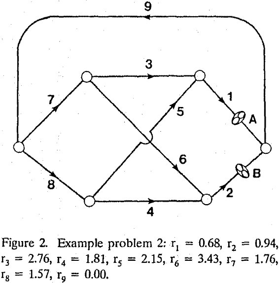
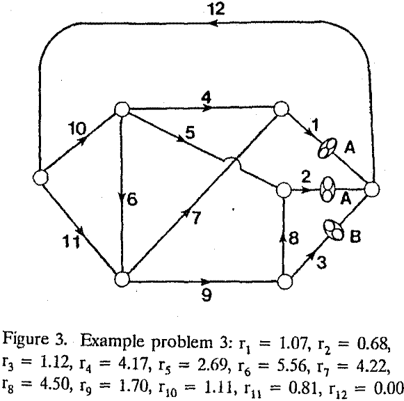
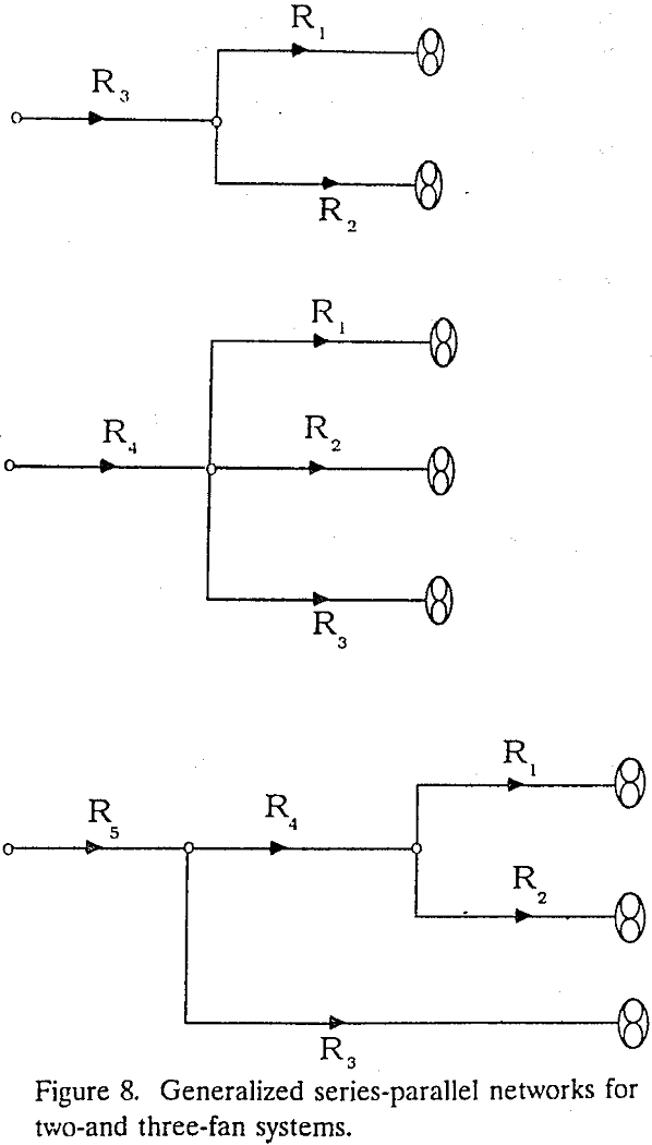
All the fans in the networks are chosen to operate as exhaust fans. Networks 1 and 2 represent two-fan systems while network 3 is a three-fan system. Letters A and B in figures and in the text represent fans A and B or the fan characteristic curves associated with the fans.
It is assumed that rj includes regulator resistances. In other words regulators are not treated separately. Booster fans and natural ventilation pressures are not included. Furthermore, the fan locations, and fan characteristic curves are also given. The unknowns to he solved here are therefore, the air quantities qj which satisfy the network equations. The type of network that meets the above conditions belongs to the “networks with natural splitting.” Specific equations applicable to network problem 1 are as follows:
h1 + h3 – p1 = 0……………………………………………….(1)
h2 + h3 – p2 = 0……………………………………………..(2)
q1 + q2 – q3 = 0……………………………………………….(3)
hj = rj qj qj j = 1, 2, 3………………………………………..(4)
where hj, pj, qj, and rj are, respectively, pressure loss, fan pressure, air quantities, and resistance factor. Eliminating q3 and hj from the above system of equations results in
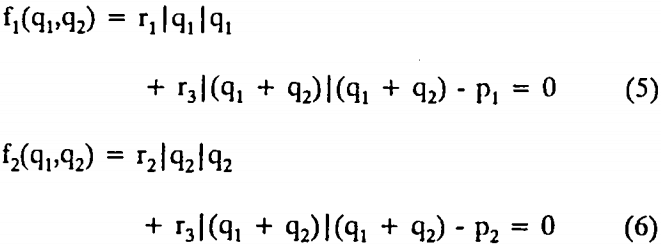
Since pressure Pj is a function of qj defined by the characteristic curve for the fan in branch j, this is a system of two nonlinear equations in two unknowns.
Experimental Setup to Simulate Fan Stall
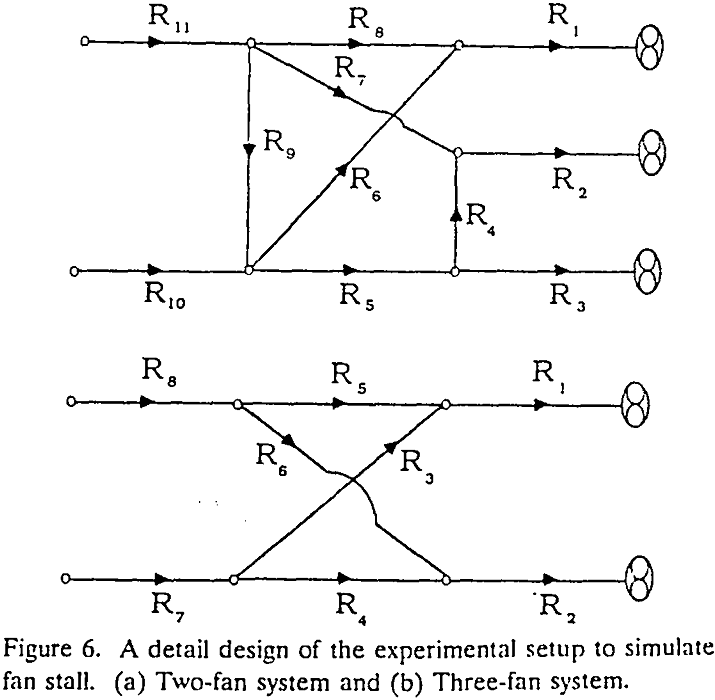
The round RIGIDUCT fiberglass tubing manufactured by Peabody ABC was chosen to construct the tubing network for simulation of stall in two-and three-fan ventilation networks. The two-fan system has eight branches with a total length of 100 ft tubing while the three-fan system has eleven branches with a total length of 145 ft tubing. Each of these branches has a graduated damper (air regulator) installed in it.
Ventilation network problems with multiple solutions are numerically constructed by a trial-and-error process based on the fan characteristic curves and properties of the tubing network. These problems are then simulated in the laboratory using the tubing network. The resistance of a branch (including the equivalent resistance of the regulator) are calculated from the measurements of head loss and air quantity of the branch. These measurements are made for each branch independent of the simulation of the network problem.
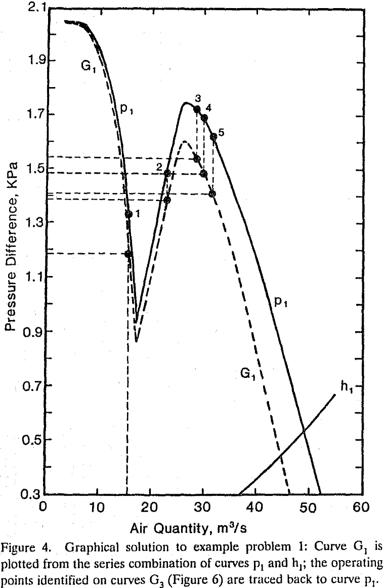
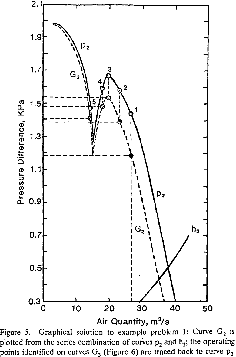
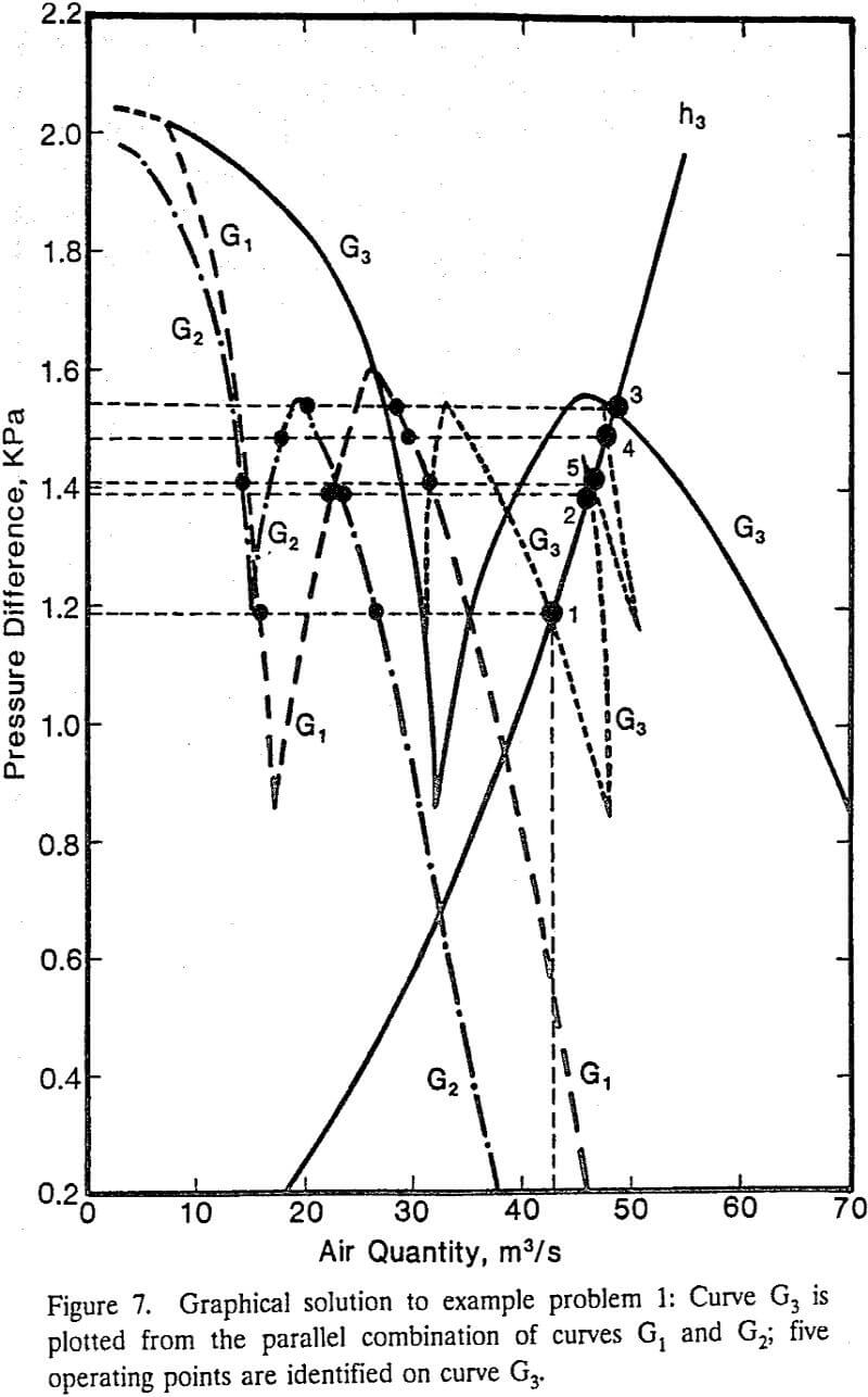
The graphical method is applicable only to the network that, “by applying the principles of series and parallel combinations, can be reduced to an equivalent system of two series branches.” In the present paper, we referred to the network with this property as the series-parallel networks.
Numerical Methods
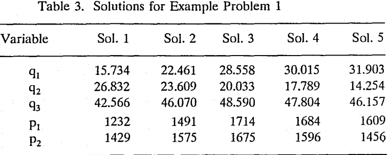
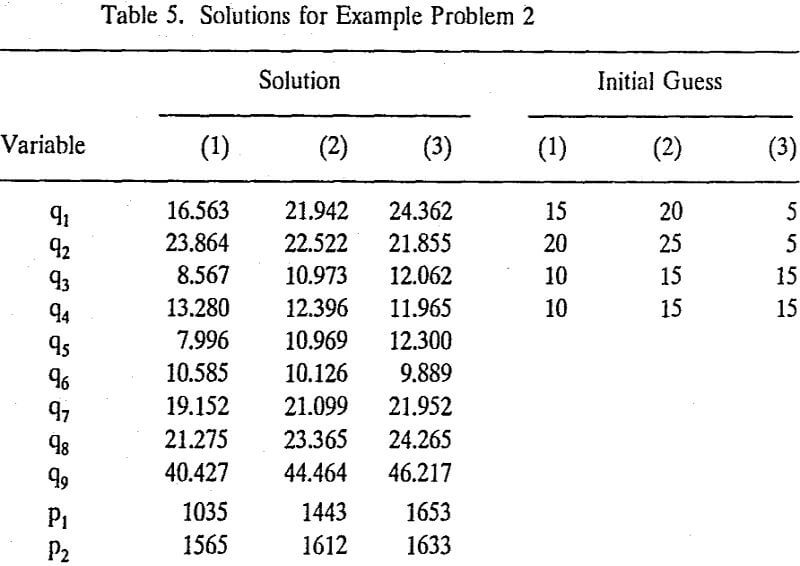
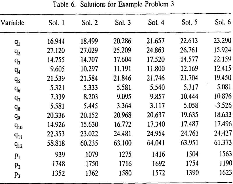
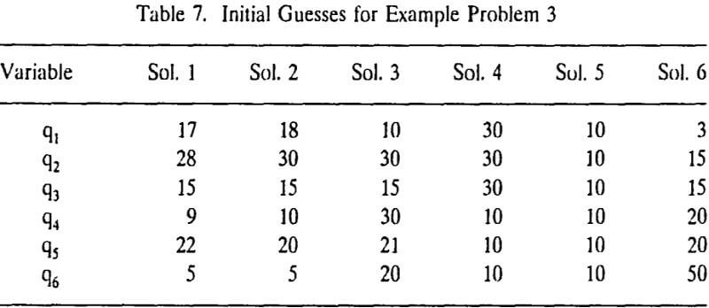
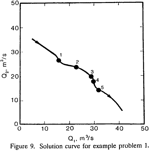
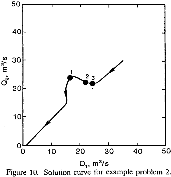
Multiple operating points may be determined by solving a system of network equations applying a numerical method with different initial guesses. In the present study, example problems 1 to 3 were solved by applying the Newton-Raphson method with different initial guesses. With a trial-and-error approach, we have found five, three, and six solutions for example problems 1, 2, and 3, respectively.
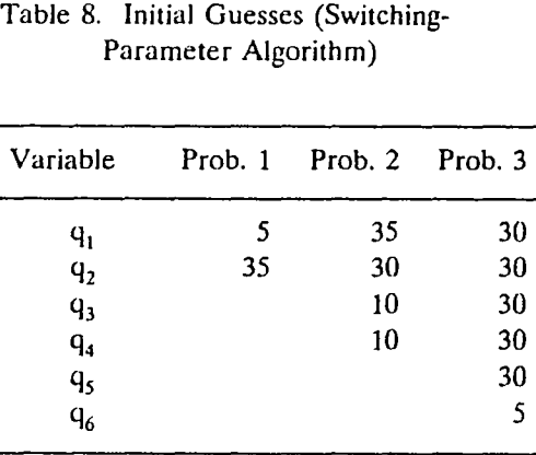
A FORTRAN program for determining the multiple solutions of the ventilation network equations has been develop based on the switching-parameter algorithm of the continuation method. “This algorithm consists of solving an associated system of first order nonlinear differential equations whose independent variable may be switched from one variable to another during each integration step”. In each integration step, the forward Euler method is used for prediction and the Newton-Raphson algorithm is then used for correction.
