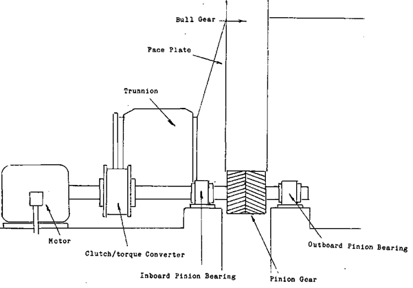
We will begin with the mill’s bull gear assembly and work towards the motor, The BULL GEAR, sometimes called the RING GEAR is designed to turn the mill transforming the energy of the motor into motion for the mill. By mill we refer to Ball Mills, Rod Mills and SAG Mills. Anything gear and pinion really.
The discharge end of the mill; For the operator this only becomes a problem should the bolts that hold the liners in begin to leak water and ground rock. This combination is called SLURRY. If this slurry gets onto the face of the bull gear it will act like sand paper when the pinion gear and the bull gear mesh together. It takes very little time under these conditions to wear a bull gear completely out. Where the bull gear is on the mill shell will affect how you shut your equipment down. If the bull gear is on the feed end of the mill, you can empty more of the contents out than you can if the gear is on the discharge end. As the rods wear more at the feed end, the punishment that the liners take there, as the mill runs empty, is less than the discharge end. This means that, often, shutting the mill down will cause the discharge end liners to loosen, and the bolts to begin leaking. Equally so, the feed end liners will loosen quicker if the size of the feed becomes larger than it should be. The amount of impact required to break the larger rock also shakes up the liners. Again the bolts will begin to leak.
The PACE of the bull gear and the face of the pinion gear will use one of three main tooth patterns, a SQUARE CUT tooth, a DIAGONAL CUT and one with a HERRING BONE pattern. To protect these surfaces it will be part of the operator’s duty to be sure that the proper grease is being applied on the correct schedule.
Along the shaft that connects the motor to the pinion gear are two bearings these are the INBOARD and the OUTBOARD pinion bearings, they may be one of two types a HYDRODYNAMIC, or a ROLLER BEARING. The hydrodynamic bearing is very similar to the Hydrostatic bearing that is employed as a trunnion bearing they both make use of the wedge phenomena and both may be constructed from Babbitts metal. In case you missed it, the wedge effect will generate enough pressure to support whatever weight is on the shaft by oil being forced into a wedge shaped opening at the entrance to the bearing.
The difference between the two is the weight that is on them and the speed that they turn. Because the weight that is on the two surfaces of the bearing isn’t great enough to force the oil out from between them they do not require oil to be forced in between the two surfaces on start up. But they do require a constant supply of oil to maintain the wedge effect. Because the design of the bearing doesn’t allow for an oil sump the oil is usually simply dripped on to the surface of the bearing. The operator will again have to ensure that the correct amount of oil is in supply and that the bearing isn’t becoming too hot.
If the bearing is a ROLLER type bearing it will probably be a sealed bearing with an internal oil bath. With these types of bearings, as the operator checks them for heat buildup, he should visually check their seals to ensure that they are not leaking. If they are getting hot or there is leakage, the supervisor should be informed.
The last two items that are left are the devices that relieve torque stress and electric motors. AIR CLUTCHES, TORQUE CONVERTERS and FLUID COUPLERS are the normal pieces of equipment that deal with torque and the stress of startup. A mill full of grinding media and ore is very heavy, to have this great weight brought up to its running speed puts a great strain on the electrical motor and require a great surge of electrical power. In many mines, care has to be taken not to start the larger circuits at the same time. A power failure will result, possibly plugging or damaging the equipment. To protect the motors from damage, clutches, torque convertors or fluid couplings have been added to some drive lines. An air clutch allows the motor to be brought up to full rpm before the load is put onto it. Once the clutch has been engaged it gives a certain amount of slippage to absorb the initial shock.
Torque convertors and fluid couplings on the other hand have any torque stress taken up by the fluid inside of them being forced from one internal chamber to another by the torque. Without getting into complicated detail, the torque energy is absorbed by the fluid.
