Table of Contents
- Power Factor Meter Method
- Voltmeter, Ammeter, Wattmeter Method
- Two Single-Phase Watthour Meters Method
- Three-Phase Wattmeter Method
- Watthour Meter, Split-Core Ammeter Method
- Watthour Meter, Reactive KVA- Hour Meter Method
- Power Factor of Typical A-C Loads
- LAGGING POWER FACTOR
- LEADING POWER FACTOR
- Definitions of Electrical Terms
Where power is purchased, and is billed on a power factor basis, the installed power company meters will provide a means of determining overall plant power factor. This may be the average power factor for the billing period, usually a month, or the power factor at time of maximum kilowatt demand, or other values depending on the kind of power factor clause and the metering method used. When power company meters are not available, or for purposes of surveys and checks on power factor on distribution lines or individual loads within the plant, the following power-factor and load-measuring methods can be used.

Power Factor Meter Method
An indicating or recording power factor meter will give (1) the power factor of the circuit to which connected, and (2) whether power factor is lagging or leading. Methods listed below are, however, generally more useful, because at the same time they measure power factor they show also the power data necessary in making power factor calculations.
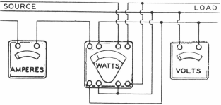
Voltmeter, Ammeter, Wattmeter Method
On reasonably steady loads simultaneous reading of volts, amperes and kilowatts can be made from indicating or recording meters, connected for 3- phase circuits as shown above. If the voltage is known, and is steady, a volt¬meter may not be necessary.
Power Factor = Kilowatts x 1000/1.73 x Volts x Amperes
Two Single-Phase Watthour Meters Method
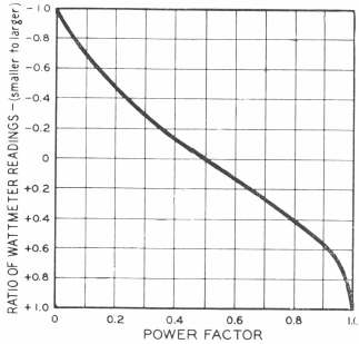
In some plants, power consumption on 3-phase circuits is measured by two single-phase watthour meters. The reading of these meters can be utilized to measure the average power factor over a short or long period of time, as desired. To obtain power factor over a short period of time, the number of revolutions of the meter disks are read simultaneously over the given period of time. The ratio of the two readings (that is, the smaller reading divided by the larger) determines the power factor according to the curve above. If one of the disks runs backwards, a minus ratio is obtained, and the power factor is below 0.5.
Three-Phase Wattmeter Method
If the load is reasonably steady, the power factor may be obtained fairly accurately by using a three-phase indicating or recording wattmeter. The meter is connected up in the proper manner for measuring 3-phase kilo¬watts. Then the potential lead in one phase is disconnected and a reading taken. This lead is reconnected and the potential lead in the other phase is disconnected and the second reading taken. In this way two single-phase readings are obtained, the same as in the previous method, and the curve will show the power factor.
Watthour Meter, Split-Core Ammeter Method
This method is probably the most readily available of any, for the only requirement, in addition to the power company’s watthour meter, is a split- core ammeter. It also has a very real advantage that it is not necessary to disturb any connections. Procedure is as follows:
(a) Determine Kilowatts
Avge. kw demand = D x M x N x 3600/Seconds x 1000
In the above D = kwh per revolution of the meter disk, as given by the meter manufacturer.
M = meter constant as determined by the ratios of the instrument transformers (usually marked on the meter by the power company).
N = number of turns of the disk in any chosen time.
Seconds = number of seconds in the time chosen for counting the disk revolutions.
(b) Determine Amperes
At the same time the disk revolutions are counted, the amperes in one conductor should be read by means of a split- core ammeter. (It is assumed the 3- phase load is fairly well balanced.)
Then, knowing the voltage,
Kva = 1.73 x Volts x Amperes/1000
And, Power Factor = Kilowatts/Kva
Watthour Meter, Reactive KVA- Hour Meter Method
A common method of metering power is by means of two 3-phase integrating watthour meters. One meter is connected in the regular way to measure kwh consumption. The other meter, as shown in the diagram below, has a “phase-shifting transformer” in the potential circuit so that the meter registers reactive-kva-hours.
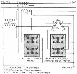
The ratio of the reading of kva meter to that of the kwh meter, over a given period, used with the table on page 15, gives the average power factor for that period.
Power Factor of Typical A-C Loads
UNITY (or near Unity) POWER FACTOR
Incandescent Lamps and Resistor Heaters operate at UNITY POWER FACTOR
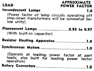
Resistance-type loads do not require a magnetizing-current component, hence operate at unity power factor. Synchronous motors are a so built to operate at unity power factor. Fluorescent lamps with capacitors usually have nearly unity power factor.
LAGGING POWER FACTOR
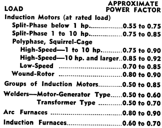
Induction Motors operate at LAGGING POWER FACTOR
Induction motors because they must be magnetized from the a-c line, and because they generally constitute a large part of the plant load, are the most prevalent cause of low power factor. Power factor of motor varies with size, speed and load.
LEADING POWER FACTOR
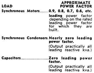
Synchronous Motors operate at LEADING POWER FACTOR
Leading power factor Synchronous Motors provide a magnetizing-current component to the a-c system that is utilized to supply requirements of induction motors. Capacitors and Synchronous Condensers also operate at leading power factor.
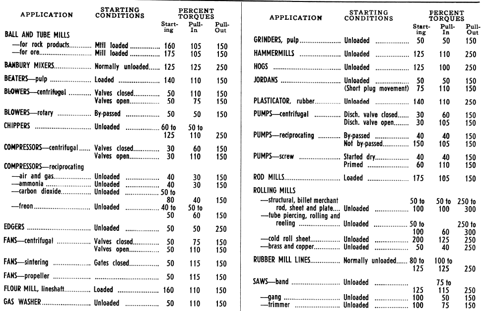
Approximate Torque Requirements of Synchronous Motor Applications
(In Percent of Full-Load Torque of the Motor)
Assumed Average Weight 40 pounds per cubic foot. American Society of Testing Standards.
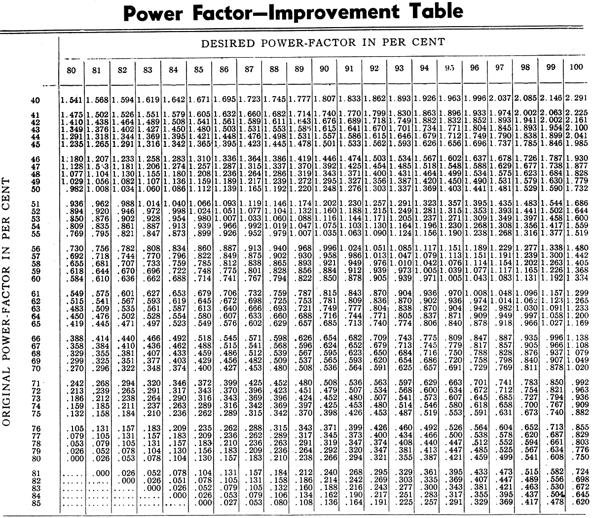
The size of capacitor necessary to raise the power-factor of a given load to a higher value can be found as follows:
Assume a 500-kva load at 60 per cent power-factor: 500 kva x .60 = 300 kw.
It is desired to raise the power-factor to 90 per cent. The capacitor kva necessary is found by multiplying 300 kw by the factor taken from the table, which is .85. The capacitor necessary would, therefore, be 255 kva.
Let us further assume that the next higher standard capacitor rating is selected (300 kva). What would be the resulting power-factor?
300/300 = 1.00
Referring to the table, we find that with an original power-factor of 60 per cent and a correction factor at 1.00, the ultimate power-factor would be practically 95 per cent.
Definitions of Electrical Terms
CYCLE—The period of a complete alternation of an alternating current circuit, comprising a positive and negative alternation.
FREQUENCY—Time required for an alternating current to pass through one complete cycle.
PHASE—The fraction of a cycle which has elapsed since a given electron last passed through its middle position in a positive direction.
POWER FACTOR—The power factor is the ratio of the true power to the apparent power of an alternating current system. The apparent watts are equal to the product of the volts and amperes, but owing to the possible “phase displacement” the power delivered, as measured by a wattmeter, may be actually less than the apparent power. The power factor may be expressed as a percentage but is usually written as a decimal fraction.
SINGLE PHASE—The term applying to an alternating current circuit energized by a single alternating e.m.f. Such a circuit is usually supplied through two wires.
POLYPHASE—A general term applied to an alternating system with more than one phase—see two phase and three phase.
TWO PHASE—The term applied to an alternating system comprising two electric circuits energized by alternating e.m.f.s which differ in phase by a quarter of a cycle—frequently referred to as quarter phase.
THREE PHASE—The term applied to an alternating system comprising three electric circuits energized by alternating e.m.f.s which differ in phase by one-third of a cycle.
Source: This article is a reproduction of an excerpt of “In the Public Domain” documents held in 911Metallurgy Corp’s private library.
