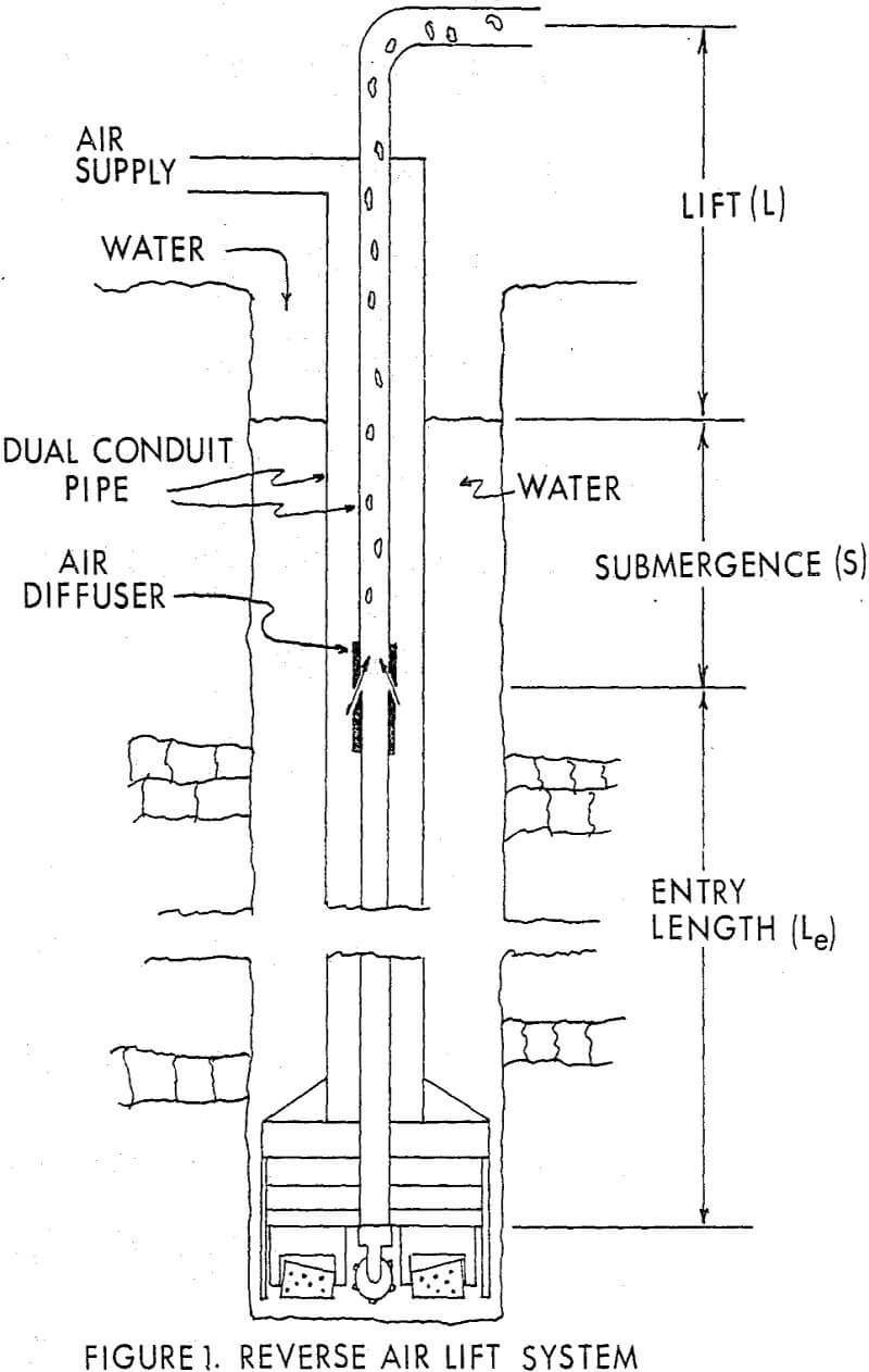
Numerous large scale drilling projects have made use of reverse circulation air lift methods. Reverse air lift pumping can be established by injecting gas into a column of liquid; the subsequently decreased density of the gas-liquid mixture allows atmospheric pressure outside the lift conduit to establish flow. The rate of flow can be controlled by varying the gas to liquid ratio.
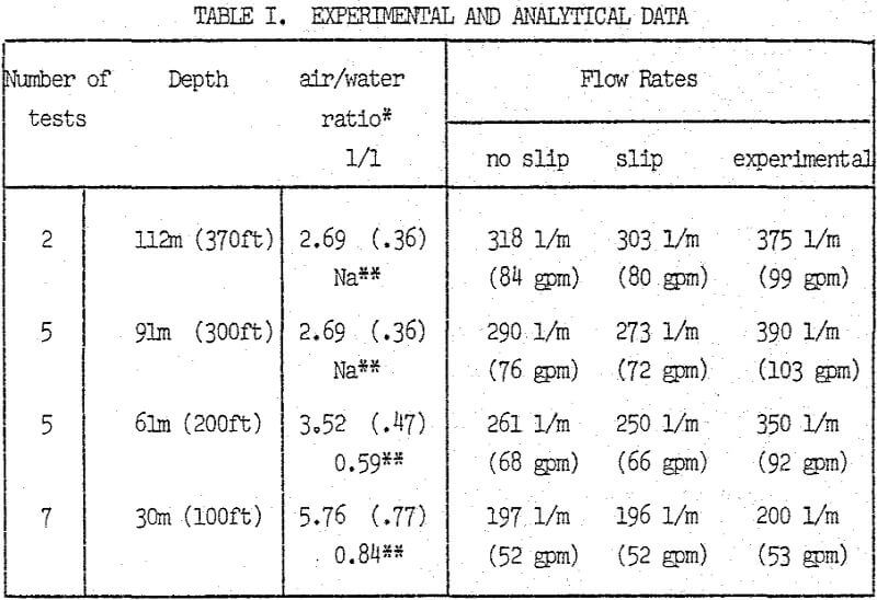
The first model assumed no slippage between air bubbles and water; results compared more closely with field data than with predicted values. When operating multiple diffusers, increased air to water ratios were required; however, the water flow rate increased also.

Based on the first assumption, the volumetric fraction of gas to liquid may be expressed as follows:

Returned pipe from the field show no significant signs of erosion. Thus, it may be assumed that in the prevailing flow regime, the friction occurs in a sub-boundary layer, not containing gas. Since the friction factor f is a function of Reynolds number and thus constantly changing, each integration step includes finding a new value of f. This is accomplished by Wegstein’s method of solution of non-linear equations. Input parameters include the physical dimensions of the system, flow rates, and air/water ratios which are then determined through interactive terminal operation.
Due to the design of the air-water separator, considerable amounts of water escaped the separator at high flow rates. The amount of water spilled by the separator was estimated and the upper flowrates thus are subject to errors larger than desirable.
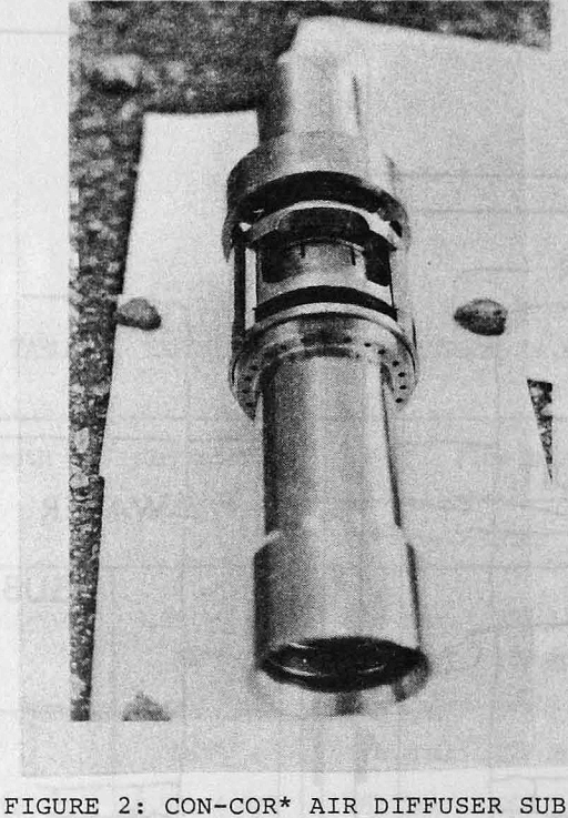
The diffuser design, forces air to be injected into the water at high velocities. If the pressure ratio for air to water at the injection sub is greater than 1.9, sonic (choked) flow will occur. Thus, the air bubbles introduced are small in size and impart through their high velocity momentum to the water column during mixing of the two phases. Extreme turbulence in the pipe may result in an invariant bubble size for a considerable distance above the injection point. Thus, it is likely that slug-froth flow cannot develop in the relatively short length of the lift system.


