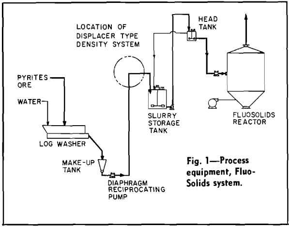
In the mineral industry measurement of density or specific gravity of slurries is often necessary or highly desirable. To date the most successful method of measuring the specific gravity of various media is to hand weigh a constant volume sample of the slurry. This method is time-consuming, however, and is intermittent rather than continuous. Most density measuring instruments in use today are variations of three basic systems: air bubble tube systems, radioactive methods, and displacer systems.
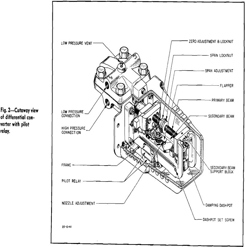
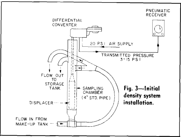
Type of Density Measuring System: This density measuring system consists of a detecting unit and a transmitting unit. It produces a transmitted pressure, with a range of 3 to 15 psi, that is proportional to the density of the slurry in the sampling chamber. An indicating, recording, or controlling instrument calibrated for the 3 to 15 psi range can be connected to the transmitter. More than one receiving instrument can be connected if desired.

The relationship between the apparent weight of the displacer and the specific gravity of the slurry is as follows:
A.W. = T.W. – 62.4(V) (S.G.)
where A.W. = apparent weight of displacer in pounds = T.W. — B.F., T.W. = true weight of displacer in pounds, B.F. = buoyant force of the slurry in pounds = 62.4 (V)(S.G.), V = volume of displacer in cubic feet, and S. G. = specific gravity of the slurry. Density of water under standard conditions of temperature and pressure = 62.4 lb per cu ft.
Since T.W. and V are constants for any given installation, the apparent weight must vary inversely with specific gravity.

By pin-connecting and suspending the displacer from the primary beam of the differential converter unit, a different pneumatic signal can be obtained for every change (or apparent change) in weight of the displacer. This pneumatic signal can then be transmitted to a Brown pneumatic receiver which continuously indicates and records these changes in units of specific gravity on a circular chart. 
Design Requirements of the Sampling Chamber: The sampling chamber is one of the most important parts of this density measuring system. Because of the type of slurry being measured and because of the location of the chamber in the process, the sampling chamber must meet the following design requirements:
- It must maintain a level of slurry in the chamber which will keep the displacer completely immersed at all times.
- It must provide a sample of slurry to be measured which will truly represent the slurry being pumped from the make-up tank to the storage tank.
- It must maintain a circulation of slurry through the chamber so that the density system can measure immediate changes in density of slurry from the make-up tank.
- It must not clog at the bottom of the chamber because of settling out of the solid material. (This has been the biggest stumbling block to all types of density measuring systems in the past.)
- It must eliminate the surges due to normal flow and, in this installation, to the pulsations of the reciprocating pump that pumps the slurry to the storage tank.

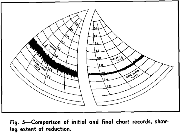
Results of Initial Field Tests of Density Measuring System: A density measuring system was assembled, incorporating the designs of the modified differential converter and sampling chamber as previously described.
Results of the initial tests were very gratifying but not completely successful. The primary problem that caused all previous attempts of continuously measuring slurry density to fail was solved. In more than two months of process operation, and for a period of about 5 hr each day when the ore slurry was being made and pumped to the main storage tank, the displacer remained completely immersed while the necessary circulation was maintained to prevent clogging at the bottom of the sampling chamber. Not a single instance of clogging occurred during this period of operation.

