Table of Contents
The pumping of abrasive and sometimes corrosive slurries is normally carried out at modest heads (say 100 ft) with specially designed centrifugal pumps. When heads become higher than this, two or more pumps are used in series but ultimately the system requires staged pumps with consequent increase of costs. The only other type of pump suitable for high heads is the Ram pump but this is notoriously subject to wear. The paper describes a novel application of the so-called “lock hopper” principle to continuous pumping of slurries. The pump itself is never in contact with the abrasive slurry nor is it subject to head or capacity limitation. It works by displacing slurry with the clear fluid component of the slurry (in most cases water) through cylindrical vessels fitted with plug valves to control the discharge and filling operations.
The principle of the “Lock Hopper” Pump
The displacement of a fluid by another fluid is not new. The most wellknown is the air pump, it having the advantage that the air after having completed its displacement of the fluid, can be vented to atmosphere, with no problem of disposal. Air, however, is highly compressible and the horsepower requirement for such a pump is considerably increased over that required for a liquid. Air compressors for very high pressures are also complex and expensive.
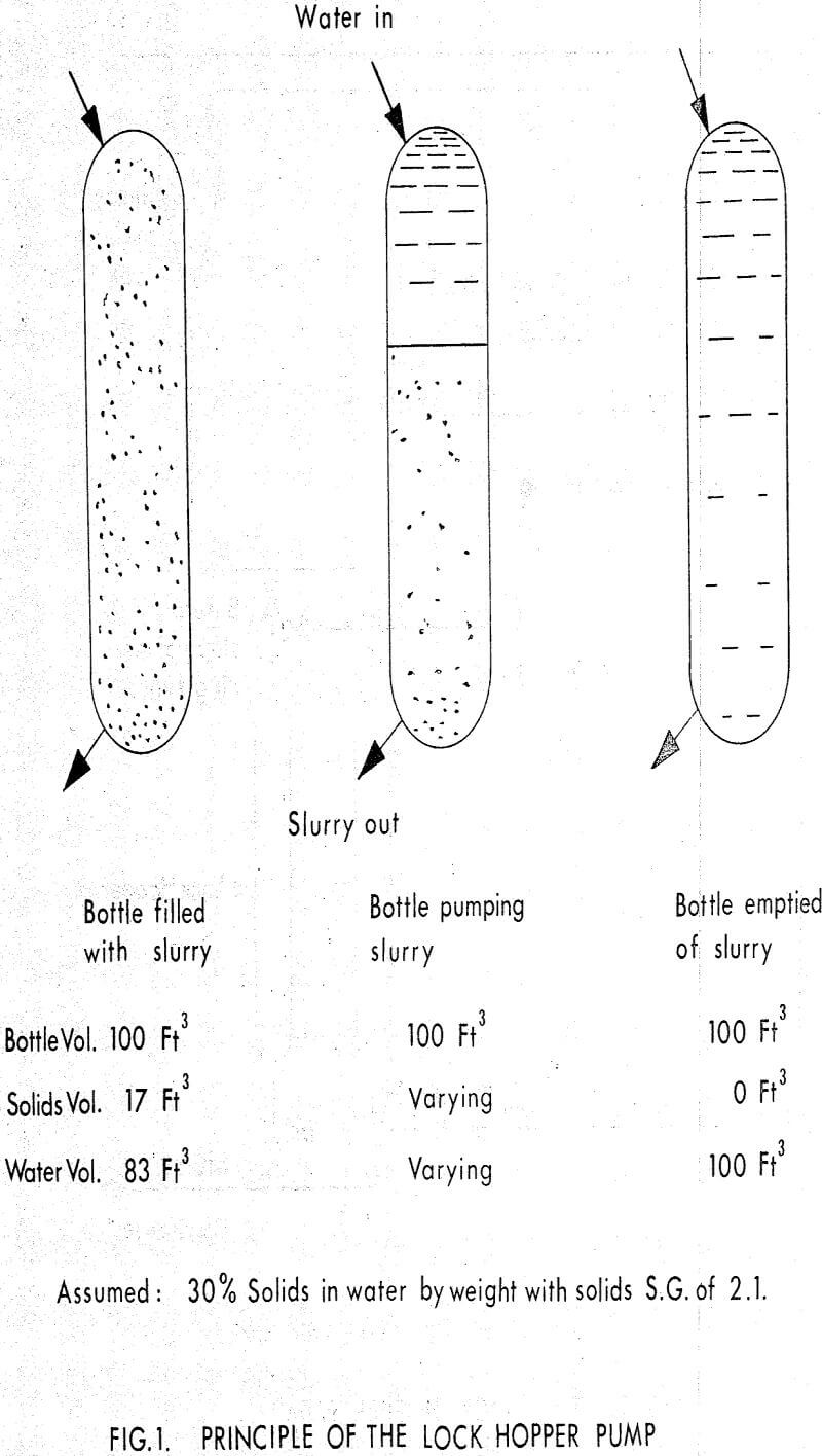
One turns therefore to consideration of a liquid pump. If a bottle is filled with a stable slurry and clear water admitted, it is possible to displace the slurry without admixture of the 2 liquids.
Suppose we mix water and solids (say s.g. 2.1) to 30% solids by weight and fill a bottle of 100 ft³ volume with this slurry. If water is admitted to the top of the bottle the slurry will be displaced until the bottle contains only water. If the slurry were piped to a lagoon we should have lost 83 ft³ of water. But, after pumping, the bottle contains 100 ft³ of slightly dirty water.
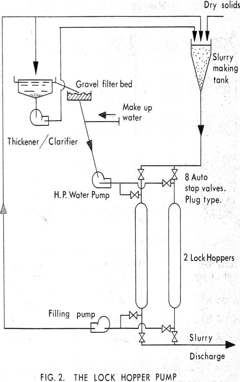
With only one bottle, the flow would be discontinuous and hence two bottles are required. The ingredients of a lock hopper scheme are therefore –
- 2 bottles + valves.
- high pressure water pumps
- pumping facilities for filling the slurry
- a water clarifier
- suitable controls
Technical problems inherent in the design
Having got this far, we asked ourselves what technical problems were introduced by such a design. The two problems considered most important were;
(a) the selection of suitable valves which would open and close repeatedly at intervals of the order of 1 minute and over months of continuous pumping, without undue wear and tear;
(b) Consideration of the lock hopper size and the possible admixture of slurry and water.
In considering the size of the lock hoppers, there is an interdependence with the valve problem, the criterion for non-mixing of the slurry and water and the cost of the pressure bottles. Model tests showed that an interface moving at speeds of around 1″ per second did not produce admixture.
Experience on the first Unit
The first unit was sold to Costain Mining Ltd. who are the agents for the Westfield Open-Cast site of the National Coal Board. Associated with this mining operation is a coal washery. Tailings proved a bigger problem than anticipated in the original design and a cheap method of pumping was required to replace the dumping of slurry by tankers. The concentration of solids in the thickener underflow could be as high as 53% by weight and we were asked to pump at this consistency through 3600 ft of pipeline and against a static lift of 80 ft.
The unit has been in operation for years, having paid off against lorry transport in under six months. Valve wear has been negligible but consumption of grease caused some dismay initially. The greasing installation consisted of a central lubricant pump running continuously in conjunction with a system of splitter blocks. Each valve in turn received its “shot” of lubricant. The grease used was rather expensive and in quantity, probably too much was used. The quantity was reduced and cheaper lubricants were tried by the client. Costs were still considered too high so the manufacturer fitted a. timing device reducing the greasing period to one quarter of the operating time. These alterations were considered satisfactory on a cost basis.
In the meantime, however, the manufacturer put on the market a plug valve lined with polytetrafluorethylene (P.T.F.E.) on the plug itself. The coefficient of friction is known to be extremely low and no lubricant is intended in its application. In the first place, one such valve was inserted in the system and behaved perfectly. At the time of writing nearly all the valves have been replaced, with good results.
In arriving at a suitable pipe size, slurry speed and concentration were varied within practical limits to optimise pipeline costs. It is clear from the investment costs, that the value of the pumps and ash handling, account for less than 5% of the total costs. A major change in pump cost is reflected in a minor change in overall costs.


