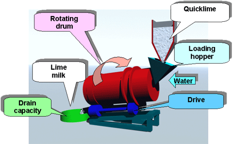
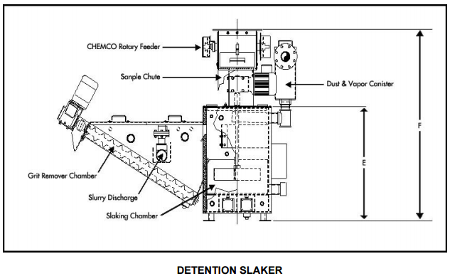
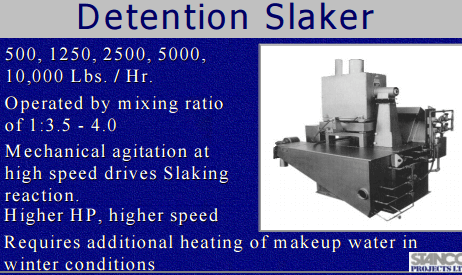
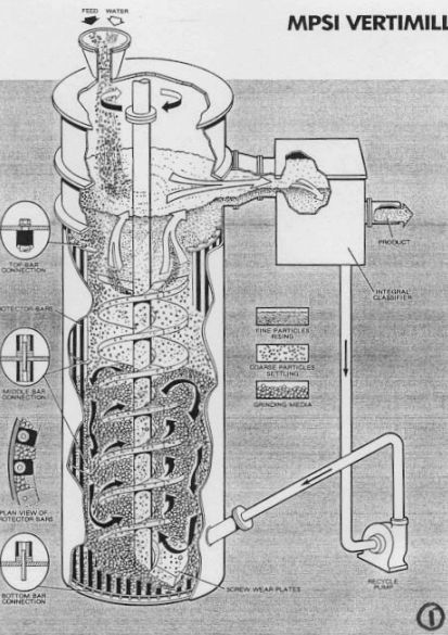
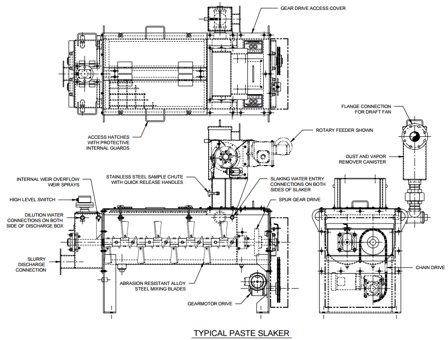
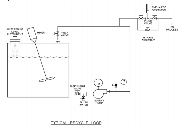
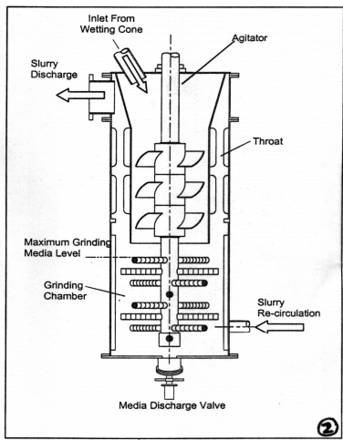
 A lime slaking and addition system can consists of two systems to control the pH in the rougher and cleaner flotation circuits. A pebble lime silo will dose dry lime to the SAG mill feed belt; a hydrated lime make down system will provide slurry lime to multiple addition points in the flotation circuit. Other lime delivery options are detention slakers and Verti-mill slakers. The proposed system is the lowest capital cost option available.
The operating costs are dependent on the slaker efficiency, hydrated lime consumption, proportion of pebble lime used, and slaker grit loss. Due to the increased reagent usage and cost of hydrated lime to achieve the same pH impact, the proposed lime addition system will have the highest operating costs of the three possible systems.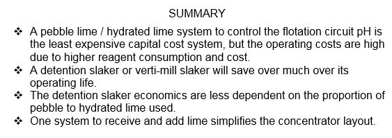
Initial flotation test work conducted included a box statistical study that compared grind size, reagent schemes, and pH. This test work indicates improved copper and molybdenum recovery and concentrate grade at a rougher pH of 10.8.
An earlier proposed lime addition system was changed from a verti-mill slaker to the currently proposed pebble lime / hydrated lime system. The revived cost estimate carried extra cost for a milk of lime tank and showed the verti-mill and 500 ton silo at zero cost. For a copper concentrator which will have one primary grinding line, so the primary pH control could be accomplished with pebble lime addition to the SAG mill feed belt. A smaller supplemental system would then be required for final pH control of the rougher and cleaner flotation circuits. 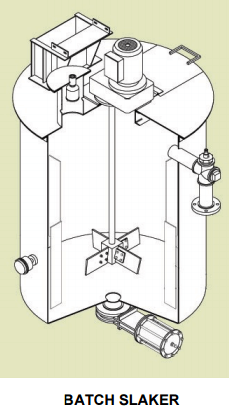 Test work has indicated that adding reagents to the grinding mill increases recovery. The pebble lime addition and hydrated lime systems were considered to be cleaner and easier to operate.
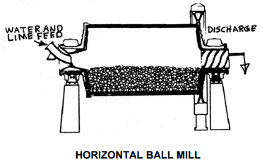
Calcium hydroxide particle size, and the resulting surface area, is dependent on the lime slaking temperature. The lime to water ratio and temperature in a SAG mill environment are not optimal to produce fine calcium hydroxide particles. Lime particles will continue to react under non-optimum conditions until a coating forms on the particle surface. There is no hard data on how much the lime consumption would increase compared to using slaked lime, but a chemist with on the project estimates lime consumption would increase 5 – 10%.
An economic comparison of the three lime addition systems was done. Budgetary quotations were obtained for a dual 2 ½ ton per hour (TPH) detention slaker and a 3 TPH Verti-mill slaker. Installation costs for each system was assumed to be 50% of the capital cost. Hydrated lime cost is estimated to be 20% more than pebble lime; no allowance for the additional trucking cost of hydrated lime was made. The pebble lime usage proportion of the pebble / hydrated system was assumed to be 90%, and a 10% lime consumption increase was applied to the pebble lime usage. For the detention slaker, the grit would be disposed of in the grinding circuit, and a 5% increase in lime consumption was applied. For the Verti-mill slaker, it was assumed that all the lime was converted to hydroxide. The results of the economic comparison for the first 10 years of mine life shown.

With the above assumptions, the economics of both the detention type and verti-mill slakers are positive, and the increased capital cost payback time is shorter.
If lime slaking efficiency is removed from the economic analysis, the higher cost and reagent consumption of hydrated lime still justifies the installation of a slaker. The proportion of pebble lime to hydrated lime was varied to find the breakeven point between the two slaker systems. For the detention slaker, the proportion was 94% pebble lime, and for the Verti-mill slaker, the proportion was 88%.
 |
 |
A single system for pH control will simplify the concentrator layout. With the proposed system, pebble lime is delivered to a storage silo above the SAG feed conveyor, and hydrated lime is delivered to the reagent building. With a slaker, the lime silo should
still be located close to the grinding area, since the SAG mill will be the major addition point, but it will not have to straddle the feed conveyor.
The pebble lime / hydrated lime system is not best when compared to a 500 ton silo and detention slaker system.
 |
 |
 |
 |
Types of Lime Slakers and lime slaking systems as well as Lime handling systems and https://budmash.com/en/index.php?id=28 were all helpful.
and https://www.chemcosystems.net/Files/Admin/Publications/An%20Overview%20of%20Lime%20Slaking.pdf
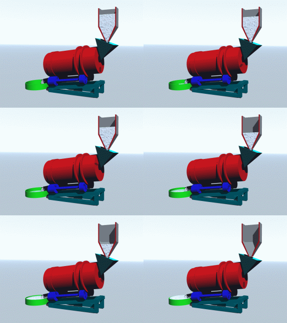
Bulk quicklime is used throughout the process. In addition plant solutions contain dissolved lime.
Lime is caustic and a skin irritant. Contact with the skin should be avoided, by wearing gloves and washing exposed areas.
Dusting should not normally be a significant factor. However should lime dust occur a mask should be worn.
Lime Manufacturing
Lime is the product that results from the calcination of limestone. Calcination takes place in rotary kilns or vertical kilns where the limestone is heated to approximately 2200°F. Limestone, mainly calcium carbonate (CaCO3), is transformed to lime, mainly calcium oxide (CaO). Carbon dioxide (CO2) is given off as a gas. The chemical formula is as follows:
CaCO3 + heat = CaO + CO2
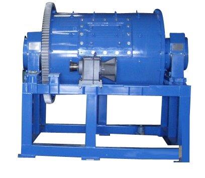
Limestone is obtained from open pit quarries or underground mines. Many lime plants are located adjacent to their limestone supply and are in fact mine-mouth operations. Some lime plants located on the Great Lakes receive their limestone from mines many hundred miles away located in northern Michigan. This limestone is transported in lake vessels that carry cargo weight up to 20,000 tons. I must point out that some lime plants produce lime from oyster and clam shells. This paper, however, concerns only that lime produced from limestone and shipped in dry bulk.
The limestone must be crushed and screened to a size suitable for feeding a kiln. Kiln feed limestone for a rotary kiln is normally sized approximately 2″ x 1/2″. The ratio of kiln feed limestone to lime produced is approximately 2 to 1. In other words, approximately two tons of limestone must be put into a kiln in order to produce one ton of lime. Kiln capacity, measured in tons per day, vary widely in the many lime plants located throughout the United States, but generally range from 200 tons per day to 1200 tons per day.
The limestone that does not go into the kiln particulary the fines (minus 3/8″) may be sold as an aggregate and used in asphalt production, subbase for construction sites, or in many other applications in site construction. Some plants pulverize or grind the limestone to a fine powder and sell it as rock dust. Rock dust is used to spray the internal surfaces of underground coal mines and seal in dangerous toxic gases. This powder limestone is also sold as aglime and sold as a supplement fertilizer in farming and lawns. Proper fertilization of fields requires that the soil be within certain ph levels. Aglime is used to adjust the ph level. Two other large markets for the non-kiln feed limestone are cement producing plants and acid neutralization in industrial plants. Limestone is also used in flue gas desulfurization.
Once the lime is produced, it is stored in silos normally constructed of steel or concrete. The capacity of these silos vary from a few hundred tons to more than 15,000 tons. Lime must, at all times, be protected from water or heavy moisture.
What is Lime used for
- Water Treatment Lime is used extensively in treating and purifying water for industrial and potable use. Although significant tonnage is shipped to this market of municipal and industrial water treatment plants, the end-users are widely spread geographically and individual shipments are relatively low tonnage. Lime, which is nonhazardous, can safely be shipped by truck or rail to these small end-users.
- Municipal and Industrial Waste Treatment Environmental agencies at all government levels, i. e., Federal State, County and Municipal, have been very active in the past few years in issuing more and stricter regulations controlling the treatment and disposal of sewage and industrial wastes. Lime usage in this market ranges from relatively simple processes of acid neutralization and sludge stabilization in mining areas to complex chemical treatment systems at municipal and industrial waste treatment plants.
- Steel Production in BOF’s (Basic Oxygen Furnaces) The tonnage of lime required in the BOF steel making process is so large and vital that many steel companies own their own lime plants. While these captive lime plants supply a large percentage of the steel companies requirements, commercial lime plants also supply high tonnage to steel plants.
- Flue Gas Desulfurization The Federal Clean Air Act of 1970 and subsequent changes and amendments require coal fired electrical power plants to remove given percentages or quantities of SO2 (sulfur dioxide) in the flue gases. Many power plants are successfully using lime in scrubber processes to comply with the many regulations controlling SO2 emmisions in flue gases.
Handling
Temperature of Lime is ≅ 2200’°F When Leaving Kiln: The temperature of lime when discharged from the kiln is ≅ 2200°F. Obviously, an effective cooling system must cool the lime sufficiently prior to transfer to silos by conveyor belts. A malfunction in the cooling system will result in burning of conveyor belts and I am certain that this misfortune has happened to more than one lime plant.
Calcined lime is discharged from the kilns across alloy grates in the bottom of the firing head to coolers. The coolers cool the lime by conterflow air quenching.
Ambient air, supplied by the cooler fan, passes through the bed of lime and absorbs the heat from the lime, and thus provides preheated secondary air to the kiln and for drying the coal prior to firing. The level of lime in the coolers is controlled to maintain given levels and thus given volumes of lime. Lime is discharged at the bottom of the coolers by means of a discharge plow mechanism and on to conveyor belts and transferred to storage silos. The temperature of the lime when discharged to the conveyor belts is approximately 250°F.
Hygroscopic Properties The hygroscopic properties of lime cause lime to readily absorb and retain moisture in the air. Precautions and protection systems against this moisture are a necessary part of any lime transfer and storage system. In spite of the built in protection against the elements of the weather, ambient air frequently has a high moisture content and this moisture reacts with exposed surface of the lime and causes air slaking of the surface of the lime, adding to the generation of more objectionable fine particles and dust.
This initial reaction of air moisture with the surface of lime is called air slaking or surface slaking. Essentially, lime (CaO) combines with water (H2O) and calcium hydroxide (Ca (OH)2) is produced.
CaO + H2O = Ca (OH)2 + Heat
The air slaking takes place mainly on the exposed surface of an undisturbed lime storage and usually no deeper than a few inches. The reaction does give some heat. The reaction will also reduce the flowability of the lime because of the fines generated. In transfer and storage systems that have relatively high rates of throughput, the air slaking has little effect of the lime handling system. Consideration must be given to the hygroscopic properties in slow through-put systems.
An interesting phenomena of lime related to air slaking is that the calcium hydroxide (Ca (OH)2) will in time react with carbon dioxide (CO2) in the ambient air and produce calcium carbonate – the product from which lime was produced.
Ca (OH)2 + CO2 = CaCO3 + H2O
When a pile of lime has been left in the open for several weeks, a crust will develop on the surface of the lime pile. This crust is mainly Calcium Carbonate.
Heat Given off When Lime is Exposed to Water
When lime is mixed with water heat is given off. This heat (an exothermic reaction) is an essential part of a slaking operation, where mechanical slakers are used in industrial processes to produce a lime slurry for scrubbing and other industrial uses. Transportation equipment however must be water tight and not allow rain or other water to contact the lime. Some unfortunate incidences when transportation equipment was not water tight are cited below:
- a. A dump truck loaded with lime was covered with a canvas tarpaulin, which had some holes in it. A light drizzle began and heat was given off as the water and lime combined to produce calcium hydroxide. The tarpaulin caught on fire. The truck caught on fire. The truck was destroyed.
- b. During a period of short lime supply, a company sent plywood-lined truck vans to be loaded with lime many hundred miles away. Provisionary load hatches were made by cutting holes in the top of the vans. After loading the holes were not closed and sealed so as to be watertight. The trucks were caught in rain storm. Some vans caught on fire. Several trucks were destroyed.
Size Disintergration During Distribution: From the moment lime comes out of a kiln until it is finally put to its end use, a large part of its life is spent in being transferred from one place to another. Each time lime is transferred some of the particles and pebbles break apart, become smaller, and hence the overall density becomes greater. Density must be known to certain prescribed accuracies if volumetric feeders are used to feed lime in an industrial process.
The following actual example of a distribution flow line where the density of lime has been known to change from approximately 55 pounds/ft³ to approximately 70 pounds/ft³, an increase of 40%.
- Lime with a density of approximately 55 pounds/ft³ is moved on a conveyor belt to the barge loading spout.
- When loaded into the barge the lime may fall 20 feet to 40 feet. The barge is then transported 200 to 300 miles.
- At the river terminal lime is transferred from the barge by a clamshell and dropped into a special landside hopper.
- Lime is fed from the hopper to a conveyor belt which transfers it to another conveyor belt and then drops it into a silo. If the silo is on the low side the lime may fall as much as 100 feet.
- Lime is loaded into dump trucks and transported up to 100 miles to a power plant.
- The lime is then dumped into an underground hopper and transferred to silos by a conveyor system that has up to five transfer points.
- The fall in the storage silos may be as much as 150 feet. A pneumatic system transfers the lime 300 feet from the silos to day bins above the slakers. This pneumatic line has no less than six 90° elbows (turns).
- From the day bins the lime is fed to slakers by screw conveyors. The density of the lime at this point is approximately 70 pounds/ft³ (compared to 55 pounds/ft³ when loaded into barges).
Variable Flowability Characteristics: The flowability of lime varies considerably. Generally, pebble lime, i. e., lime that is sized and screened to say 2″ x ½”, flows quite well. Powder, pulverized or very fine lime has very erractic flowability in very fine lime has very erractic flowability and in fact varies from almost not flowing at all to flowing to fast and flooding over transfer points. In storage this extremely fine lime may bridge over discharge points or form rat holes or craters. The angle of repose of this fine lime may well approach 90°, whereas pebble lime has angle of repose of 60°. On the other hand, once the lime breaks loose and drops a few feet, it is aerated, becomes fluidized, and literally flows like water. Vibrating feeders, air pads, stir chains, and live bottom silos are means of causing this lime to flow better. A little vibration is good. Vibration for too long a period or too strong can cause fine material to pack to concrete hardness. Means to minimize the effects of flooding include firm but flexible skirting on conveyor belts at transfer points, variable feed gates at the bottom of hoppers, surge boxes between the hopper and the conveyor belt, and product level controls in the hopper.
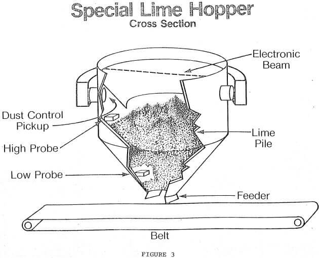
Clamshell-Hopper Unloading Problem: Many of the problems of lime handling discussed above were solved at a river terminal on the Ohio River. This terminal unloads barges by means of a crane with a clamshell, dropping the lime into a specially designed hopper for transfer to storage bins by conveyor belts and bucket elevators. Figure 3 shows this hopper. Some of the special features are described below.
- The vacuum air intake behind the bevels effectively controls dust in the hopper. However, if the level of the lime becomes too high, lime is sucked into the dust vacuum line. A high level probe was installed with an indicator light in the cab of the crane. The indicator light warns the crane operator that the lime level is high enough and must be allowed to descend. The crane operator cannot see into the hopper.
- If the clamshell is not sufficiently lowered into the hopper, then the dust control system is ineffective and lime dust is scattered in the surrounding area. An electronic beam was installed at the proper level in the hopper with an indicator light in the cab of the crane. The indicator light advises the crane operator that the clamshell has been sufficiently lowered into the hopper and can be safely opened.
- If the hopper becomes empty, then the next clamshell load of fine lime will fluidize and flood the conveyor belt. A low level probe was installed in the hopper. This probe turns off the feeder to the conveyor belt when lime descends below the lower level probe. The hopper is allowed to run empty only when barge unloading stops.
