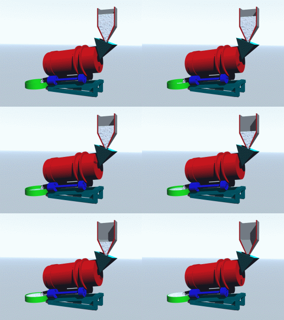
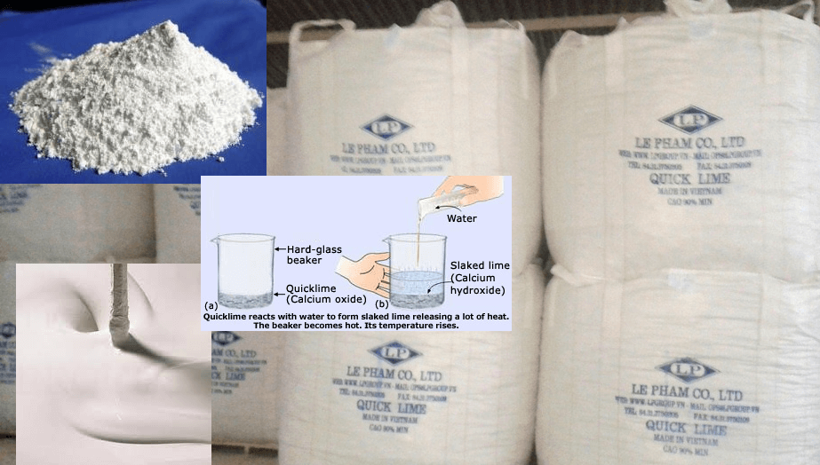
 The lime system is a packaged unit which operates automatically and continuously. The equipment provided in the package includes the lime silo, rotary feeder, lime slaker and lime slurry mix tank and agitator. The lime system is equipped with its own PLC which automatically provides lime slurry for the process.
Hydrated lime is stored in a 250 tonne lime storage silo. The silo is equipped with a dust collector and a bin live bottom activator. A high and low level alarm respectively will sound when extreme lime level conditions in the silo are experienced.
Lime is discharged from the lime silo by a variable speed rotary feeder into the lime slaker unit. Reclaim water is supplied to the lime slaker for the slaking process. Slaked lime is discharged from the slaker into the 2.5 meter diameter x 3.0 meter lime slurry mix tank, while the grit from the slaker is discharged into a grit box. The slaked lime in the mix tank is kept in suspension with a 3 hp agitator.
The mix tank is equipped with high and low level switches interlocked with the lime system PLC. The PLC will automatically slake lime according to the lime slurry level in the lime mix tank.
Slaked lime is pumped out of the lime slurry mix tank with one of two 10 HP 2-1/2″ x 2-1/2″ lime circulation pumps to the lime circulation loop in the plant.
Lime slurry is a difficult substance to deal with when piping it to feed points throughout the plant. It will quickly harden if allowed to stagnate, clogging pipes, and lining tanks with an ever-thickening layer of scale. The lime circulation loop is designed to deliver lime to feed points, maintaining constant flow, back to the lime slurry tank, in order to prevent clogging. Delivery at each feed point is accomplished by the use of pneumatically operated pinch valves, which are fully opened and closed on a pulsed basis to regulate lime flow. The danger of slow clogging in a throttled valve is thus relieved by the sudden bursts that a quickly opened valve will produce. The control is provided by a timer, which energizes a solenoid valve, which allows plant air to the diaphragm of the pinch valve when energized, and allows the air to vent when de-energized. The lime timer setting is changeable, and has been calibrated for each feed point so that the lime flow rate, from the length of time that the pinch valve is open versus the length of time the pinch valve is closed, averages out to the design flow rate.
As explained in the various sections of the manual, the addition of lime is solely for the purpose of maintaining pH.
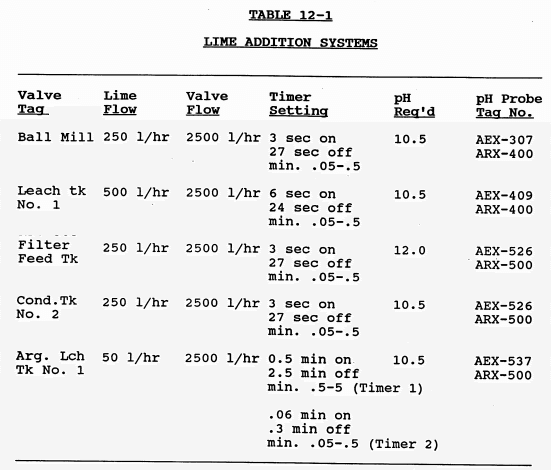
Lime is added by the use of the timer at five points in the plant. The four pH probes throughout the plant are located after each lime addition (two addition points are monitored by one pH probe), therefore the pH recorders can be monitored and the appropriate timer reset should the pH value not meet design criteria.
Note that for some of the sampler systems, two timers were required to achieve the required cycle times. The first timer opens a ‘window’ for the second to work within. One tag number identifies both timers, as they are interconnected.
Table 12-1 lists the valve tag number and location, the design flowrate, the valve fully open flow rate, the timer settings, the required pH, and the pH probe tag number associated with it. The timers are located on the mill control panel, and their settings are field adjustable should it become necessary. A sample calculation is shown after Table 12-1, and illustrates how to determine a timer setting for a given lime flow rate.  Lime Addition Sample Calculation:
Ball Mill Lime Timer
lime design flow rate / valve open flow rate = fraction of time open
250 1/hr / 2500 1/hr = 0.1
A 30 second cycle time was pre-selected, i.e., in 30 seconds, the valve must open and close once. Therefore, 0.1 x 30 seconds = 3 seconds open time, leaving 27 seconds for the closed time. Three seconds is long enough for sufficient flow, and the 30 second cycle time short enough not to cause a swinging effect in the pH level.
https://www.911metallurgist.com/flocculant-mixing-strength
https://www.911metallurgist.com/effect-operating-variables-metallurgical-process-parameters
