The stability of a liner system is influenced by many factors which can be compiled into four basic groups. They are:
- the liner system components and physical characteristics;
- the geometry and slope of the liner system;
- the loading conditions on the liner system; and
- the foundation conditions under the liner system.
Failures in the liner system that are due to one or more factors from the first three groups usually result in movement relative to the plans of the liner system. Failures associated with factors in the fourth group result in deformation(s) across the liner system section beyond its design limits. For purposes of these discussions a failure in the liner system refers to displacements or movements resulting in physical damage to the liner system such that it can no longer function.
Case History No. 1
The leach pad was constructed as a composite liner system consisting of 60-mil high density polyethylene (HDPE) placed over a compacted clay liner.
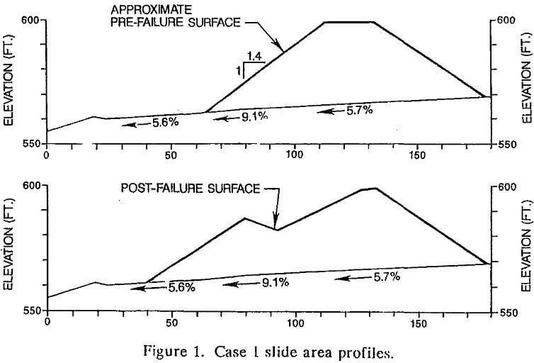
A slide occurred, consisting of downslope movement of a small wedge of ore from the base of the initial 40-ft high lift of ore stacked on the outer edge of the pad. The toe of the stacked ore was uphill from a support berm around the pad perimeter.
The grading of the pad in this area was steep (approximately eight percent average) due to foundation conditions. The clay subbase was relatively wet (above optimum moisture content for compaction) due to placing it in the rainy season.
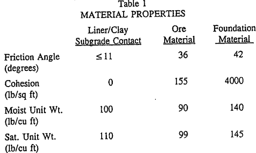
Two sets of analyses were conducted for the slide and heap stability. The first set was a “back analysis” to estimate the strength parameters required for the slide to occur under site conditions. The second set was to check remedial measures to stabilize the heap for future operations.
The computer program “STABL” developed at Purdue University was used to compute the analyses. A subroutine called “BLOCK2” was used to calculate the factors of safety (FOS). This was done to represent the observed mode of heap failure and to be consistent with the original design analyses. The heap geometry used in these analyses is based on field survey data and the as-built topography for the pad.
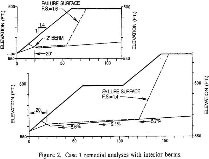
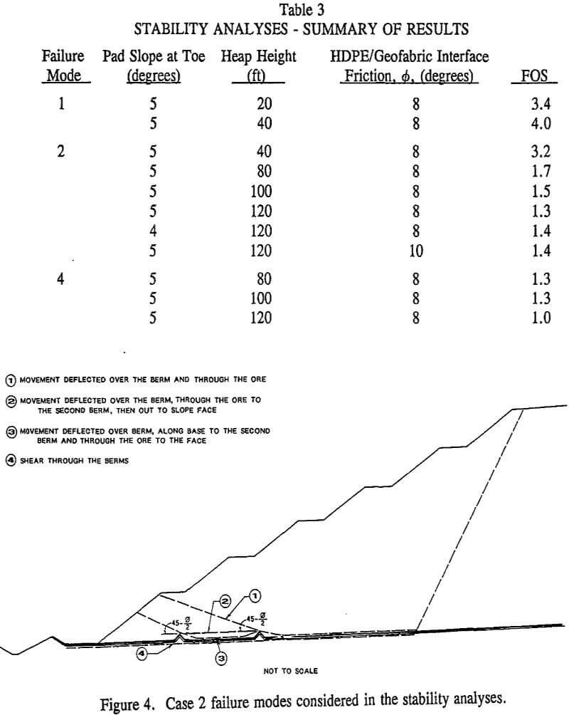
Additional stability analyses were conducted to assess the future heap stability. The results of these analyses indicated that the heap was stable, provided an additional berm was incorporated under the toe of the heap. The resulting passive resistance created by ore movement over the berm was sufficient to resist movement and stabilize the heap. Shearing through the base of the existing toe berm and the additional berm under the heap was also considered in the analyses. The results indicated that the shearing through the berm was not likely to occur as the calculated FOS was greater than 1.5. The modes of failure considered in the analyses are shown in Figure 2.
Case History No. 2
The plane of failure was along a geosynthetic material and VLDPE liner interface. The failure was induced by the ore stacking procedures over a cell dividing berm within the pad area.
The length of tear in the liner extended approximately 200 ft along the berm. The low friction angle between these two materials raised concern about the overall stability of the heap.
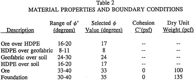
It was estimated that as the ore was being stacked over and parallel to the berm, the edge of the stacked ore extended far enough over the berm that the berm was located at the back of the “critical” active wedge of the exposed ore slope. The side slope of the berm acted as a steepened section of the critical surface. The berm slopes (2H:1V) exceeded the friction angle between the VLDPE and fabric (estimated at 8° to 10°). The pad slope out from the berm was less than 2%.
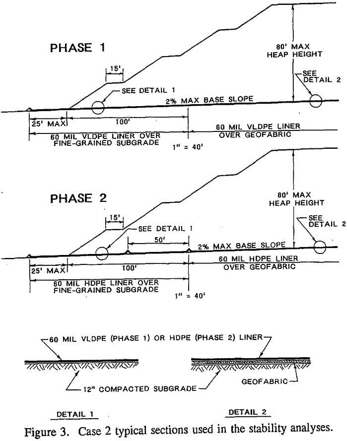
Analyses using a friction angle of 8° for the liner/geofabric contact showed the FOS against sliding for the heap to be near 1.1. Therefore, design revisions were required to increase the FOS against sliding. Several alternatives were considered including the use of textured liner, and revising the pad grade. The least expensive alternative was to include a series of shear berms in the foundation similar to CASE 1 remedial measures. This alternative also did not require a permit revision which may have been the case had materials change in the approved liner section or the system redesigned to exclude the geofabric. The two berms one along the edge of the geofabric and one about 50 ft from the toe of the heap were included as “shear keys” to compensate for the reduced friction between the liner and geofabric. Typical sections of the original and revised liner systems are shown in Figure 3.
